Embed Size (px)
Citation preview

m2
IS 1367 (Part 2) :20021s04759-1:2000
( ?%!7?7ymf)?m)
Indian Standard
TECHNICAL SUPPLY CONDITIONS FORTHREADED STEEL FASTENERS
PART 2 TOLERANCES FOR FASTENERS — BOLTS, SCREWS,STUDS AND NUTS — PRODUCT GRADES A, B AND C
(Third Revision )
ICS 21.060.10
@ BIS 2002
BUREAU OF INDIAN STANDARDSMANAK BHAVAN, 9 BAHADUR SHAH ZAFAR MARG
NEW DELHI 110002
.-
December 2002 Price Group 14
‘\.J

Bolts, Nuts and Fasteners Accessories Sectional Committee, BP 33
NATIONAL FOREWORD
This Indian Standard (Part 2) (Third Revision) which is identical with ISO 4759-1:2000 ‘Tolerancesfor fasteners—Part 1:Bolts, screws, studs and nuts — Product grades A, B and C’ issued by theInternational Organization for Standardization (ISO) was adopted by the Bureau of Indian Standardson the recomrhendation of the Bolts, Nuts and Fasteners Accessories Sectional Committee and approvalof the Basic and Production Engineering Division Council.
This standard was originally published in 1961 and subsequently revised in 1967 and 1979. The lastrevision was based on ISO 4759/1-1978. This revision of the standard has been taken up to align itwith ISO 4759-1:2000 by adoption under dual numbering system.
The text of ISO Standard has been approved as suitable for publication as Indian Standard withoutdeviations. Certain terminology and conventions are, however, not identical to those used in IndianStandards. Attention is drawn especially to the following:
a) Wherever the words ‘International Standard’ appear referring to this standard, they shouldbe read as ‘Indian Standard’.
b) Comma (,) has been used as a decimal marker while in Indian Standards, the current practiceis to use a point (.) as the decimal marker.
In this adopted standard, reference appears to certain International Standards for which Indian Standardsalso exist. The corresponding Indian Standards which are to be substituted in their place are listedbelow along with their degree of equivalence for the editions indicated:
International Standard Corresponding Indian Standard
ISO 225:1983 IS 8536:1987 Fasteners—Bolts, screws, studs andnuts—Symbols and designation of dimensions (firstrevision)
ISO 286-1:1988 IS 919(Part 1):1993 ISO systems of limits and fits:Part 1 Basis of tolerances, deviations and fits (secondrevision)
ISO 286-2:1988 IS 919(Part 2):1993 ISO systems of limits and fits:Part 2 Tables of standard tolerance grades and limitdeviations for holes and shafts (second revision)
ISO 885:2000 IS 4172:1987 Dimensions for radii under the head ofbolts and screws (first revision)
ISO 965-3:1998 IS 14962(Part 3):2001 ISO General purpose metricscrew threads —Tolerances : Part 3 Deviations forconstructional screw threads
IS 8000( Partl ):1985 Geometrical tolerancing ontechnical drawings: Part 1 Tolerances for formorientation, location and run-out and appropriategeometrical definitions (first revision)
1s0 1101:2000
Degree ofEquivalence
Identical
do
do
Identically
do
Identicalz)
—
.
.
“1
(Continued on third coved
1) ~dentic~l ~i~ ISO 885:1978.‘4 ldenti~~l ~~ ISO 1101 :1983

Contents
IS 1367 (Part 2) :20021s0 4759-1 :2000
Page
1 Scope ................................................................................................................................................... ........... 1
2 Normative references ....................................................................................................................................2
3 Tolerances for metric bolts, screws and studs ..........................................................................................3
4 Tolerances for metric nuts ..........................................................................................................................25
5 Tolerances for tapping screws ...................................................................................................................36
Annex A (informative) Tolerances ...........................................................................................................................44
Annex B (informative) Examples of dimensioned and tolerance fasteners ......................................................46
Annex C (informative) Examples of gauges and other measuring devices ....................................... .................49

IS 1367 (Part 2) :20021s0 4759-1 :2000
Indian Standard
TECHNICAL SUPPLY CONDITIONS FORTHREADED STEEL FASTENERS
PART 2 TOLERANCES FOR FASTENERS — BOLTS, SCREWS,
STUDS AND NUTS — PRODUCT GRADES A, B AND C
( Third Revision)
1 Scope
This part of ISO 4759 specifies a selection of tolerances for bolts, screws, studs and nuts with ISO metric threadsand with product grades A, B and C and for tapping screws with product grade A.
NOTE The product grades refer to the size of the tolerances where grade A is the most precise and grade C is the leastprecise.
The tolerances, except tolerances for threads, are selected from the system of limits and fits specified in ISO 286-1and ISO 286-2. The tolerances for metric threads are taken from the series of tolerance classes specified inISO 965-3. The tolerances for tapping screw threads are covered in ISO 1478.
The tolerances of form and position are specified and indicated in accordance with ISO 1101, ISO 8015 andISO 2692.
The tolerances specified in this part of ISO 4759 apply to fasteners prior to coating unless otherwise specified. Seealso ISO 4042.
Deviations from the tolerances specified in this part of ISO 4759 are only permitted in product standards wherethere are valid technical reasons. In cases where there is a difference between the tolerance requirements in thispart of ISO 4759 and the product standard, the product standard takes precedence.
It is recommended that these tolerances also be used for non-standard fasteners.
Dimensions and tolerances given in this part of ISO 4759 are in millimetres.

IS 1367 (Part 2) :2002
1s0 4759-1 :2000
2 Normative references
-.
The following normative documents contain provisions which, through reference in this text, constitute provisions ofthis part of ISO 4759. For dated references, subsequent amendments to, or revisions of, any of these publicationsdo not apply. However, parties to agreements based on this part of ISO 4759 are encouraged to investigate thepossibility of applying the most recent editions of the normative documents indicated below. For undatedreferences, the latest edition of the normative document referred to applies. Members of ISO and IEC maintainregisters of currently valid International Standards.
ISO 225:1983, Fasteners — Bolts, screws, studs and nuts — Symbols and designation of dimensions.
ISO 286-1:1988, /S0 system of limits and fits — Part 1: Bases of tolerances, deviations and fits.
ISO 286-2:1988, /S0 system of limits and fits — Part 2: Tables of standard tolerance grades and limit deviations forholes and shafts.
ISO 885:2000, General purpose bolts and screws — Metric series — Radii under the head.
ISO 965-3:1998, ISO general purpose metric screw threads — Tolerances — Part 3: Deviations for constructionalscrew threads.
ISO 1101:2000, Geometrical Product Specifications (GPS) — Geometrical tolerancing — Tolerances of form,orientation, location and run-out.
ISO 1478:1999, Tapping screws thread.
ISO 1479:1983, Hexagon head tapping screws.
ISO 2692:1988, Technical dra wings — Geometrical tolerancing — Maximum material principle.
ISO 4032:1999, Hexagon nuts, style 1 — Product grades A and B.
ISO 4042:1999, Fasteners — Electroplated coatings.
ISO 4757:1983, Cross recesses for screws.
ISO 7053:1992, Hexagon washer head tapping screws.
ISO 7721:1983, Countersunk head screws — Head configuration and gauging.
ISO 8015:1985, Technical drawings — Fundamental tolerancing principle.
ISO 10509:1992, Hexagon flange head tapping screws.
ISO 10642:1997, Hexagon socket countersunk head screws.
ISO 10664:1999, Hexalobular internal driving feature for bolts and screws.
\
2

IS 1367 (Part 2) :2002
1s0 4759-1 :2000
3 Tolerances for metric bolts, screws and studs
3.1 Dimensional tolerances
Symbols and designations of dimensions are specified in ISO 225.
Tolerance for product gradesFeature Notes
A B c
.1.1 Tolerance level
;hank and bearing surface close close wide
)ther features close wide wide
1.1.2 External thread 6g 6g 8g For certain
(but 6g forproducts and
propertycoatings, othertolerance classes
class 8.8for threads may
and hi9W be specified in th(relevant productand coatingstandards.
1,1.3 Driving features
s Tolerance s Tolerance1.1.3.1 External
<30 h13 < 18 h14
1.1.3.1.1 Width across flats >30 h14 >18 <60 h15
Q
>60< 180 h16
I>180 h17
—— ———
s
Figure 1
B
-4-
S
Figure 2
3

IS 1367 (Part 2) :20021s0 4759-1 :2000
.—
Tolerance for product gradesFeature Notes
A B c
3.1.3.1.2 Width across corners
a
e~in = 1,13 S~i”
emin= 1,12 ~minfor bolts and screws with flange
-t-—— w and other cold forged heads without trimming
operation
Figure 3
Q
t?~in= 1,3 $~i”
“+-
t
Figure 4
3.1.3.1.3 Height of head
R= @ F ‘s’4 ‘s’5 “ ‘“’F
Figure 5
\,\

IS 1367 (Part 2) :2002
1s0 4759-1 :2000
5

IS 1367 (Part 2) :20021s0 4759-1 :2000
——
6

IS 1367 (Part 2) :2002
1s0 4759-1 :2000
FeatureTolerance for product grades
A BNotes
c3.1.3.2.3 Depth of hexagon sockets The depth of hexagon — — For the time bein!and slots sockets and slots is generally
specified in product applicablew w
%%
standards only as a tolerances cannoi
t tminimum. It is be specified.restricted by theminimum wallthickness W.
:+,
~4j) –— —
–1
w
13ii
t
;$
Figure 11
3.1.3.2.4 Cross recesses See ISO 4757 for all dimensions except pen-etration depths. For penetration depths seeappropriate product standard.
3.1.3.2.5 Hexalobular recesses See ISO 10664 for all dimensions except pen-etration depths. For penetration depths seeappropriate product standard.
3.1.4 Other features
3.1.4.1 Head diameter
‘II@ ‘! “3a - - ‘;’;’;::ds
Figure 12
D
Combined controlof diameter and
x;– height for counter-
\ sunk head screwsin accordancewith ISO 7721 or
‘& RI
ISO 10642.
:3,m“
3’ –h14 — .
Figure 13
7
IS 1367 (Part 2) :2002
1s0 4759-1 :2000
Tolerance for product gradesFeature Notes
A B c
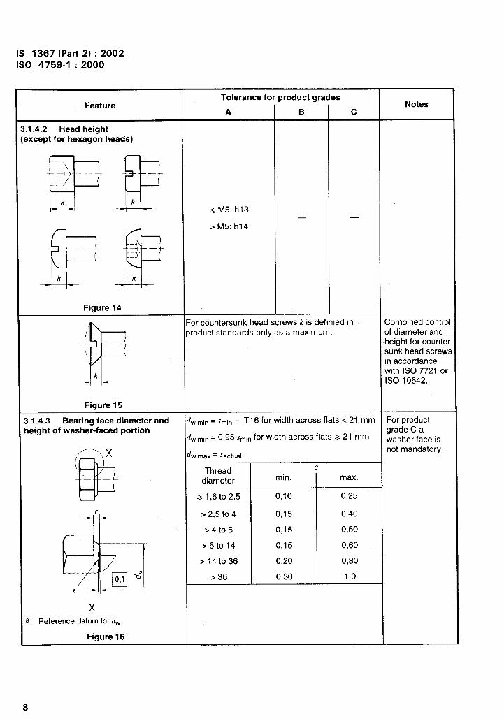
.1.4.2 Head height?xcept for hexagon heads)
y+ p GM5:h,3
F& ‘M5:h14 - -
Figure 14
P
For countersunk head screws k is definied in Combined controlproduct standards only as a maximum. of diameter and
:– height for counter-
\ sunk head screwsin accordance
kwith ISO 7721 orISO 10642.
Figure 15
1.1.4.3 Bearing face diameter and d~ ~i” = S~in – IT16 for width across flats <21 mm For product
leight of washer-faced portiond~ ~in = 0,95 Sminfor width across flats >21 mm
grade C awasher face is
@
x dnot mandatory.
w max = sactual
Threadc
diameter min. max.
>1,6 to 2,5 0,10 0,25
c
*’
>2,5 to 4 0,15 0,40
>4t06 0,15 0,50
>6to14 0,15 0,60
>14t036 0,20 0,80
n0,1 ~’ >36 0,30 1,0
a
xa Reference datum for dw
Figure 16
8

IS 1367 (Part 2) :2002
1s0 4759-1 :2000
-. Tolerance for product grades . . .t-eawre Notes
A B c
x
@
— ——
El0,1
e
dw is defined in product standards only as a
minimum.
a m3
xReference datum for dw
Figure 17
Threadx
dw For product grade
m y7 -
diameter A only
=/, > < min.b’ —1+——
-4/–2 m>
2,5 dkmin–0,14
a
El
2,5 5 dk min – 0,250,1
5 10 dk ~in – 0,4
x 10 16 dk ~in – 0,5
16 24 dk ~in – 0,8Reference datum for dW
24 36 dk ~in – 1Figure 18
36 — dk ~in – 1,2
D
da for undercut
products, see the
-cm da for products without undercut is specifiedappropriateproduct standard.
in ISO 885.
Figure 19
9

IS 1367 (Part 2) :20021s0 4759-1 :2000
Feature
3.1.4.4 Length
[
=3=1Figure 20
Tolerance fo
A
js15
woduct grades
B
js17
c
[< 150js17
l>150ilT17
Notes
10
\‘,.
‘(
-,..

IS 1367 (Part 2) :20021s0 4759-1 :2000
FeatureTolerance for product grades
A BNotes
c
1.1.4.5 Thread length P is the pitch ofthread.
Bolt 1~is the minimum
length of the un-threaded (plain)shank,
~ .2P ~ +2P ~ .2P /g is the maximumo 0 0 length of the un-
threadecf shank(thread run-out in-cluded) and istherefore the
Tie rod minimumclamping length.
R ‘;’P ‘;’ b: ;Z:
are not specified
Stud in the productstandard.
M ::, :7 ::, ‘m;;Tt&ta’
Figure 21
3.1.4,6 Shank diameter
r“ -
The tolerance is
— — .— not applicable in
L
h13 h14 *IT15 the areas of theunderhead filletand threadrun-out.
—— –&. _— _— _
;g=;
Reduced shank diameter = pitch diameter
~
Figure 22
11
IS 1367 (Part 2) :2002
1s0 4759-1 :2000
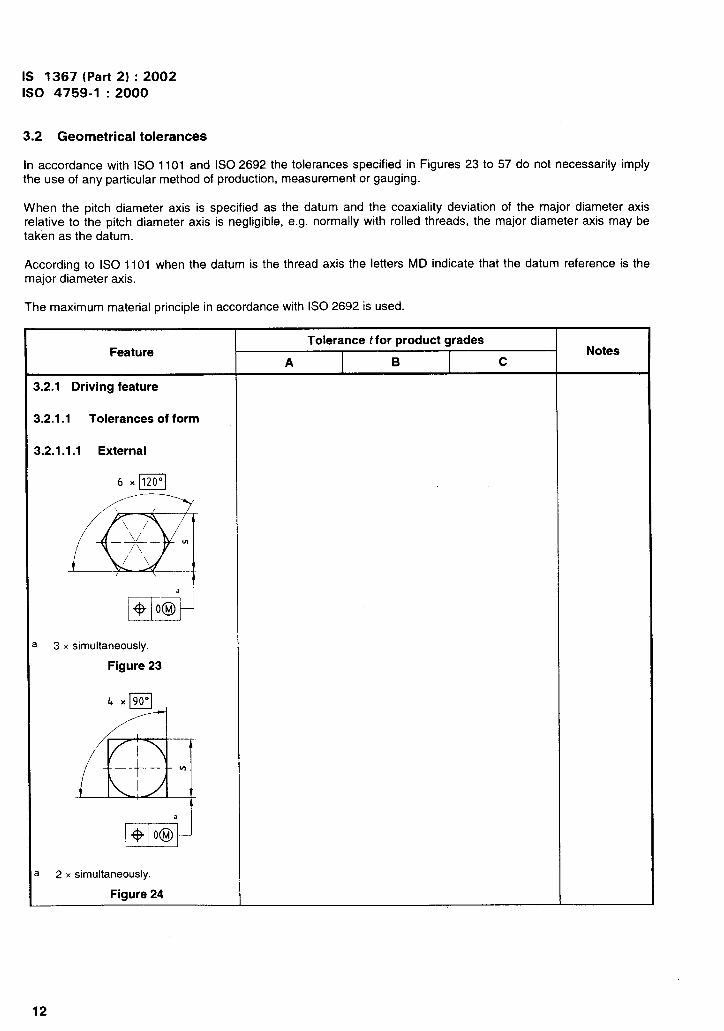
3.2 Geometrical tolerances
In accordance with ISO 1101 and ISO 2692 the tolerances specified in Figures 23 to 57 do not necessarily implythe use of any particular method of production, measurement or gauging.
When the pitch diameter axis is specified as the datum and the coaxiality deviation of the major diameter axisrelative to the pitch diameter axis is negligible, e.g. normally with rolled threads, the major diameter axis may betaken as the datum.
According to ISO 1101 when the datum is the thread axis the letters MD indicate that the datum reference is themajor diameter axis.
The maximum material principle in accordance with ISO 2692 is used.
Tolerance t for product gradesFeature Notes
A B c
1.2.1 Driving feature
).2.1 .1 Tolerances of form
1.2.1 .1.1 External
6xB
q
\
~\/~ - ~
//i/
a
Ho OM
3 x simultaneously.
Figure 23
4 xpFJ
43
-4-- “
+ o@a
1 2 x simultaneously.
Figure 24I
12

Feature
).2.1 .1.2 Internal
Cl6 X 120”
~ 3 x simultaneously.
Figure 25
).2.1.2 Tolerances of position
rktldA@l
1 nA MDb
k+ c16 X 120”
Tolerance t for product grades
A B c
2 lT13 2 IT14
I
2 IT15
.-
1S 1367 (Part 2) :2002
1s0 4759-1 :2000
Tolerance ,based on
dimensions
s
Notes
F——
d
0,5d max.
0,5d max.
The datum A shall be as close to the head as possible but within 0,5d distance of the head and shall be either wholly
plain or wholly threaded but shall not include the thread run-out or underhead fillet.
MD means that tolerance applies in relation to the axis of the cylinder derived from the major thread diameter.
3 x simultaneously,
Figure 26
rEmm
,b, c See Figure 26.
Figure 27
b6 X 120°
2 IT13 2 IT14 — s
13

.—
..
IS 1367 (Part 2) :20021s0 4759-1 :2000
Tolerance t for product gradesFeature
c
b, C See Figure 26
Figure 28
I c1A MDbI Aw—
--l
t-
W -o-——–-l
da
,b, c See Figure 26.
Figure 29
),b, C See Figure 26.
FVaure 30
I
c16 X 120°
cl6 X 120”
@
\/‘\— —
/\
6 Xm
A
2 {Tl 3
2 IT13
2IT13
B
—
—
—
c
—
—
—
‘olerance tbased onimensions
d
d
d
Notes
‘1
14

IS 1367 (Part 2) :2002
1s0 4759-1 :2000
Feature
I ~A MDb
L---‘, c See Figure 26.
Figure 31
t- -i
, b See Figure 26
Figure 32
I PA MDb
.f+12Pl-=-
, b See Figure 26.
Figure 33
14DwYA MDb
/:”— m–——
\c da
, b See Figure 26.
Figure 34
Tolerance t for product grades
A
2 IT12
2 IT12
2 IT12
2 IT12
B
—
2 IT13
2 IT13
2 IT13
c
2 IT14
2 IT14
2 IT14
Tolerancebased on
dimension
d
d
d
d
Notes
15

IS 1367 (Part 2) :2002
1s0 4759-1 :2000 ~
Feature
See Figure 26.
Figure 35
Tolerance t for product grades
A
2 IT12
2 IT13
B
—
—
c
—
—
Tolerance tbased on
~imensions
d
d
Notes
! b See Figure 26.
For referee purposes coaxiality of cross recess shall be assessed by means of a penetration gauge point in accordance
with ISO 4757.
Figure 36
uA MDb
I, b See Figure 26.
See Figure 36.
Figure 37
2 IT13 — — d
16

IS 1367 (Part 2) :2002
Feature
3.2.2 Other features
3.2.2.1 Tolerances of positionmd run-out
~,b See Figure 26.
Figure 38
I
~,b See Figure 26.
9A MDb
E??
m–——
da
Figure 39
EDa31?A PDC
IJ
ud m-
1
Tolerance t for product grades
A
2 IT13
2 IT13
2 IT13
B
2 IT14
2 IT14
2 IT14
c
2 IT15
.
2 IT15
1s0 4759-1 :2000
Tolerancebased on
dimension:
dk
dc
d
Notes
PD means that the tolerance applies in relation to the axis derived from the pitch diameter.
Figure 40
“1
\
17

IS 1367 (Part 2) :2002
1s0 4759-1 :2000
Feature
m.A.————b – —
d =“
See Figure 40,
Figure 41
m
~1A PO(
eMd
See Figure 40.
Figure 42
w~A PDC
%d
See Figure 40.
Figure 43
Tolerance t for product grades
A
lT13d
21T13e
IT13
IT13
B
—
—
—
c
—
—
—
Tolerance tbased on
dimensions
d
d
d
Notes
~ Fo~setscrews.
For all other
products,
‘,%

IS 1367 (Part 2) :20021s0 4759-1 :2000
See Figure 40.
The gauge datum feature A shall be as close to the respective part of the shank as possible but shall avoid the thread
run-out.
Figure 45
iT13 IT14 — d
See Figure 40.
The gauge datum features A and B shall be as close to the respective part of the shank as possible but shall avoid the
thread run-out.
Figure 46 I
“1
19

IS 1367 (Part 2) :2002
1s0 4759-1 :2000
Tolerance tfor product grades Tolerance tFeature based on
ANotes
B c dimensions
1.2.2.2 Tolerances)f straightness
F
— @t@d :s
o Q
MDb <8 t = 0,0021 + 0,05 0- 0
++
T=!!!!!
>8 t = 0,00251 + 0,05~ln
.—. ON00
b ——
0- 0-— —— :CJ
II N.—. — * II
..
1~;VI ~-Q-Q
See Figure 26.
Figure 47
= “
,&
-Gg o-=- o● +
.—. — <8 t = 0,0021+ 0,05 ‘R 30’34.— m ——–-—— 00
>8 t= 0,00251 + 0,05 0- 0-
~g—.— .—.
,, N
III w:
w :x=
See Figure 26.
Figure 48
1= :8 f = 0,002/ + 0,05MDb
>8 t= 0,00251+ 0,05
I!&s!3
.—. — .—. — . —
—m — ———— b –-
—.—. — .—. — .—.
i
) See Figure 26.
Figure 49
‘“,

IS 1367 (Part 2) :2002
Iso 4759-1 :2000
21
.\\

IS 1367 (Part 2) :2002
1s0 4759-1 :2000
Tolerance t for product grades Tolerance t
FeatureA B
+Z/qtli]
uA MDb
A.
EEppb’ — -c——
da
b See Figure 26.
Up to 0,8 dk diameter only.
Figure 53
c
++
b See Figure 26.
Line of highest points on any radial line.
Figure 54
0,08
r0,15
0,17
I 0,21
I 0,25
l==0,29
0,34
0,38
0,42
E
0,46
0,50
0,57
E0,63
0,69
0,76
0,82
I 0,44
I 0,47
I 0,50
I 0,55
131
3,5
0,3 4
5
6
7
0,34 8
0,42 10 . See Figures 51
0,50 12 and 52
0,58 14
0,68 16 In case of flangebolts, tolerances
0,76 18 apply to type F
0,84 20 and type U.
1,00 I 24 I
1,26 I 30 I
1,38 I 33 I
a1,52 36
1,64 39
0,88 42
0,94 45
1 48 ,
1,1 52
22
..i.
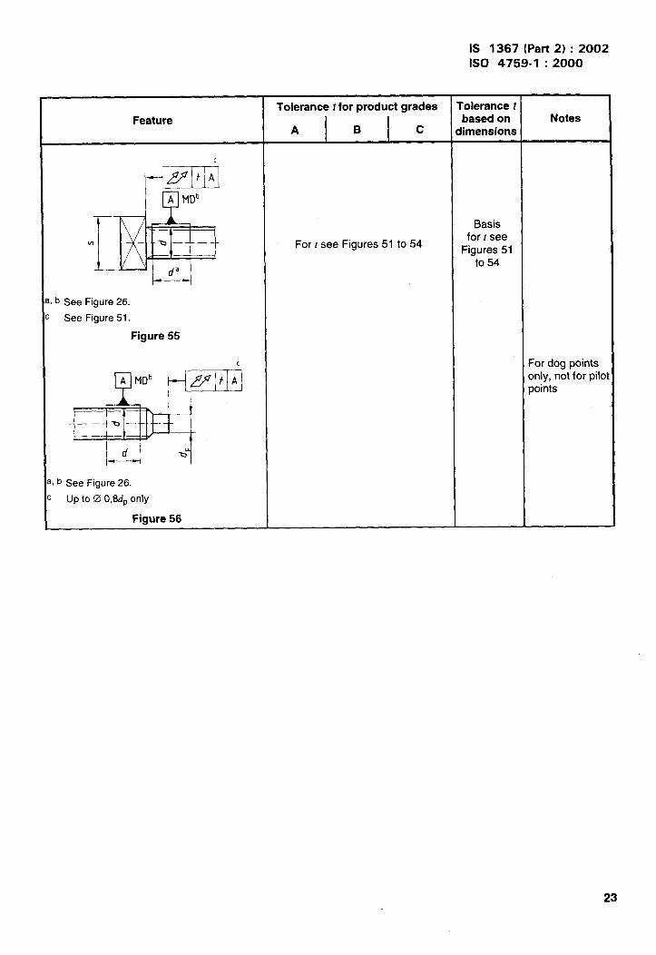
Feature
c
Fflt A
uA MDb
b See Figure 26.
See Figure 51.
Figure 55
, b See Figure 26.
Upto00,8dP only
Figure 56
Tolerance t for product grades
A B c
For r see Figures 51 to 54
IS 1367 (Part 2) :2002
1s0 4759-1 :2000
rolerance tbased onDimensions
Basisfor r see
Figures 51to 54
Notes
For dog pointsonly, not for pilopoints
23

IS 1367 (Part 2) :2002
1s0 4759-1 :2000
Feature
3.2.2.4 Permissible deviation‘rem the form of bearing face
&x
-b ———
xradial lines between da max and & min.
I According to product standard.
Figure 57
0,005 d
Tolerance t for product grades
A B c
Tolerance tbased on
flimensions
d
Notes

IS 1367 (Part 2) :2002
1s0 4759-1 :2000
4 Tolerances for metric nuts
4.1 Dimensional tolerances
NOTE Symbols and designations of dimensions are specified in ISO 225.
25

IS 1367 (Part 2) :2002
1s0 4759-1 :2000
Tolerance for product gradesFeature Notes
A B c
1.1.3 Driving features
I.1 .3.1 Width across flats
Q
o
J_ Toler-
‘/s
antes Tolerance
< 30 h13 < 18 h14s >30 h14 >18 <60 h15
>60 <180 h16Figure 59 >180 h17
Q.
o+-
See figure 59 See figure 59
s
Figure 60
1.1.3.2 Width across corners
@
+.
Figure 61
D
o+
e~ln = 1,3 .S~int
Figure 62
e~ifl = 1,13 ~~ifl
‘1

IS 1367 (Part 2) :2002
1s0 4759-1 :2000
~
Tolerance for product gradesFeature Notes
A B c
1.1.4 Other features
L1 .4.1 Height of nuts
REBd<12mm:h14
For slotted nuts
8
12mmcd<18mm:h15 h17 and castle nutssee 4.1.5.1
d>18mm:h16
m
Figure 63
‘revailing torque type nuts (with non-_netallic insert)
I!!I!lh
Prevailing torque type all metal hexagon Tolerance of h, see productnuts standards
E
T
h
Figure 64
27
..i.

IS 1367 (Part 2) :2002
1s0 4759-1 :2000
~lwamin= (), fj ,nmi”
28
\\

IS 1367 (Part 2) :2002
1s0 4759-1 :2000
Feature
4.1.4.3 Bearing face diameterand height of washer-faced portion
EDm3
Bx
—
Reference datum for dw
Figure 67
f;-’x
Figure 68
Tolerance for product grades
A B c
~Wmin= ~min- IT16for width across flats <21 mm1’w Min = 0,95 ~minfor width across flats >21 mm
iw max = ‘actual
Thread c
diametermin. max.
a 1,6 to 2,5 0,10 0,25>2,5 to 4 0,15 0,40
>4t06 0,15 0,50>6to14 0,15 0,60
>14t036 0,2 0,8>36 0,3 1,0
{Wmin for hexagon nuts with flange in accordancevith product standards
Notes
Requirementsapply to both
sides ofsymmetrical
parts.
i
29

IS 1367 (Part 2) :20021s0 4759-1 :2000
Tolerance for product gradesFeature Notes
.A B c
m
d<5m_m:damM=l,15d Requirementsapply to both
lx 5mm<d<8 mm: sides of—.
mmsymmetrical
da ~ax = d + 0,75 parts.
d >8 mm: damaX = l,08d
for all sizes: da ~in = d
m
lx
.B“
@
(x
—mm
= 90° to 120°
Figure 69
L1.5 Special products
L1 .5.1 Castle nuts, slotted nuts
w
A
d. h14 h15 h16
m h14 h15 h17
mW n H14 H14 H15
m w h14 h15 h17
w m ~ see row-values for hexagon nuts style 1
9
(see ISO 4032)
c——
mW
m
Figure 70

IS 1367 (Part 2) :2002
1s0 4759-1 :2000
4.2 Geometrical tolerances
In accordance with ISO 1101 and ISO 2692 the tolerances specified in Figures 71 to 83 do not necessarily implythe use of any particular method of production, measurement or gauging.
Where the nut thread is used as the datum the pitch diameter shall be the reference diameter.
The maximum material principle in accordance with ISO 2692 is used.
Tolerance t for product gradesFeature Notes
A B c
.2.1 Driving features
,.2.1.1 Tolerances of form
+ + I 00’1
I
I 3 x simultaneously.
Figure 71
+\ Ooj
~ 2 x simultaneously.
Flgtwe 72
31

IS 1367 (Part 2) :20021s0 4759-1 :2000
Feature
2.1.2 Tolerances of position
a6 K 120”
3 x simultaneously.
Figure 73
p!EE31Ei!d
56 X 120”
3 x simultaneously.
Figure 74
I —
k’@IA -sJ -1-
rl& x 90”
2 x simultaneously.
Figure 75
Tolerance tfor product grades
A
2 IT13
2 IT13
2 IT13
B
2 IT14
2 IT14
2 IT14
c
2 IT15
—
2 IT15
‘olerance tbased onimensions
s
s
s
Notes
32

IS 1367 (Part 2) :2002
1s0 4759-1 :2000
Tolerance r for product grades Tolerance tFeature
Abased on
BNotes
c dimensions
4.2.2 Other features
4.2.2.1 Tolerances of position
E
~I$t~A~
A
2 IT14 2 IT15 — dc
m“ m
———
Figure 76
3x
@
~t~A~
A
2 IT13 2 IT14 2 IT15 d
c m
Figure 77
F
~f3t~A~
B
A
2 [T13 2 IT14 — dk——
b’—=
Figure 78
‘1
33

IS 1367 (Part 2) :20021s0 4759-1 :2000
Tolerance r for product grades Tolerance r
Featurebased on
A Bdimension Notes
cd
L2.2.2 Tolerance of total run-out 1,6 For0,04
2symmetricalparts the
& ~~
&Aa 2,5 perpendicularityA — requirement
30,08
shall apply for
3,5 both faces.
m w4———
0,15 0,3 5
6
~ Up to 0,8s diameter only. 7
Figure 79 0,17 0,34 8
0,21 0,42 10
w
flt Aa0,25 0,50 12
A 0,29 0,58 14
. — 0,34 0,68 16
m W 0,38 0,76 18— —
0,42 0,84 20
0,46 0,92 22
a Up to 0 0,8s only. 0,50 1 24
Figure 80 0,57 1,14 27
0,63 1,26 30
w
A&t Aa 0,69 1,38 33
0,76 1,52 36
0,82m
1,64 39—— b’——— 0,44 0,88 42
0,47 0,94 45
a Up tO 0 o,8dk Only. 0,50 1 48
Figure 81 0,55 1,1 52
34

IS 1367 (Part 2) :2002
1s0 4759-1 :2000
Tolerance r for product gradesFeature Notes
A B c
M
~Hz7q
A
> t.
!
For r see values for Figures 79, 80 and 81.
i Line of highest points on any radial line.
Figure 82
4.2.2.3 Permissible deviation from
the shape of bearing face
g’
x
-ci[
vb
d
.
~,/-+=+]
L---\————,,1 ‘T b>b“ ~
x3 Radial lines between da maxand cIWmin.
J According to product standard.
Figure 83
o,oo5Li’
\
IS 1367 (Part 2) :2002
1s0 4759-1 :2000
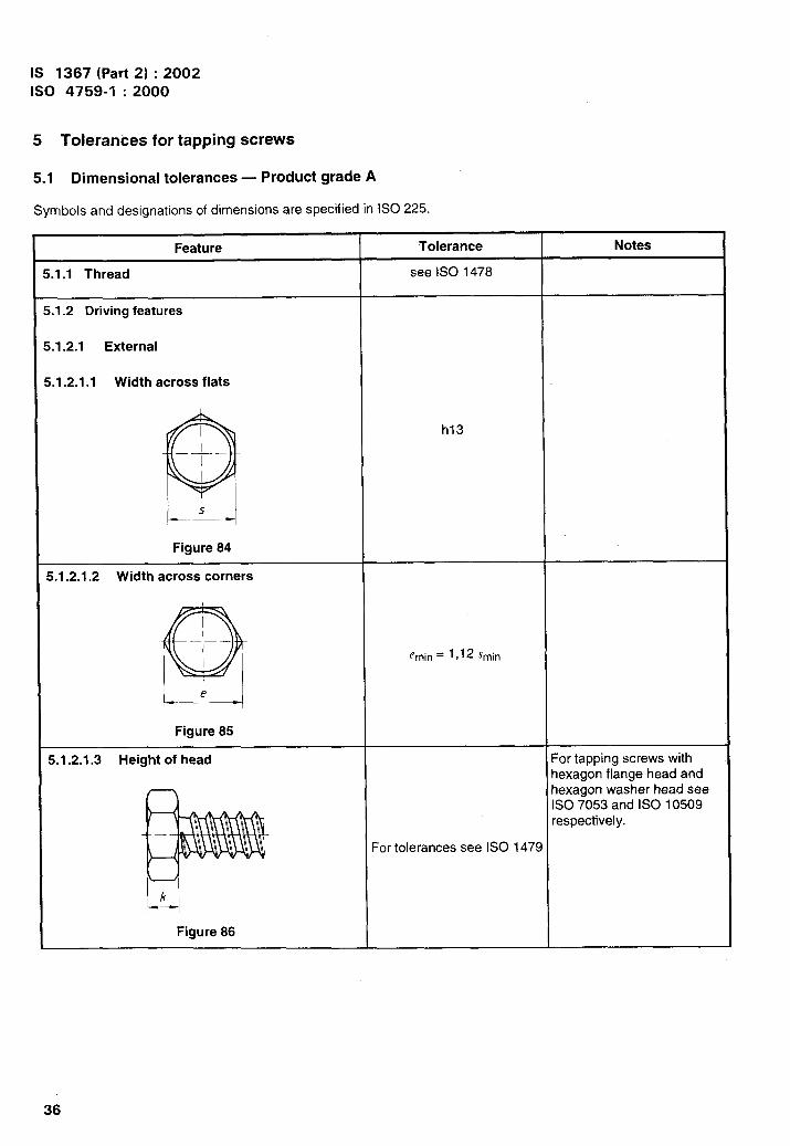
5 Tolerances for tapping screws
5.1 Dimensional tolerances — Product grade A
Symbols and designations of dimensions are specified in ISO 225.
Feat II re Tolerance Notes
h13
e~in = 1,12 .Y~in
36
\‘.
...

IS 1367 (Part 2) :2002
1s0 4759-1 :2000
37

IS 1367 (Part 2) :2002
1s0 4759-1 :2000
h14
38

IS 1367 (Part 2) :2002
1s0 4759-1 :2000
Feature
S.1.3.3 Length
t- ‘–”--”-”–- “---”--” “--”--”‘-”” ““””--”----
Type C
Type R
3Type F
Figure 93
Tolerance
Types C and R
1 I Tolerance
-s--Lu_Type F
I Tolerance
<19 0-0,8
>19 <38 0-1,3
>38 0
-1,5
Notes
IS 1367 (Part 2) :2002
1s0 4759-1 :2000
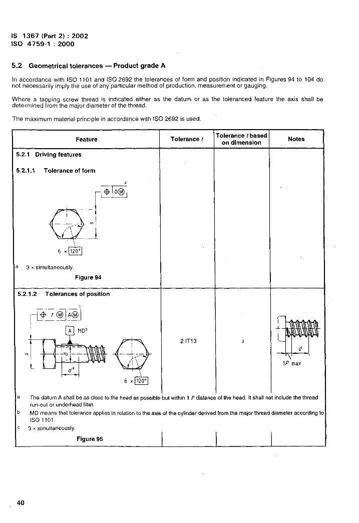
5.2 Geometrical tolerances — Product grade A
In accordance with ISO 1101 and ISO 2692 the tolerances of form and position indicated in Figures 94 to 104 donot necessarily imply the use of any particular method of production, measurerr,ent or gauging.
Where a tapping screw thread is indicated either as the datum or as the tolerance feature the axis shall bedetermined from the major diameter of the thread.
The maximum material principle in accordance with ISO 2692 is used.
The datum A shall be as close to the head as possible but within 1 P distance of the head. It shall not include the thread
run-out or underhead fillet.
MD means that tolerance applies in relation to the axis of the cylinder derived from the major thread diameter according t(
1s01101.
3 x simultaneously.
Figure 95
40

IS 1367 (Part 2) :2002
Feature
❑ Ml)’
c
l-=-l~,b See Figure 95.
Figure 96
c
1----
L.b See Figure 95.
Figure 97
. ..—._.v ——
&-Q1 nA MDb
u daL-1, b See Figure 95.
Figure 98
Tolerance f
2 IT12
2 IT12
2 IT12
1s0 4759-1 :2000
roierance t basecon dimension
d
d
d
Notes
I
41

IS 1367 (Part 2) :20021s0 4759-1 :2000
sb See Figure 95.
For referee purposes assessment of co-axiality of cross recess features shall be by means of a perpetration gauge point in
accordance with LSO 4757.
d
fik
I
1
I
I
6
I
I
‘.

Feature
5.2.2.2 Total run-out
I,b
I, b
ww
l-=-
See Figure 95,
Up to 0,8.r diameter only.
Figure 102
See Figure 95.
up to 0,8 dk diameter only.
Figure 103
5.2.2.3 Straightness
See Figure 95.
Figure 104
Tolerance t
d
ST2,2ST2,9ST3,5ST4,2ST4,8ST5,5ST6,3ST8
ST9,5
t
0,08
0,16
0,16
0,160,3
0,30,3
0,34
0,42
t = 0,003/+ 0,05
IS 1367 (Part 2) :20021s0 4759-1 :2000
rolerance t basecon dimension
d
d
.
Notes
Tolerance t:alculated as‘Ollows:
‘=l,2dxt_an2°
for / < 20d
43

IS 1367 (Part 2) :2002
1s0 4759-1 :2000
Annex A(informative)
Tolerances
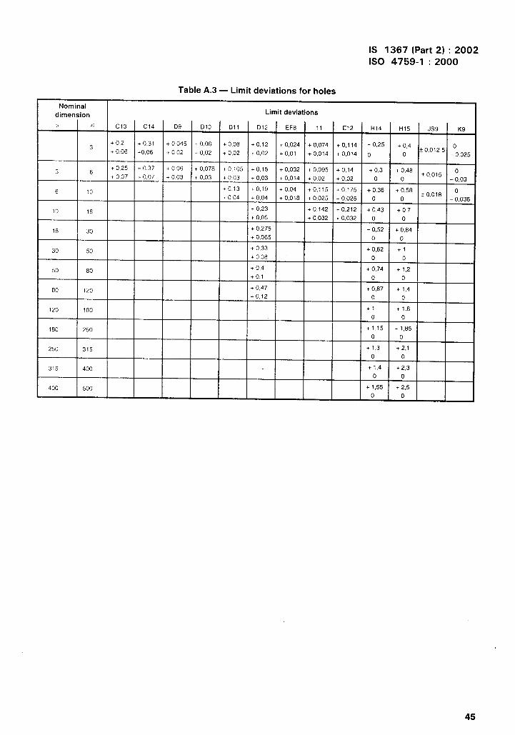
Numerical values of IT tolerance grades are given in Table A.1 and the limit deviations for shafts and for holes are
given in Tables A.2 and A.3 respectively. These tolerances are taken from ISO 286-1 and ISO 286-2.
Table A.1 — Numerical values of standard tolerance grades IT for basic sizes up to 500 mm
Nominal dimension Standard tolerance grades
> < IT12 I IT13 IT14 IT15 IT16 IT17
Tolerances
3 0,1 0,14 0,25 0,4 0,6 1
3 6 0,12 0,18 0,3 0,48 0,75 1,2
6 10 0,15 0,22 0,36 0,58 0,9 1,5
10 18 0,18 0,27 0,43 0,7 1,1 1,8
18 30 0,21 0,33 0,52 0,84 1,3 2,1
30 50 0,25 0,39 0,62 1 1,6 2,5
50 80 0,3 0,46 0,74 1,2 1,9 3
80 120 0,35 0,54 0,87 1,4 2,2 3,5
120 180 0,4 0,63 1 1,6 2,5 4
180 250 0,46 0,72 1,15 1,85 2,9 4,6
250 315 0,52 0,81 1,3 2,1 3,2 5,2
315 400 0,57 0,89 1,4 2,3 3,6 5,7
400 500 0,63 0,97 1,55 2,5 4 6,3
Table A.2 — Limit deviations for shafts
I Nominal dimension ! Limit deviations I
> < h13 h14 h15 h16 h17 js14 jsl 5 js16 js17
30 0 0 0 0
–0,14 – 0,25 -0,4 -0,6 -1t0,125 * 13,2 ~ 0,3 ? 0,5
3 60 0 0 0 0
to,15 f 0,24 f (),375–0,18 – 0,3 – 0,48 -0,75 -1,2
* 0,6
6 100 0 0 0 0
– 0,22 – 0,36 – 0,58 -0,9 -1,5~o,18 * 0,29 * 0,45 * (),75
10 180 0 0 0 0
-0,27 -0,43 -0,7 -1,1 -1,8* 0,215 * (),35 f 0,55 & 0,9
18 300 0 0 0 0 ~ o,26 k 0,42
-0,33 – 0,52 – 0,84 -1,3 -2,1t 0,65 f 1,05
30 500 0 0 0 0
-0,39i 0,31 f 0,5 k 0,8 ? 1,25
– 0,62 -1 -1,6 -2,5
50 800 0 0 0 0
-0,46 -0,74 -1,2 -1,9 – 3,0* (3;37 ~ o,6 t 0,95 fl,5
80 1200 0 0 0 0
-0,54 – 0,87 -1,4 -2,2 -3,5* 0,435 f 0,7 ~1,1 * 1,75
120 1800 0 0 0 0
-0,63 -1 -1,6 -2,5 -4* r3,5 f o,8 k 1,25 fz
180 2500 0 0 0 0
t 0,575 ~ o,925-0,72 -1,15 – 1,85 -2,9 -4,6
t 1,45 * 2,3
250 3150 0 0 0 0
– 0,81 -1,3 -2,1 -3,2 -5,2~ o,65 i 1,05 tl,6 ~ 2,6
315 4000 0 0 0 0
-0,89 -174 -2,3 -3,6 -5,7i 0,7 +1,15 *1,8 k 2,85
0 0400 500
0 0 0–097 –1!=+, -CIK ,4 –ccl * 0,775 * 1,25 *2 *3,15
44
\‘\\
IS 1367 (Part 2) :2002
1s0 4759-1 :2000
Table A.3 — Limit deviations for holes
Nominaldimension Limit deviations
> < C13 C14 D9 D1O Dll D12 EF8 11 E12 H14 H15 JS9 K9
+ 0,2 + 0,31 + 0,045 + 0,06 + 0,083
+0,12 + 0,024 + 0,074 +0,114 + 0,25 + 0,4 0+ 0.06 +0,06 10,02 + 0,02 io,olz 5+ 0,02 + 0,02 + 0,01 + 0,014 + 0,014 0 0 -0,025
3+ 0,25 + 0,37 + 0,06 + 0,078 +0,105 +0,15 + 0,032
6 + 0,095 +0,14 + 0,3 + 0,48 0+ 0,07 + 0,07 + 0,03 to,o15+ 0,03 + 0,03 + 0,03 + 0,014 + 0,02 + 0,02 0 0 -0,03
6 10+0,13 + 0,19 + 0,04 +0,115 +0,175 + 0,36 + 0,58
f0,018o
+ 0,04 + 0,04 + 0,018 + 0,025 + 0,025 0 0 -0,036
+ 0,2310 18 +0,142 +0,212 + 0,43 + 0,7
+ 0,05 + 0,032 + 0,032 0 0
18 30+ 0,275 + 0,52 + 0,84
+ 0,065 0 0
+ 0,3330 50 + 0,62 +1
+ 0,08 0 0
50 60+ 0,4 + 0,74 + 1,2
+0,1 o 0
80 120+ 0,47 + 0,87 +1,4+0,12 o 0
120 180 +1 +1,6
o 0
180 250 + 1,15 + 1,85
0 0
250 315 +1,3 +2,1
o 0
315 400 +1,4 + 2,3
0 0
400 500 + 1,55 + 2,5
0 0
‘1
45

IS 1367 (Part 2) :2002
1s0 4759-1 :2000
Annex B(informative)
Examples of dimensioned and tolerance fasteners
I
t-
Fig. 42
m
1
-G
F,&tc-Fig, 52
1-
a Up to 0,8 dk diameter only.
b 3 x simultaneously.
=ml
Fig, 25
bxm/ 4
@
/
-+-Q
s+p o@jb
Fig. 25
!iEimEIbFig. 28
Figure B.1 — Hexagon socket head cap screw with shank and cone point
46

a
b
c
F—@t@
Fig, 48
mFig. 54
0,75° 20,5”7 \
/
—
x I
Line of highest points on any radial line.
Radial lines between ‘[a ~ax and ~Iw~in,
3 x simultaneously.
IS 1367 (Part 2) :2002
1s0 4759-1 :2000
Fig, 39
1
I 6xM
I
MFig, 27
Figure B.2 — Hexagon head bolt with flange and pilot point
I
“ 47

IS 1367 (Part 2) :2002
1s0 4759-1 :2000
Fig. 76—-——
a
b
c
l— ——- a
~+yit !JFig. 82
0,75° to,75°
+
& b
~~~:~~ Fig.
/_4
‘1~~
7‘=”
x
Line of highest points on any radial line.
Radial lines between da max and (IW mm.
3 x simultaneously.
83
m’
.
‘,
Figure B.3 — Hexagon nut with flange
‘1

IS 1367 (Part 2) :2002
1s0 4759-1 :2000
C.1
This
Annex C(informative)
Examples of gauges and other measuring devices
r
Application
annex gives examples of gauges and other measuring devices which can verify whether the tolerancesspecified in this part of ISO 4759 are satisfied.
The thread of gauges and measuring devices shall be within the limits for GO gauges. Guides shall have such anaccuracy that errors due to the guides during inspection are negligible compared to the workpiece tolerance t (e.g.less than 10 0/~of r).
If the datum is not associated with the maximum material requirements, indicated by ~, the following applies:
when the datum is an external thread, the major diameter axis (MD) or the pitch diameter axis (PD) is thedatum as specified in this part of ISO 4759. When the datum is the major diameter, the part may be fixed in a3 jaw chuck;
when the datum is an internal thread, in the examples of this annex the nut is tightened against a conicalspring washer. Another possibility is to use a tapered threaded mandrel for this purpose;
when the datum is a plain shaft or a tapping screw thread it may be fixed in a 3 jaw chuck regardless of thefeature size;
C.2 Gauges and other measuring devices
NOTE All gauges given in this annex are GO gauges.
manufacturer.
Diameter dg, if existant, should be chosen by the gauge
The gauges and measuring devices given in this annex are intended for the verification of geometrical tolerancesspecified in 3.2, 4.2 and 5.2.
Each gauge and measuring device is allocated to one or more figures in the main body of this part of ISO 4759 inorder to make clear which tolerance is verified by which gauge or measuring device.
a
6
Maximum material size.
Figure C.1 — Gauge for verifying form tolerance specified in Figures 23,71 and 94
49

IS 1367 (Part 2) :2002
1s0 4759-1 :2000
@
mW
6 X 120°
a Maximum material size.
Figure C.2 — Gauge for verifying form tolerance specified in figure 25
A
I
a Maximum material size,
Figure C.3 — Gauge for verifying form tolerance specified in Figures 24 and 72
a Maximum material size + ~
L--ld
—-
b The GO gauge is a plain hole of maximum material size.
Figure C.4 — Gauge for verifying position tolerance specified in Figures 26,27 and 95
50

IS 1367 (Part 2) :2002
1s0 4759-1 :2000
d ‘Ea Maximum material size – [
b The GO gauge is a plain hole of maximum material size.
c Minimum socket depth.
Figure C.5 — gauge for verifying position tolerance specified in Figures 28,29,30 and 31
a
b
c
d
La
.
;
I t--0—-4 d
L!--U3d
L > s (see Figures 32 and 98); 1.> dk (see Figures 33, 34, 96 and 97); L > d (see Figure 35),
Maximum material size – /.
The GO gauge is a plain hole of maximum material size.
Minimum slot depth,
Figure C.6 — Gauge for verifying position tolerance specified in Figures 32,33,34,35,96,97 and 98
*
51

IS 1367 (Part 2) :2002
1s0 4759-1 :2000
—
t-x-b+,I//”/.’ii L“’.///’l//’’/’/////A
I /
~“;’”;’ / ,,’ / ,
Key
1 Gauge pin in accordance with ISO 4757
NOTE This gauge does not check the size of the recess, e.g. an oversized cross recess is not recognized.
a The GO gauge is a plain hole of maximum material size.
b ~ is a function of length of gauge pin and the required penetration of the recess
c First contact.
d Contact shall be achieved.
Figure C.7 — Gauge for verifying position tolerance specified
!–– ;
in Figures 36, 37, 99 and 100
a The GO gauge is a plain hole of maximum material size.
b Maximum material size + I.
dl––d J
Figure C.8 — Gauge for verifying position tolerance specified in Figures 38,39 and 101
52
.,,

IS 1367 (Part 2) :2002
1s0 4759-1 :2000
@
-Q ——
a Maximum material size - I
Figure C.9 — Gauge for verifying position tolerance specified in Figure 40
I--&Figure C.1O — Gauge for verifying position tolerance specified in Figure 41
21
Key
1 Gauge conical spring washer
2 Gauge counter nut
Figure C.11 — Measuring device for verifying run-out speqified in Figures 42 and 43
53

IS 1367 (Part 2) :2002
1s0 4759-1 :2000
1
Key
1 Three jaw chuck
Figure C.12 — Measuring device for verif ying total run-out specified in Figure 56
a 1 depends on the distance between the datum feature and the end of the tolerance feature.
b Maximum material size + t,
Figure C.13 — Gauge for verifying position tolerance specified in Figures 44,45 and 46
54

IS 1367 (Part 2) :2002
1s0 4759-1 :2000
Key
1 Three jaw chuck
Figure C.14 —
t ‘
E/“ ,
II I I, d I
L-–-—=–——
‘T
1TI
measuring device for verifying perpendicularity (total run-out)specified in Figures 51, 52, 53, 55, 102 and 103
21
Key
1 Three jaw chuck
2 Straight edge anvil
Figure C.15 — Measuring device for verifying perpendicularity (total run-out) specified in Figure 54
55

IS 1367 (Part 2) :2002
1s0 4759-1 :2000
LI I
Key
1 Three jaw chuck
Figure C.16 — Measuring device for verifying permissible deviation from the form of bearing facespecified in Figure 57
-w
a Maximum material size + I.
Figure C.17 — Gauge for verifying position tolerance specified in Figures 73 and 74
a Max. mat. size + r,
Figure C.18 — Gauge for verifying position tolerance specified in Figure 75
56

IS 1367 (Part 2) :2002
1s0 4759-1 :2000
a Max. mat. size + ~.
Figure C.19 — Gauge for verifying position tolerance specified in Figures 76 and 78
a Max. mat. size.
b Max. mat. size - [,
Figure C.20 — Gauge for verifying position tolerance specified in Figure 77
12
1 1 J IL 1
Key
1 Gauge conical spring washer
2 Fastener
Figure C.21 — measuring device for verifying perpendicularity (total run-out)specified in Figures 79, 80 and 81
57

IS 1367 (Part 2) :2002
1s0 4759-1 :2000
1 2/ i
1 -1-. ——
Key
1 Gauge conical spring washer
2 Straight edge anwl
Figure C.22 — Measuring device for verifying perpendicularity (total run-out) specified in Figure 82
1
L L-—
Key
1 Gauge conical spring washer
Figure C.23 — Measuring device for verifying permissible deviation from the form of bearing facespecified in Figure 83
m-”--./’/ /,..,,, .., .,,, ,., . . ,,
r
Jma,.,, / ,‘//’ “./ ,/’/ ., /’ ‘-
[y—-. ~
a Maximum material size + I.
Figure C.24 — Gauge for verifying straightness specified in Figures 47, 48, 49, 50 and 104
“1
58

(Continued from second cover)
International Standard Corresponding Indian Standard
ISO 1478:1999 IS 5957:2002 Screw threads for thread forming tappingscrew — Dimensions (second revision)
ISO 2692:1988 IS 8000(Part 2):1992 Technical drawings—Geometrical tolerances: Part 2 Maximum materialprinciples (firs! revision)
ISO 4032:
ISO 4042:
999 IS 1364(Part 3):2002 Hexagon head bolts, screws andnuts of product grades A and B: Part 3 Hexagon nutssize range Ml.6 to M64 (fourth revision)
999 IS 1367(Part 11):2002 Technical supply conditions forthreaded steel fasteners: Part 11 Electroplatedcoatings (third revision)
ISO 4757:1983 IS 7478:1985 Dimensions for cross recesses(firstrevision)
IS 7479:1985 Recesses penetration gauges (firstrevision)
ISO 7721:1983 IS 11362:1985 Head configuration and gauging ofcountersunk head screws
ISO 8015:1985 IS 12160:1987 Technical drawings — Fundamentaltolerancing principles
ISO 10642:1997 IS 6761:1994 Countersunk head screws with hexagonsocket (first revision)
Degree ofEquivalence
Identical
do
do
do
Technicallyequivalent
do
Identical
do
Technicallyequivalent
The concerned Technical Committee has reviewed the provisions of the following ISO Standards referredin this adopted standard and has decided that they are acceptable for use in conjunction with thisstandard:
ISO Standard Title
ISO 1479:1983 Hexagon head tapping screwsISO 7053:1992 Hexagon washer head tapping screwsISO 10509:1992 Hexagon flange head tapping screwsISO 10664:1999 Hexalobular internal driving feature for bolts and screws
In reporting the result of a test or analysis made in accordance with this standard, if the final value,observed or calculated, is to be rounded off, it shall be done in accordance with IS 2:1960 ‘Rulesfor rounding off numerical values (revise@’.

Bureau of Indian Standards
BIS is a statutory institution established under the Bureau of /ndian Standards Act, 1986 to promote
harmonious development of the activities of standardization, marking and quality certification of
goods and attending to connected matters in the country.
Copyright
BIS has the copyright of all its publications. No part of these publications may be reproduced in any
form without the prior permission in writing of BIS. This does not preclude the free use, in the course
of implementing the standard, of necessary details, such as symbols and sizes, type or grade
designations. Enquiries relating to copyright be addressed to the Director (Publication), BIS.
Review of Indian Standards
Amendments are issued to standards as the need arises on the basis of comments. Standards are also
reviewed periodically; a standard along with amendments is reaffirmed when such review indicates that
no changes are needed; if the review indicates that changes are needed, it is taken up for revision.
Users of Indian Standards should ascertain that they are in possession of the latest amendments or
edition by referring to the latest issue of ‘BIS Catalogue’ and ‘Standards: Monthly Additions’.
This Indian Standard has been developed from DOC: No. BP 33 (0261).
Amendments Issued Since Publication
Amend No. Date of Issue Text Affected
BUREAU OF INDIAN STANDARDSHeadquarters:
Manak Bhavan, 9 Bahadur Shah Zafar Marg, New Delhi 110002 Telegrams: ManaksansthaTelephones: 3230131, 3233375,3239402 (Common to all offices)
Regional Offices: Telephone
Central :
Eastern :
Northern :
Southern :
Western :
Branches :
Manak Bhavan, 9 Bahadur Shah Zafar Marg 3237617, 3233841NEW DELHI 110002
1/1 4 C.I.T. Scheme Vil M, V.I.P. Road, Kankurgachi(
3378499,3378561KOLKATA 700054 3378626,3379120
SCO 335-336, Sector 34-A, CHANDIGARH 160022{
603843602025
C.I.T. Campus, IV Cross Road, CHENNAI 600113{
2541216,25414422542519,2541315
Manakalaya, E9 MlDC, Marol, Andheri (East){
8329295,8327858MUMBAI 400093 8327891, 8327892
AHMEDABAD. BANGALORE. BHOPAL. BHUBANESHWAR. COIMBATORE. FARIDABAD.
GHAZIABAD. GUWAHATI. HYDERABAD. JAIPUR. KANPUR. LUCKNOW. NAGPUR.
NALAGARH. PATNA. PUNE. RAJKOT. THIRUVANANTHAPURAM. VISAKHAPATNAM.
Printed at Simco Printing Press, Delhi
..I.