Embed Size (px)
Citation preview
MBS SPA
BUILDING
CONSTRUCTION
GROUP 1
AASHNA ALANKRITA ANCHAL IV YEAR A
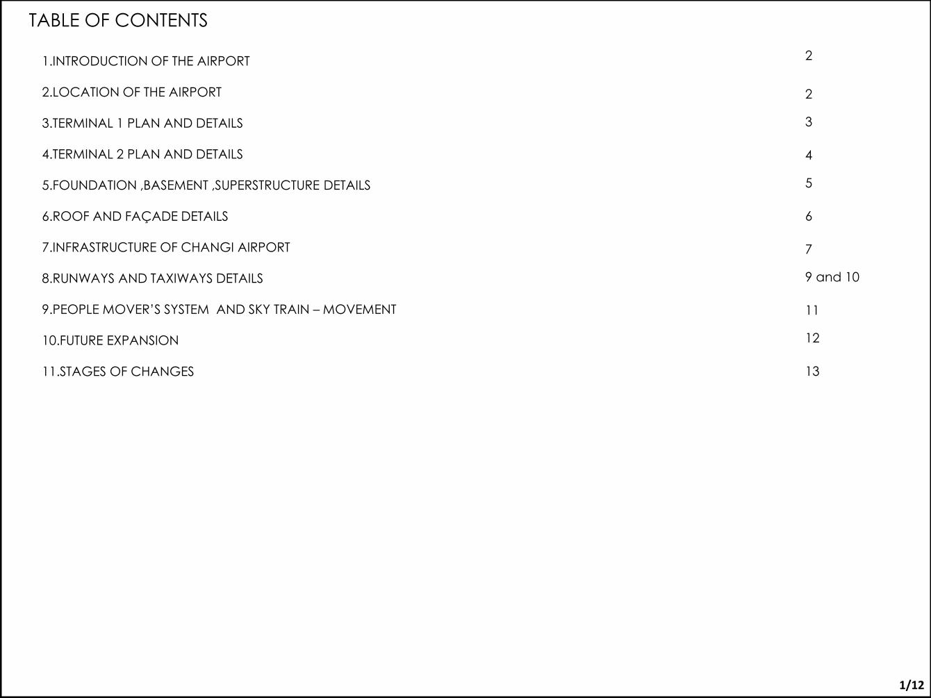
TABLE OF CONTENTS
1.INTRODUCTION OF THE AIRPORT
2.LOCATION OF THE AIRPORT 3.TERMINAL 1 PLAN AND DETAILS 4.TERMINAL 2 PLAN AND DETAILS 5.FOUNDATION ,BASEMENT ,SUPERSTRUCTURE DETAILS
6.ROOF AND FAÇADE DETAILS 7.INFRASTRUCTURE OF CHANGI AIRPORT 8.RUNWAYS AND TAXIWAYS DETAILS 9.PEOPLE MOVER’S SYSTEM AND SKY TRAIN – MOVEMENT 10.FUTURE EXPANSION
11.STAGES OF CHANGES
1/12
2
2
3
4
5
6
7
9 and 10
11
12
13
INTRODUCTION
• Singapore Changi Airport is a major aviation hub in Asia.
• It is located in Changi, about 20km east-north-east of Singapore centre.
• The airport is operated by the Changi Airport Group (CAG) of the Civil Aviation
Authority of Singapore (CAAS).
• The Singaporean Government made a decision to build Changi in 1975 following
congestion at the other airports in Singapore.
• Changi Airport has three passenger terminals with a total annual handling capacity of
66 million passengers. Terminal 1 opened in 1981, followed by Terminal 2 in 1990 and
Terminal 3 in 2008.
LOCATION • Changi Airport, is the primary civilian airport in the Republic of Singapore, and one of the
largest transportation hubs in Southeast Asia and the greater India region.
• The airport is located approximately 17.2 kilometres (10.7 mi) northeast from the
commercial centre in Changi, on a 13-square-kilometre (5.0 sq mi) site.
• By the 1970s Concerned that the existing airport was located in an area with potential
for urban growth, which would physically hem it in on all sides, the government
subsequently decided in 1975 to build a new airport at the eastern tip of the main island
at Changi, at the existing site of Changi Air Base, where the new airport would be easily
expandable through land reclamation.
PANAROMIC VIEW OF CHANGI AIRPORT-TERMINAL 1
VIEW OF CHANGI AIRPORT SHOWING CONTROL TOWER AND PARKING
PLAN SHOWING TERMINAL 1,2,3
LOCATION OF CHANGI AIRPORT IN SINGAPORE NIGHT VIEW OF CHANGI AIRPORT-CONTROL ROOM PASSENGER AIRLINE WITH COLUMNS 2/12
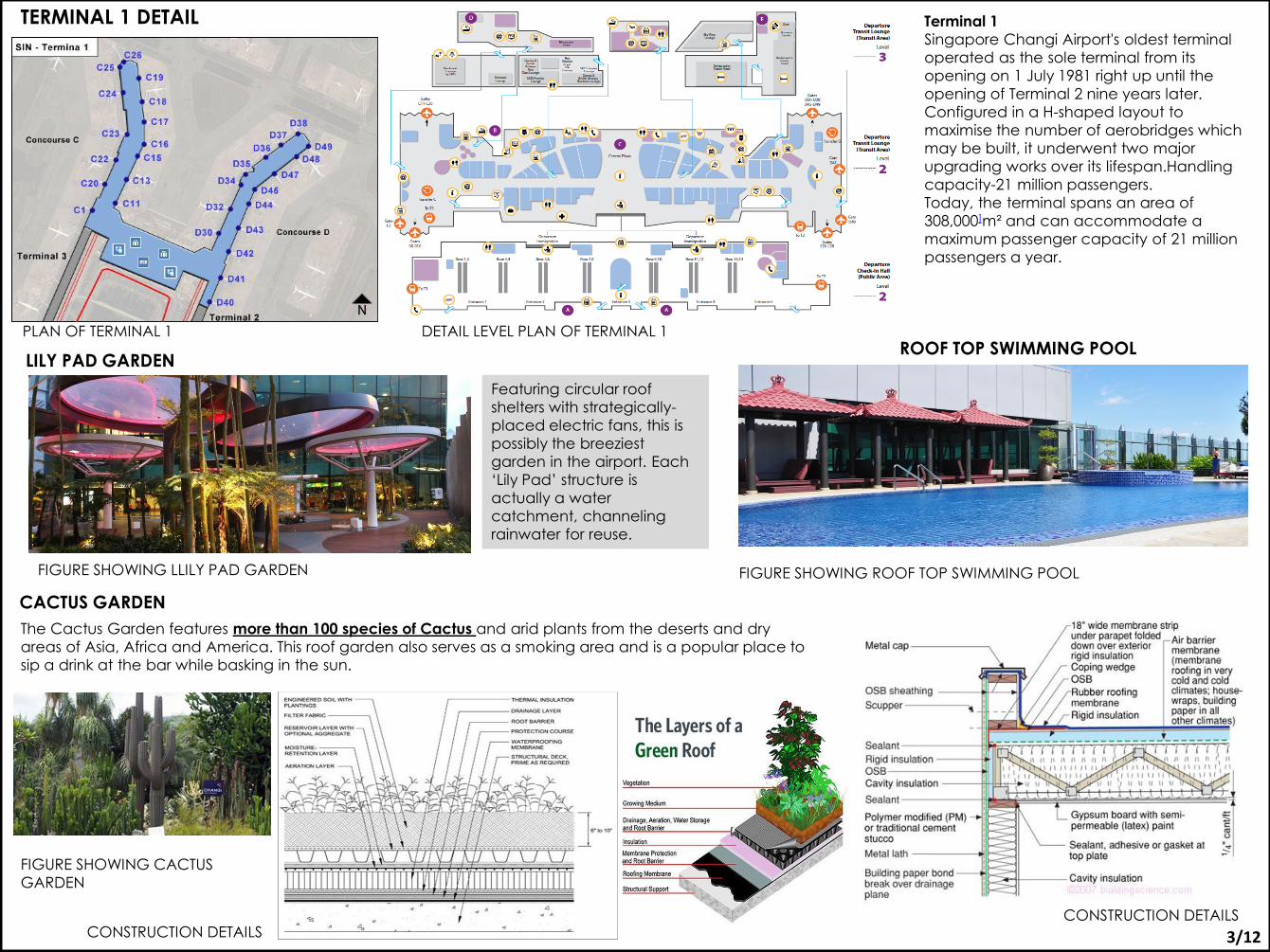
TERMINAL 1 DETAIL Terminal 1
Singapore Changi Airport's oldest terminal
operated as the sole terminal from its
opening on 1 July 1981 right up until the
opening of Terminal 2 nine years later.
Configured in a H-shaped layout to
maximise the number of aerobridges which
may be built, it underwent two major
upgrading works over its lifespan.Handling
capacity-21 million passengers.
Today, the terminal spans an area of
308,000]m² and can accommodate a
maximum passenger capacity of 21 million
passengers a year.
PLAN OF TERMINAL 1 DETAIL LEVEL PLAN OF TERMINAL 1
LILY PAD GARDEN
Featuring circular roof
shelters with strategically-
placed electric fans, this is
possibly the breeziest
garden in the airport. Each
‘Lily Pad’ structure is
actually a water
catchment, channeling
rainwater for reuse.
FIGURE SHOWING LLILY PAD GARDEN
ROOF TOP SWIMMING POOL
CONSTRUCTION DETAILS
CACTUS GARDEN
The Cactus Garden features more than 100 species of Cactus and arid plants from the deserts and dry
areas of Asia, Africa and America. This roof garden also serves as a smoking area and is a popular place to
sip a drink at the bar while basking in the sun.
FIGURE SHOWING CACTUS
GARDEN
CONSTRUCTION DETAILS
FIGURE SHOWING ROOF TOP SWIMMING POOL
3/12
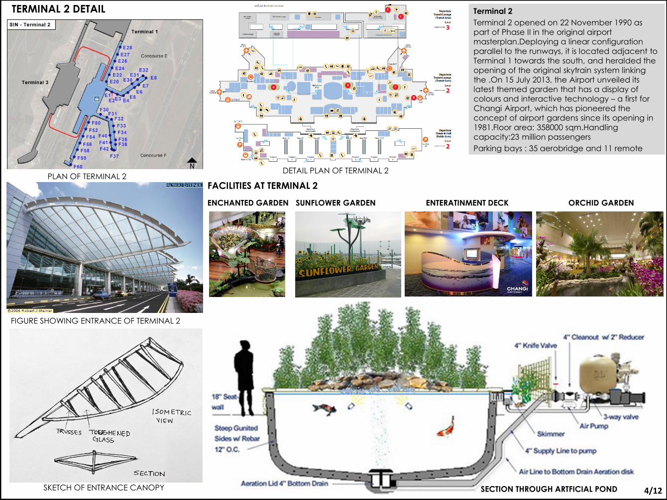
Terminal 2
Terminal 2 opened on 22 November 1990 as
part of Phase II in the original airport
masterplan.Deploying a linear configuration
parallel to the runways, it is located adjacent to
Terminal 1 towards the south, and heralded the
opening of the original skytrain system linking
the .On 15 July 2013, the Airport unveiled its
latest themed garden that has a display of
colours and interactive technology – a first for
Changi Airport, which has pioneered the
concept of airport gardens since its opening in
1981.Floor area: 358000 sqm.Handling
capacity:23 million passengers
Parking bays : 35 aerobridge and 11 remote
TERMINAL 2 DETAIL
PLAN OF TERMINAL 2 DETAIL PLAN OF TERMINAL 2
FIGURE SHOWING ENTRANCE OF TERMINAL 2
FACILITIES AT TERMINAL 2
ENCHANTED GARDEN
ORCHID GARDEN
SUNFLOWER GARDEN ENTERATINMENT DECK ORCHID GARDEN
SECTION THROUGH ARTFICIAL POND SKETCH OF ENTRANCE CANOPY 4/12
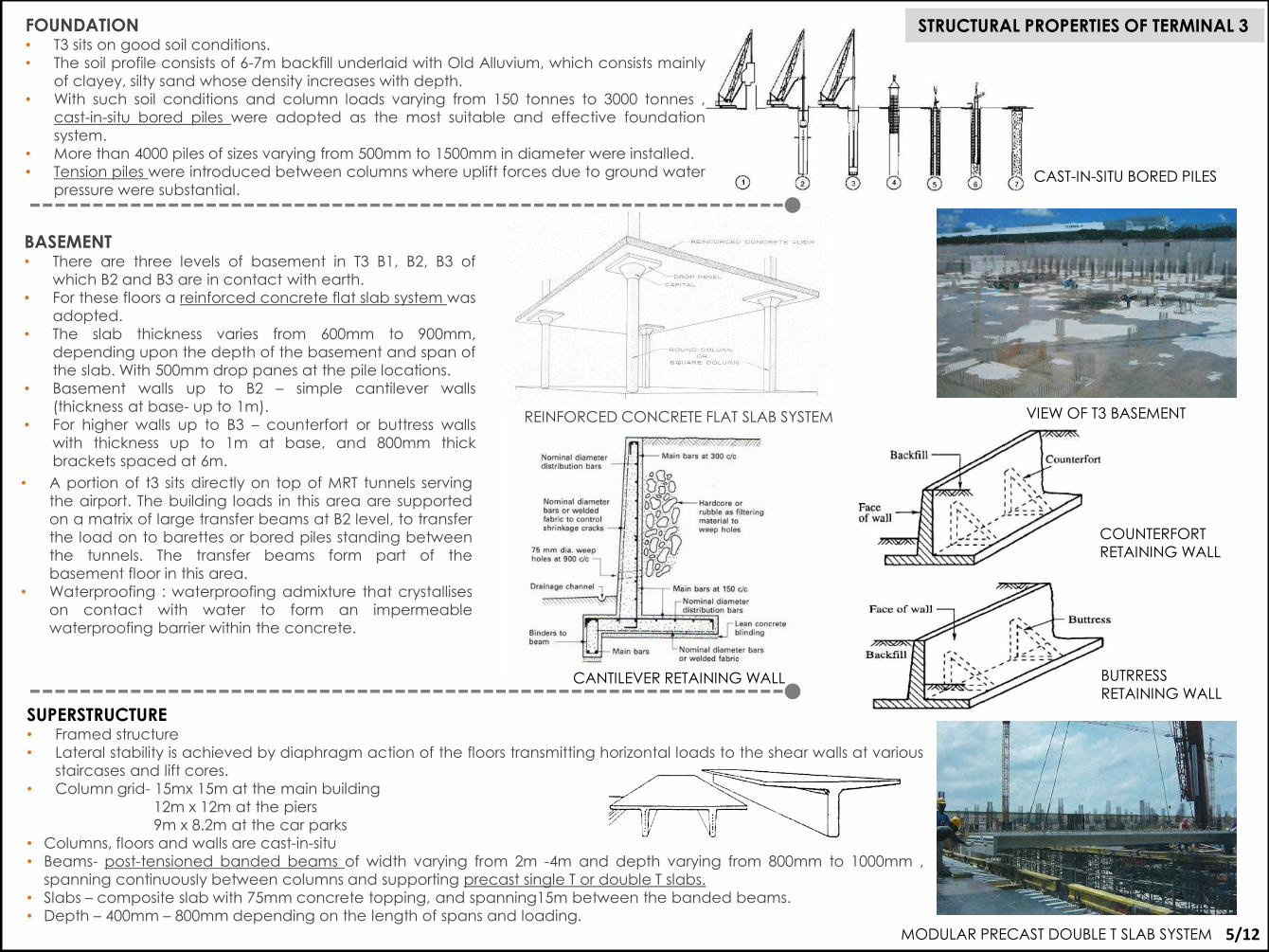
STRUCTURAL PROPERTIES OF TERMINAL 3
BASEMENT • There are three levels of basement in T3 B1, B2, B3 of
which B2 and B3 are in contact with earth.
• For these floors a reinforced concrete flat slab system was
adopted.
• The slab thickness varies from 600mm to 900mm,
depending upon the depth of the basement and span of
the slab. With 500mm drop panes at the pile locations.
• Basement walls up to B2 – simple cantilever walls
(thickness at base- up to 1m).
• For higher walls up to B3 – counterfort or buttress walls
with thickness up to 1m at base, and 800mm thick
brackets spaced at 6m.
REINFORCED CONCRETE FLAT SLAB SYSTEM
CANTILEVER RETAINING WALL
COUNTERFORT
RETAINING WALL
BUTRRESS
RETAINING WALL
• A portion of t3 sits directly on top of MRT tunnels serving
the airport. The building loads in this area are supported
on a matrix of large transfer beams at B2 level, to transfer
the load on to barettes or bored piles standing between
the tunnels. The transfer beams form part of the
basement floor in this area.
• Waterproofing : waterproofing admixture that crystallises
on contact with water to form an impermeable
waterproofing barrier within the concrete.
VIEW OF T3 BASEMENT
FOUNDATION • T3 sits on good soil conditions.
• The soil profile consists of 6-7m backfill underlaid with Old Alluvium, which consists mainly
of clayey, silty sand whose density increases with depth.
• With such soil conditions and column loads varying from 150 tonnes to 3000 tonnes ,
cast-in-situ bored piles were adopted as the most suitable and effective foundation
system.
• More than 4000 piles of sizes varying from 500mm to 1500mm in diameter were installed.
• Tension piles were introduced between columns where uplift forces due to ground water
pressure were substantial.
CAST-IN-SITU BORED PILES
SUPERSTRUCTURE • Framed structure
• Lateral stability is achieved by diaphragm action of the floors transmitting horizontal loads to the shear walls at various
staircases and lift cores.
• Column grid- 15mx 15m at the main building
12m x 12m at the piers
9m x 8.2m at the car parks
• Columns, floors and walls are cast-in-situ
• Beams- post-tensioned banded beams of width varying from 2m -4m and depth varying from 800mm to 1000mm ,
spanning continuously between columns and supporting precast single T or double T slabs.
• Slabs – composite slab with 75mm concrete topping, and spanning15m between the banded beams.
• Depth – 400mm – 800mm depending on the length of spans and loading.
MODULAR PRECAST DOUBLE T SLAB SYSTEM 5/12
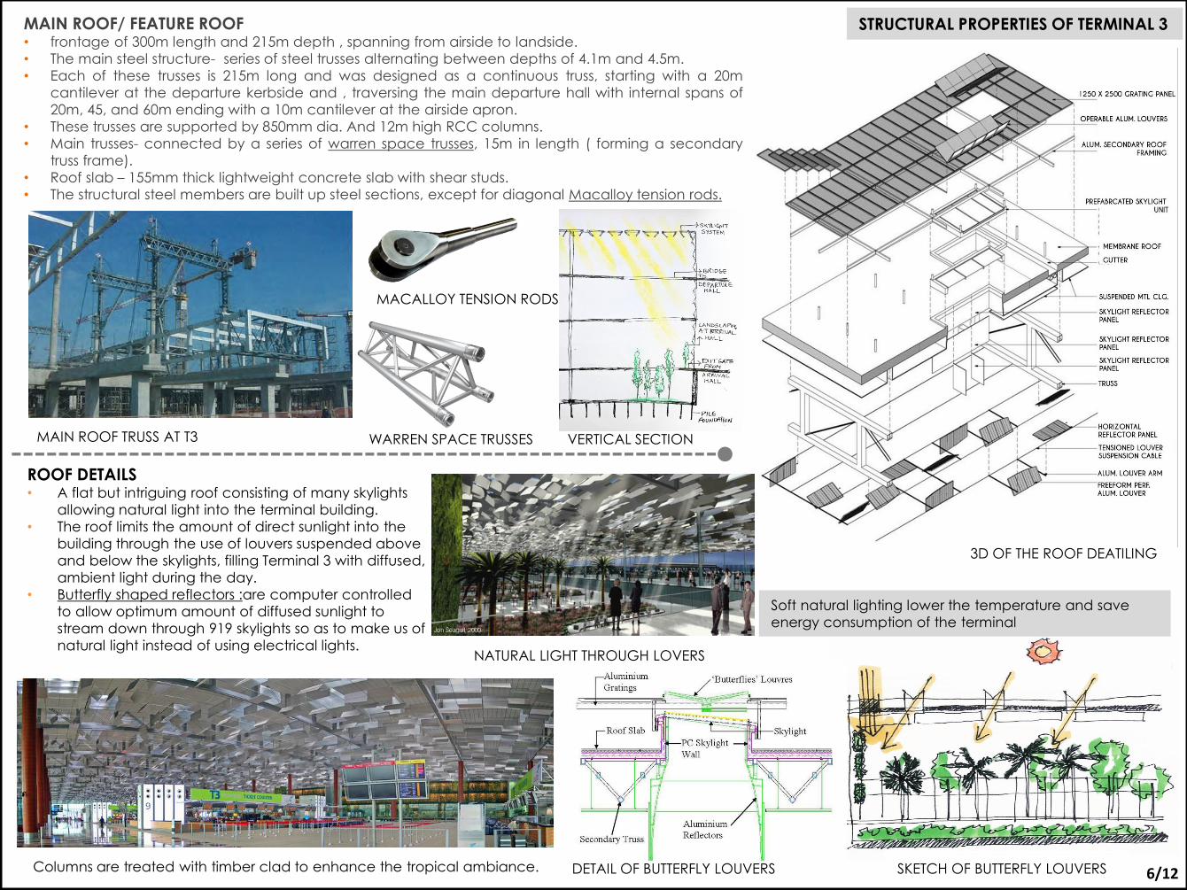
STRUCTURAL PROPERTIES OF TERMINAL 3 MAIN ROOF/ FEATURE ROOF • frontage of 300m length and 215m depth , spanning from airside to landside.
• The main steel structure- series of steel trusses alternating between depths of 4.1m and 4.5m.
• Each of these trusses is 215m long and was designed as a continuous truss, starting with a 20m
cantilever at the departure kerbside and , traversing the main departure hall with internal spans of
20m, 45, and 60m ending with a 10m cantilever at the airside apron.
• These trusses are supported by 850mm dia. And 12m high RCC columns.
• Main trusses- connected by a series of warren space trusses, 15m in length ( forming a secondary
truss frame).
• Roof slab – 155mm thick lightweight concrete slab with shear studs.
• The structural steel members are built up steel sections, except for diagonal Macalloy tension rods.
MAIN ROOF TRUSS AT T3
MACALLOY TENSION RODS
ROOF DETAILS • A flat but intriguing roof consisting of many skylights
allowing natural light into the terminal building.
• The roof limits the amount of direct sunlight into the
building through the use of louvers suspended above
and below the skylights, filling Terminal 3 with diffused,
ambient light during the day.
• Butterfly shaped reflectors :are computer controlled
to allow optimum amount of diffused sunlight to
stream down through 919 skylights so as to make us of
natural light instead of using electrical lights.
Soft natural lighting lower the temperature and save
energy consumption of the terminal
Columns are treated with timber clad to enhance the tropical ambiance.
NATURAL LIGHT THROUGH LOVERS
DETAIL OF BUTTERFLY LOUVERS SKETCH OF BUTTERFLY LOUVERS
3D OF THE ROOF DEATILING
WARREN SPACE TRUSSES VERTICAL SECTION
6/12
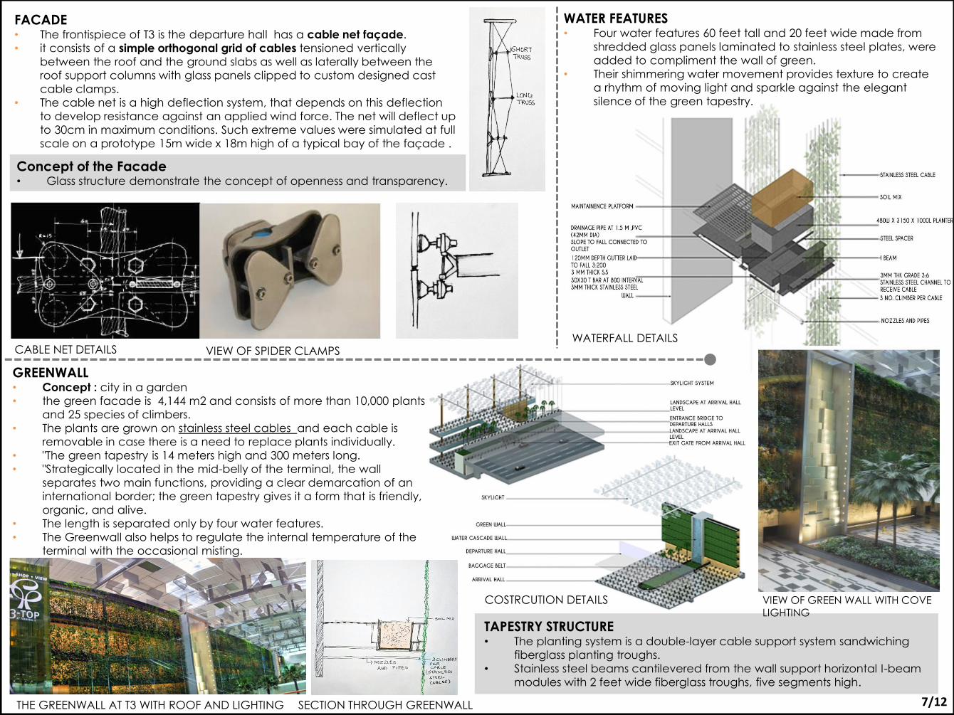
Concept of the Facade • Glass structure demonstrate the concept of openness and transparency.
FACADE • The frontispiece of T3 is the departure hall has a cable net façade.
• it consists of a simple orthogonal grid of cables tensioned vertically
between the roof and the ground slabs as well as laterally between the
roof support columns with glass panels clipped to custom designed cast
cable clamps.
• The cable net is a high deflection system, that depends on this deflection
to develop resistance against an applied wind force. The net will deflect up
to 30cm in maximum conditions. Such extreme values were simulated at full
scale on a prototype 15m wide x 18m high of a typical bay of the façade .
CABLE NET DETAILS
GREENWALL • Concept : city in a garden
• the green facade is 4,144 m2 and consists of more than 10,000 plants
and 25 species of climbers.
• The plants are grown on stainless steel cables and each cable is
removable in case there is a need to replace plants individually.
• "The green tapestry is 14 meters high and 300 meters long.
• "Strategically located in the mid-belly of the terminal, the wall
separates two main functions, providing a clear demarcation of an
international border; the green tapestry gives it a form that is friendly,
organic, and alive.
• The length is separated only by four water features.
• The Greenwall also helps to regulate the internal temperature of the
terminal with the occasional misting.
THE GREENWALL AT T3 WITH ROOF AND LIGHTING SECTION THROUGH GREENWALL
COSTRCUTION DETAILS
TAPESTRY STRUCTURE • The planting system is a double-layer cable support system sandwiching
fiberglass planting troughs.
• Stainless steel beams cantilevered from the wall support horizontal I-beam
modules with 2 feet wide fiberglass troughs, five segments high.
WATER FEATURES • Four water features 60 feet tall and 20 feet wide made from
shredded glass panels laminated to stainless steel plates, were
added to compliment the wall of green.
• Their shimmering water movement provides texture to create
a rhythm of moving light and sparkle against the elegant
silence of the green tapestry.
WATERFALL DETAILS
7/12
VIEW OF SPIDER CLAMPS
VIEW OF GREEN WALL WITH COVE LIGHTING
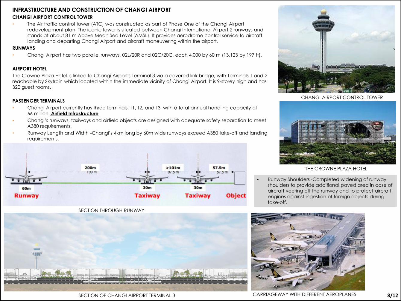
INFRASTRUCTURE AND CONSTRUCTION OF CHANGI AIRPORT
CHANGI AIRPORT CONTROL TOWER
• The Air traffic control tower (ATC) was constructed as part of Phase One of the Changi Airport
redevelopment plan. The iconic tower is situated between Changi International Airport 2 runways and
stands at about 81 m Above Mean Sea Level (AMSL). It provides aerodrome control service to aircraft
landing and departing Changi Airport and aircraft maneuvering within the airport.
RUNWAYS
• Changi Airport has two parallel runways, 02L/20R and 02C/20C, each 4,000 by 60 m (13,123 by 197 ft).
AIRPORT HOTEL
The Crowne Plaza Hotel is linked to Changi Airport's Terminal 3 via a covered link bridge, with Terminals 1 and 2
reachable by Skytrain which located within the immediate vicinity of Changi Airport. lt is 9-storey high and has
320 guest rooms.
PASSENGER TERMINALS
• Changi Airport currently has three terminals, T1, T2, and T3, with a total annual handling capacity of
66 million. Airfield Infrastructure
• Changi’s runways, taxiways and airfield objects are designed with adequate safety separation to meet
A380 requirements.
• Runway Length and Width -Changi’s 4km long by 60m wide runways exceed A380 take-off and landing
requirements.
CHANGI AIRPORT CONTROL TOWER
THE CROWNE PLAZA HOTEL
• Runway Shoulders -Completed widening of runway
shoulders to provide additional paved area in case of
aircraft veering off the runway and to protect aircraft
engines against ingestion of foreign objects during
take-off.
SECTION OF CHANGI AIRPORT TERMINAL 3
SECTION THROUGH RUNWAY
8/12 CARRIAGEWAY WITH DIFFERENT AEROPLANES
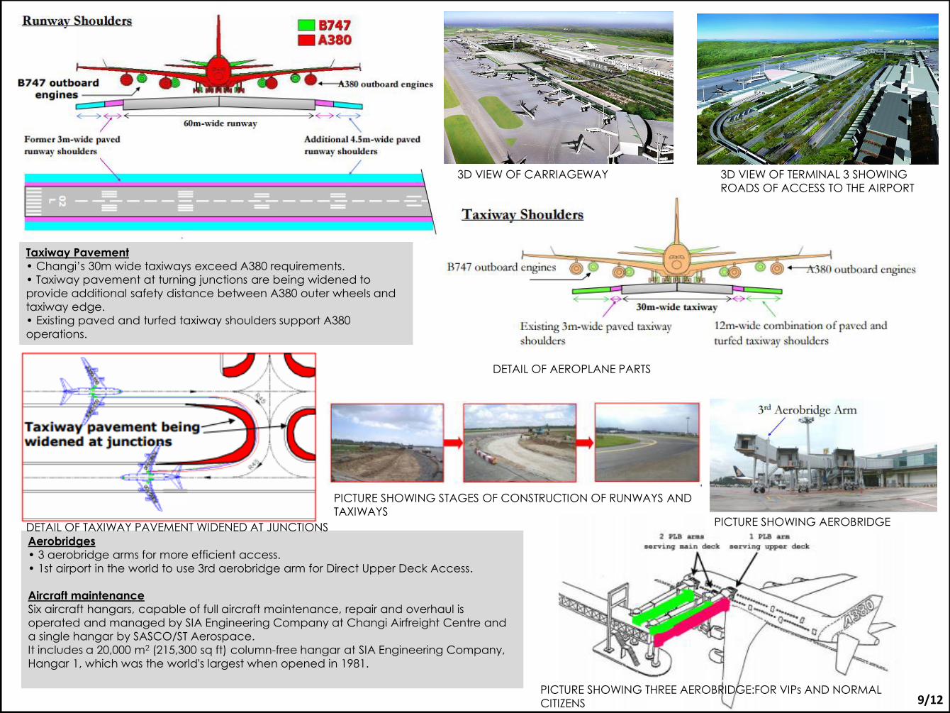
Taxiway Pavement
• Changi’s 30m wide taxiways exceed A380 requirements.
• Taxiway pavement at turning junctions are being widened to
provide additional safety distance between A380 outer wheels and
taxiway edge.
• Existing paved and turfed taxiway shoulders support A380
operations.
Aerobridges
• 3 aerobridge arms for more efficient access.
• 1st airport in the world to use 3rd aerobridge arm for Direct Upper Deck Access.
Aircraft maintenance
Six aircraft hangars, capable of full aircraft maintenance, repair and overhaul is
operated and managed by SIA Engineering Company at Changi Airfreight Centre and
a single hangar by SASCO/ST Aerospace.
It includes a 20,000 m2 (215,300 sq ft) column-free hangar at SIA Engineering Company,
Hangar 1, which was the world's largest when opened in 1981.
9/12
3D VIEW OF CARRIAGEWAY 3D VIEW OF TERMINAL 3 SHOWING
ROADS OF ACCESS TO THE AIRPORT
PICTURE SHOWING STAGES OF CONSTRUCTION OF RUNWAYS AND
TAXIWAYS PICTURE SHOWING AEROBRIDGE
DETAIL OF AEROPLANE PARTS
DETAIL OF TAXIWAY PAVEMENT WIDENED AT JUNCTIONS
PICTURE SHOWING THREE AEROBRIDGE:FOR VIPs AND NORMAL
CITIZENS
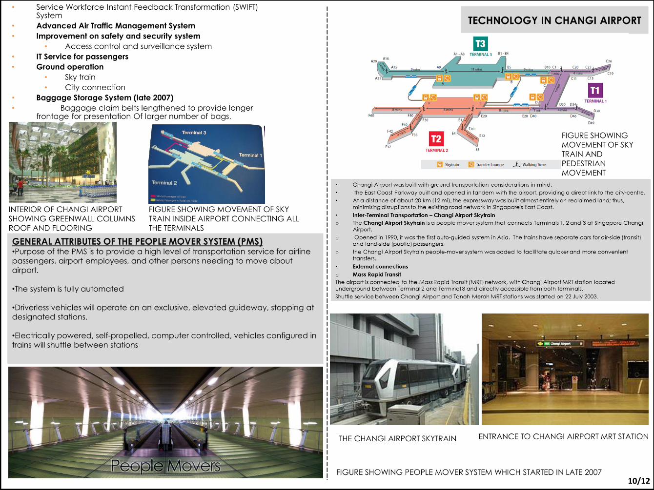
TECHNOLOGY IN CHANGI AIRPORT
• Service Workforce Instant Feedback Transformation (SWIFT) System
• Advanced Air Traffic Management System
• Improvement on safety and security system
• Access control and surveillance system
• IT Service for passengers
• Ground operation
• Sky train
• City connection
• Baggage Storage System (late 2007)
• Baggage claim belts lengthened to provide longer frontage for presentation Of larger number of bags.
GENERAL ATTRIBUTES OF THE PEOPLE MOVER SYSTEM (PMS) •Purpose of the PMS is to provide a high level of transportation service for airline
passengers, airport employees, and other persons needing to move about
airport.
•The system is fully automated
•Driverless vehicles will operate on an exclusive, elevated guideway, stopping at
designated stations.
•Electrically powered, self-propelled, computer controlled, vehicles configured in
trains will shuttle between stations
THE CHANGI AIRPORT SKYTRAIN ENTRANCE TO CHANGI AIRPORT MRT STATION
FIGURE SHOWING PEOPLE MOVER SYSTEM WHICH STARTED IN LATE 2007 10/12
INTERIOR OF CHANGI AIRPORT
SHOWING GREENWALL COLUMNS
ROOF AND FLOORING
FIGURE SHOWING MOVEMENT OF SKY
TRAIN INSIDE AIRPORT CONNECTING ALL
THE TERMINALS
FIGURE SHOWING
MOVEMENT OF SKY
TRAIN AND
PEDESTRIAN
MOVEMENT
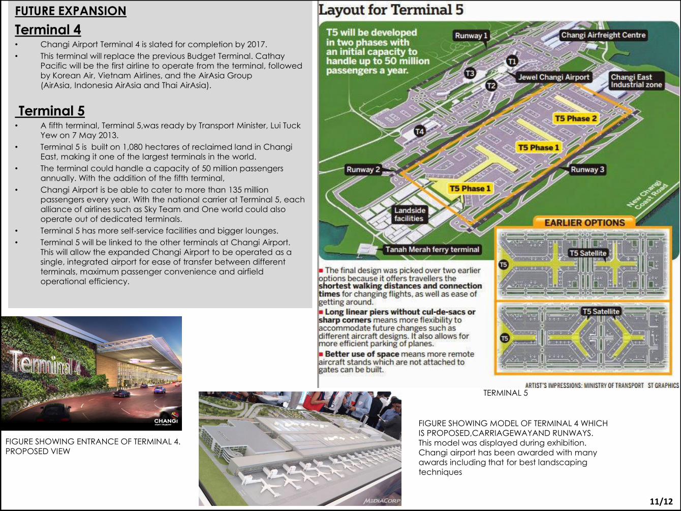
FUTURE EXPANSION
Terminal 4 • Changi Airport Terminal 4 is slated for completion by 2017.
• This terminal will replace the previous Budget Terminal. Cathay
Pacific will be the first airline to operate from the terminal, followed
by Korean Air, Vietnam Airlines, and the AirAsia Group
(AirAsia, Indonesia AirAsia and Thai AirAsia).
Terminal 5 • A fifth terminal, Terminal 5,was ready by Transport Minister, Lui Tuck
Yew on 7 May 2013.
• Terminal 5 is built on 1,080 hectares of reclaimed land in Changi
East, making it one of the largest terminals in the world.
• The terminal could handle a capacity of 50 million passengers
annually. With the addition of the fifth terminal,
• Changi Airport is be able to cater to more than 135 million
passengers every year. With the national carrier at Terminal 5, each
alliance of airlines such as Sky Team and One world could also
operate out of dedicated terminals.
• Terminal 5 has more self-service facilities and bigger lounges.
• Terminal 5 will be linked to the other terminals at Changi Airport.
This will allow the expanded Changi Airport to be operated as a
single, integrated airport for ease of transfer between different
terminals, maximum passenger convenience and airfield
operational efficiency.
TERMINAL 5
FIGURE SHOWING MODEL OF TERMINAL 4 WHICH
IS PROPOSED,CARRIAGEWAYAND RUNWAYS.
This model was displayed during exhibition.
Changi airport has been awarded with many
awards including that for best landscaping
techniques
11/12
FIGURE SHOWING ENTRANCE OF TERMINAL 4.
PROPOSED VIEW
Changes Stage 2: 21/10/2015
1.Font size -12 heading- 14
2.Mark all pictures with arrows and headings
3.Vertical and horizontal sections and sketches
4.Truss details
5.Roof details
6.Façade details
7.Foundation,basement and superstructure details
Changes Stage 1 : 7/10/2015
1.Font size -14 heading-16
2.Less font
3.More pictures
4.Detail of runway,carriageway,taxiway
5.Add more information
Changes Stage 3: 28/10/2015
1.Mark all pictures
2.Sheet numbers
3.Photographs of all group members
DONE
12/12
REFERENCES 1. MEDIA RELEASE 2012 CHANGI IMPROVEMENTS 2. ANNUAL REPORT CHANGI AIRPORT 3. CASE STUDY BY TRIDIUM OF CHANGI AIRPORT 4. CRISPLANT PDF OF CHANGI AIRPORT 5. HAD FAÇADE WORKING OF CHANGI AIRPORT 6. GO DIGITAL AT CHANGI AIRPORT 7. PRESSEM DULNGUM-CHANGI AIRPORT
8. YUN PRESENTATION OF CHANGI AIRPORT 9. www.changiairport.com 10. www.spiderclampsmuhgy.org 11.www.interiorglass.org 12.www.flooringchangi.org