Embed Size (px)
Citation preview

decoder
1

Video https://www.youtube.com/w
atch?v=DgVkEVI6_Ws
2

Combinational Logic Decoders
A decoder is a logic circuit that detects the presence of a specific combination of
bits at its input. Two simple decoders that detect the presence of the binary code
0011 are shown. The first has an active HIGH output; the second has an active
LOW output.
EXAMPLE:
Assume the output of the decoder shown is a logic 1. What are the inputs to the
decoder?
32
3
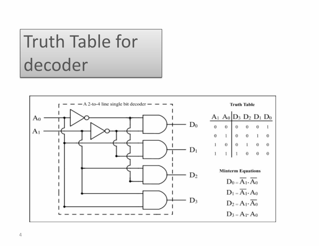
Truth Table for decoder
4
Combinational Logic Decoders
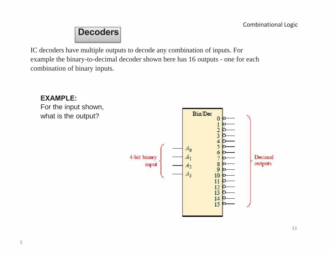
IC decoders have multiple outputs to decode any combination of inputs. For
example the binary-to-decimal decoder shown here has 16 outputs - one for each
combination of binary inputs.
EXAMPLE:
For the input shown,
what is the output?
33
5
Combinational Logic Decoders
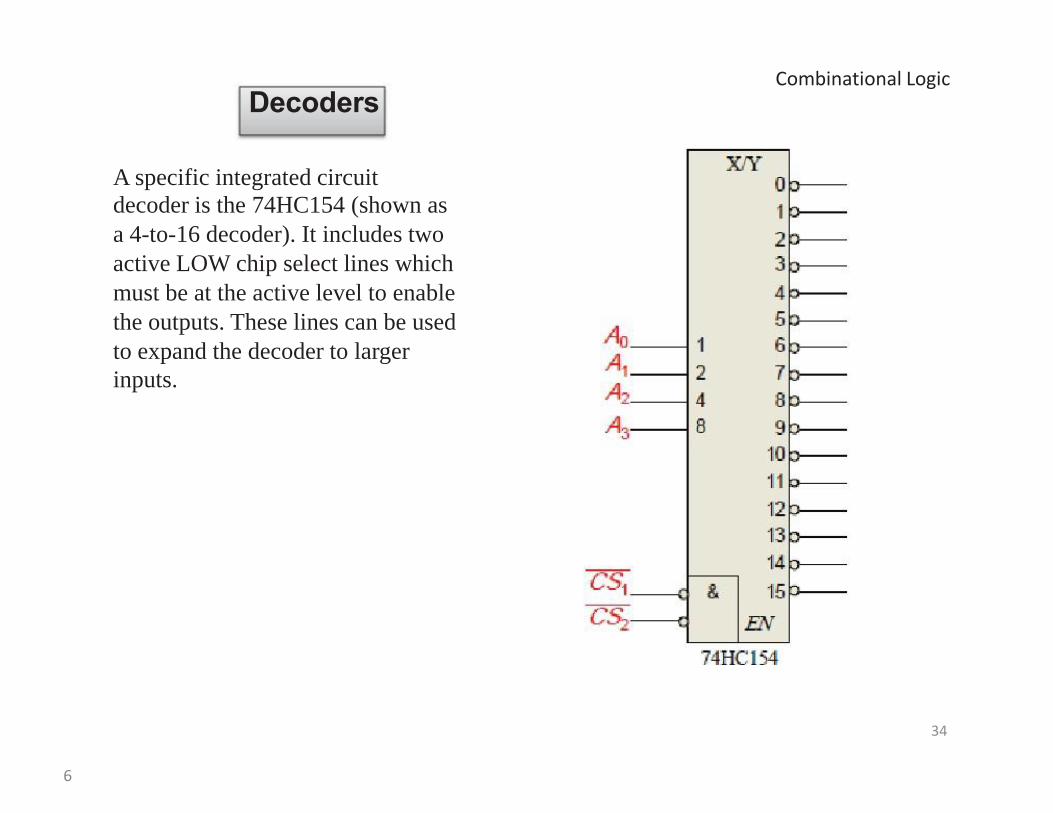
A specific integrated circuit decoder is the 74HC154 (shown as
a 4-to-16 decoder). It includes two
active LOW chip select lines which
must be at the active level to enable
the outputs. These lines can be used
to expand the decoder to larger
inputs.
34
6

Combinational Logic Decoders
BCD-to-decimal decoders accept a binary
coded decimal input and activate one of ten
possible decimal digit indications.
EXAMPLE:
Assume the inputs to the 74HC42 decoder are the sequence 0101, 0110,
0011, and 0010. Describe the output.
36
7

Combinational Logic MultiSim Experiment: Decoders
The 74LS138 is a 3-to-8 decoder with three chip select inputs (two active LOW, one
active HIGH). In this Multisim circuit, the word generator (XWG1) is set up as an
up counter. The logic analyzer (XLA1) compares the input and outputs of the
decoder.
35
8
Combinational Logic BCD Decoder/Driver
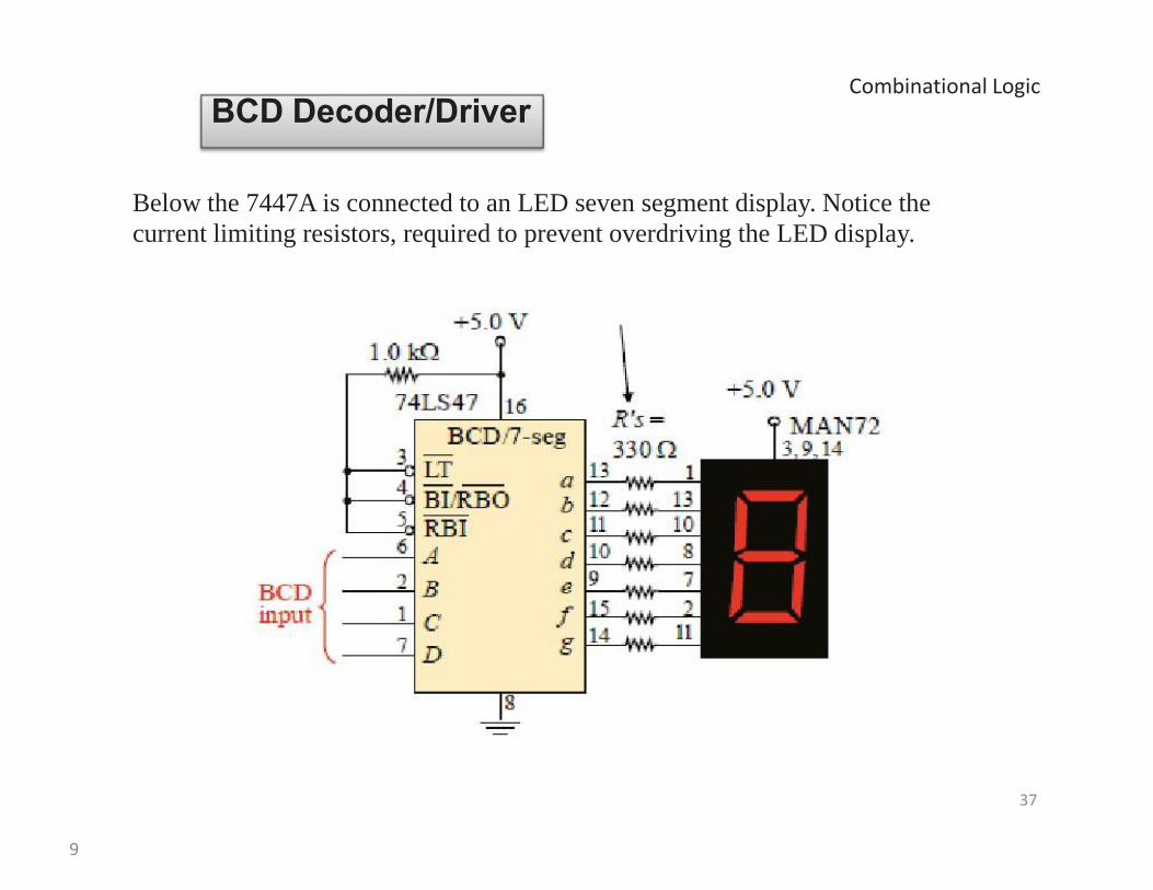
Below the 7447A is connected to an LED seven segment display. Notice the
current limiting resistors, required to prevent overdriving the LED display.
37
9
Combinational Logic BCD Decoder/Driver
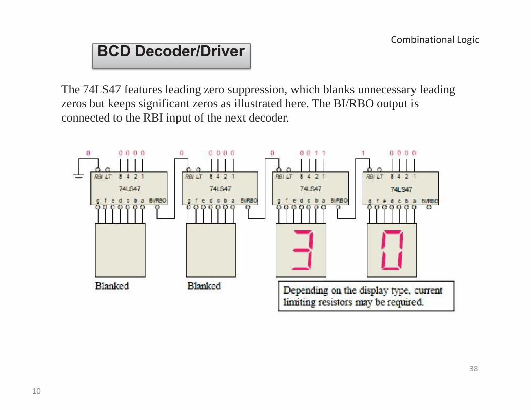
The 74LS47 features leading zero suppression, which blanks unnecessary leading
zeros but keeps significant zeros as illustrated here. The BI/RBO output is
connected to the RBI input of the next decoder.
38
10
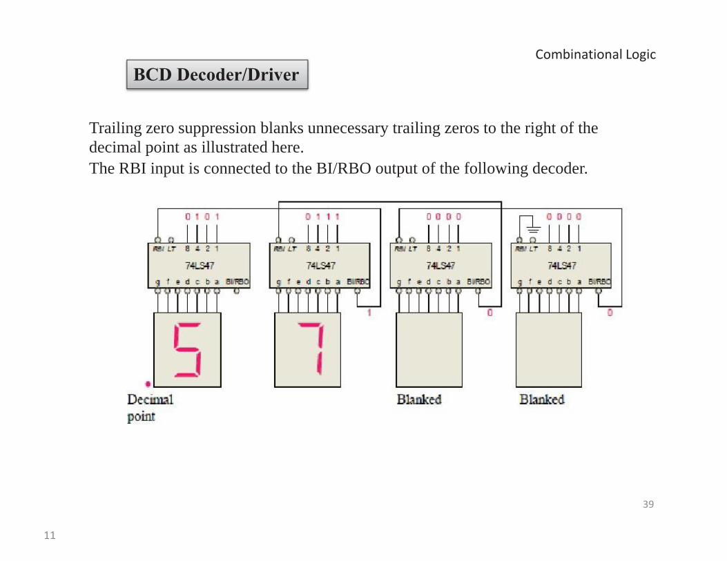
Combinational Logic BCD Decoder/Driver
Trailing zero suppression blanks unnecessary trailing zeros to the right of the
decimal point as illustrated here. The RBI input is connected to the BI/RBO output of the following decoder.
39
11
Practical work
12

Summary
13