Embed Size (px)
Citation preview
Vale
Company Advisor: Dr. Vladimir PaserinFaculty Advisor: Dr. Gu Xu
Catherine PereiraAbrar Sidahmed Catherine Silva

• Overview of Process
• Problem Statement
• Engineering Analysis
▫ Optical Microscope
▫ Compositional/EDS Analysis
▫ Distribution of Impurities
▫ EBSD Analysis
• Sustainability & Economic Issues
• Conclusion
• References
2
Outline
MATLS 4Z06 - VALE

Overview of Process
• Nickel carbonyl pellet decomposer
3
MATLS 4Z06 - VALEImage from: "Carbonyl Refining of Impure Nickel Metal," in Extractive Metallurgy of Nickel, Cobalt and Platinum-Group Metals.: Elsevier Ltd., 2011, ch. Chapter
22, pp. 269-280.
Fig 1: Pellet decomposer.

4
Problem Statement
• Two types of Pellets
▫ Sulphur (S-) Pellets , ~0.0220-0.0300 wt% S
▫ Plating (P-) Pellets, <0.0002 wt% S
• Both types of pellets experience rare
breaking of layer(s) („rattlers‟)
• Broken layers may affect the uniformity of
pellet dissolution
• Detecting trace amounts of impurities within
layers
• Attempt to relate process conditions to layer
formationMATLS 4Z06 - VALE

5
0% 100%
Fig2 : Measurements of broken layers in rattler.
Broken Layers

Broken Layers
6
- Presence of either one or two broken layer(s)
- Consistent location of layers within pellet
- Outer broken layer observed at the onset of grinding
- Inner broken layer starts to form after the pellet is
ground past half of its original size
Location:
OUTER LAYER AVG: ~ 81% of radius
INNER LAYER AVG: ~ 41% of radius
(0% = centre; 100% outer edge)
MATLS 4Z06 - VALE

• Average thickness of gap: 80-115 microns
• Average thickness of layers: (20-50 microns as stated by
Vale)
▫ Measured and calculated avg. of 30. 7 ± 9.5 microns
▫ Largest thickness 95 microns
• Average number of layers ~ 161 for rattlers
7
MATLS 4Z06 - VALE
Fig 3: Micrograph showing broken layer and onion structure of pellet.

Sample Preparation• Cold mounted rattler & normal pellets in epoxy
• Used 320, 400, 600 and 1200 SiC to grind pellets
down to a cross-sectional area
• Polishing: 6 micron, 1 micron diamond polish
followed by colloidal silica
• Etching: 10mL distilled water, 38mL nitric acid, 50mL
acetic acid.
▫ Normal pellets: submerged for 15 sec and 10 sec
▫ Rattler pellets: submerged for 8 sec and 5 sec
8
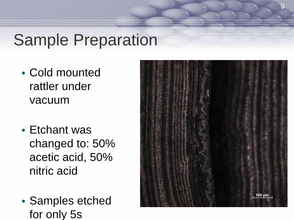
Sample Preparation
• Cold mounted
rattler under
vacuum
• Etchant was
changed to: 50%
acetic acid, 50%
nitric acid
• Samples etched
for only 5s
9
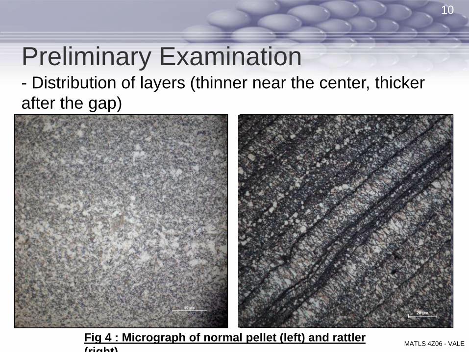
Preliminary Examination - Distribution of layers (thinner near the center, thicker
after the gap)
- Fine grained-structure
-
10
MATLS 4Z06 - VALEFig 4 : Micrograph of normal pellet (left) and rattler
(right).

Description of Layers in Rattler
LEGEND:
Yellow – „good
layers‟
White – „bad layers‟
Blue – „bad sub-
layers‟
Red – interfaces
Fig5 : Optical micrograph of rattler layers. x1000
mag.
11
MATLS 4Z06 - VALE

• Uneven surface protrusions
• Rough areas may be broken layer pieces that adhered to surface as pellet is recycled through process
12
Sectioning of Pellet
MATLS 4Z06 - VALEFig6 : Optical micrograph of surface of inner
centre.

Initial Compositional Analysis
• Carbon/sulfur analysis
• Limit stated by Vale
▫ UK plant standards
• Normal pellets studied meet limit for C for P-
pellet, but exceeds S-content
• Rattlers contain high C/S-content suggesting it
may be S-pellets
Element Normal Rattler (Inner) Rattler (Outer) Rattler Total
C (wt%) 0.0125 0.0167 0.0522 0.0345
S (wt%) 0.0036 0.0361 0.0508 0.0435
Element P-pellet S-pellet
C (wt%) < 0.0150 < 0.0050
S (wt%) < 0.0002 0.0220-0.0300
13
MATLS 4Z06 - VALE
Table 2 : Average results from C/S analysis.
Table 1: Compositional limits from Vale.

SEM Analysis
14

Structure of Normal Pellet
Normal Pellet: faceted/polygonal grains
15
MATLS 4Z06 - VALE
x5200
Mag.

Structure of Rattler
Grain Size/Distribution: bi-modal
16
MATLS 4Z06 - VALE
17
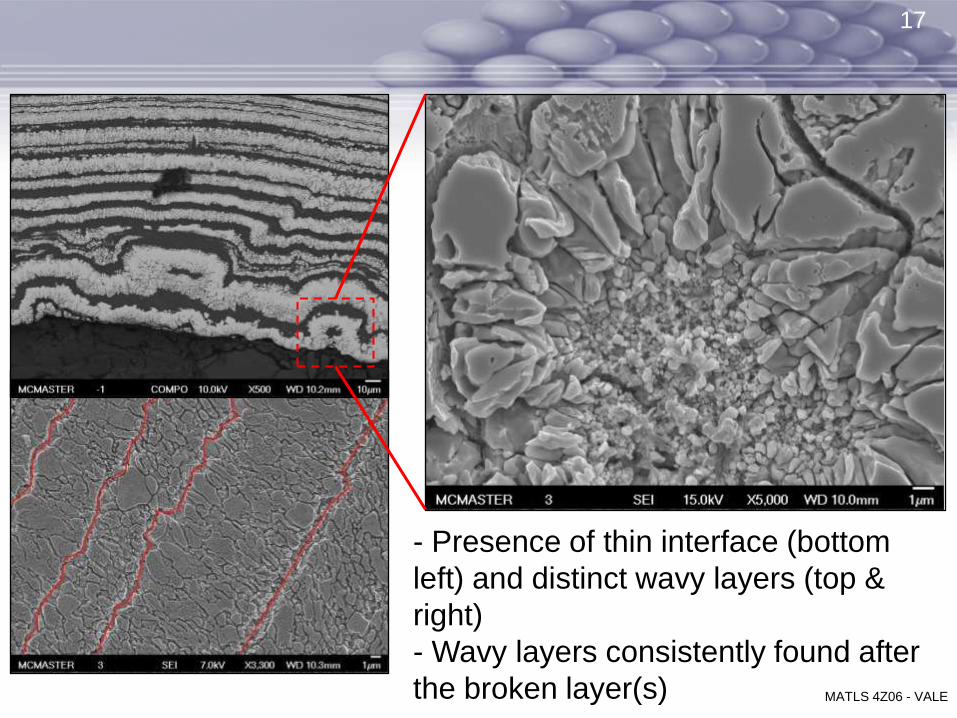
- Presence of thin interface (bottom
left) and distinct wavy layers (top &
right)
- Wavy layers consistently found after
the broken layer(s) MATLS 4Z06 - VALE

• Cross section analysis across entire diameter• Composition points taken every 200 microns• Slightly higher distribution of minor impurities
(C, Fe, Al, etc.) towards the centre as opposed to the edge of the pellet (not included in the table above)
EDS Analysis: Normal Pellet
Element Wt %
Ni 99.48
O 0.52
18
MATLS 4Z06 - VALE
Table 2 : Average EDS results for normal pellet.

● ● ●
Inner Surface of Outer Shell
19
● ● ●
Element Weight %
C 16.40
O 6.97
Fe 2.93
Ni 73.50
Element Weight %
C 13.39
O 0.64
Si 0.43
Ni 85.54

Element Weight%C 9.76S 0.82Ni 89.42
Totals 100.00
Element Weight%
C 29.37O 14.55Al 2.95Si 3.04K 4.39Ni 41.64
Totals 100.00
Element Weight%C 68.08O 11.96Na 1.59Al 0.50S 1.00Cl 2.28K 2.89Ni 11.71
Totals 100.00
Element Weight%
C 25.36O 34.79Al 4.44Si 5.98K 0.53Ni 28.90
Totals 100.00
A B
C D
Outer Surface of Inner Centre Part
20
Marker measures A) 50 um; B) 100 um; C) 10 um; D) 50um. MATLS 4Z06 - VALE

● ● ● ●
Rattler Pellet
Average composition of ‘good layer’:
Element Weight %
C 1.76
Ni 98.24
Average composition of ‘good’
interface:Element Weight %
C 0.76
Ni 99.24
●●● ●● ●
21
MATLS 4Z06 - VALE
Table 3 : Average EDS results for rattler.
Table 4: Average EDS results rattler.

Rattler PelletAverage composition of ‘wavy layer/
interface’:Element Weight %
C 10.78
O 3.78
Al 0.10
Si 0.13
S 2.41
Cl 0.05
Fe 0.80
Ni 81.95
●
●
●
●
Average composition of ‘bad
layer/interface’ :Element Weight %
C 1.98
O 5.27
Ni 92.76
22
MATLS 4Z06 - VALE
Table 5: Average EDS results rattler.
Table 6: Average EDS results rattler.

Distribution of Impurities
Fig 7: Element distribution across layers in rattler.
1) Original SEM image; 2) C distribution; 3) O distribution; 4) S
distribution
23
MATLS 4Z06 - VALE

EBSD Analysis
24

25
=50 µm; Map1; Step=0.5 µm; Grid386x93
• Other reason for unique etching: difference in grain orientation
• Shows inhomogeneous structure with bands of small and large grains
• Has a higher proportion of Σ3 boundaries
Σ3 Boundary
Σ9 Boundary
Low Angle
Boundary
High Angle
Boundary
Normal/High Sulphur Content Pellet
Results
• Data provided by Valerie Randle, Vale.
MATLS 4Z06 - VALE

2626
Rattler Pellet Results Σ3 Boundary
Σ9 Boundary
Low Angle
Boundary
Grain Boundary
• Grain Boundaries
• Has a higher proportion of Σ3 boundaries, more
specifically after gap
MATLS 4Z06 - VALE

2727
Rattler Pellet Results• Local Misorientation
Misoriented
Grains
MAD: 0.61°
MATLS 4Z06 - VALE

2828
Rattler Pellet Results
MATLS 4Z06 - VALE
• Smaller grains
before gap, and
larger ones after
gap
• Grain size range:
0.2-13 microns
• Grain size avg.
0.8 microns

Role of Impurities
• Preferential etching in rattler not seen with normal pellet:
▫ At „good‟ interface – due to local misorientations
▫ At „bad layer/interface‟ – oxygen impurities distributed within those region
• ‘Wavy layer’ formation
▫ Due to high content of impurities: oxygen and carbon
There is a higher surface roughness and poor adhesion
29
MATLS 4Z06 - VALE

Source of the Problem
• Layers break
▫ Impurities affect quality of deposited nickel:
non uniform thickness, weaker adherence
to substrate
▫ Higher proportion of twinning suggests high
internal stresses built in during growth
▫ Combination of above promotes cracking
30
MATLS 4Z06 - VALE

Source of the Problem
31
- Thickness of gap is large
(~80 - 115 um) suggests
multiple layers are fracturing
- Occasionally, a full broken
layer does not form
Fig 8: (Right): Semi- broken
layers
- Very dark bands with thin
layers are suggested to be
susceptible to fracture and
breaking
Fig 9: (Left): Dark wavy Ni bands MATLS 4Z06 - VALE

32
Source of the Problem
GAPGAP
MATLS 4Z06 - VALE
Evidence of beginning of
broken layer at ‘wavy’
layers

Relation to Process: Sulphur• S-pellet
▫ Evenly distributed sulphur content
▫ Higher sulphur content than
originally expected
▫ Possibly large temperature
gradient induces turbulence on
the substrate
▫ Does not contribute to the
observed dissolution behaviour
33
MATLS 4Z06 - VALE

Relation to Process: Oxygen
• Oxidation/contamination of nickel surface as
pellet travels through bucket elevator
• Exposure of oxygen from make-vessel or during
maintenance of reaction chamber
• Occurs at bad interfaces of thinner layers and
becomes preferentially etched
▫ Not present in high amounts
▫ Hinders the deposition/growth of Ni layer
34
MATLS 4Z06 - VALE
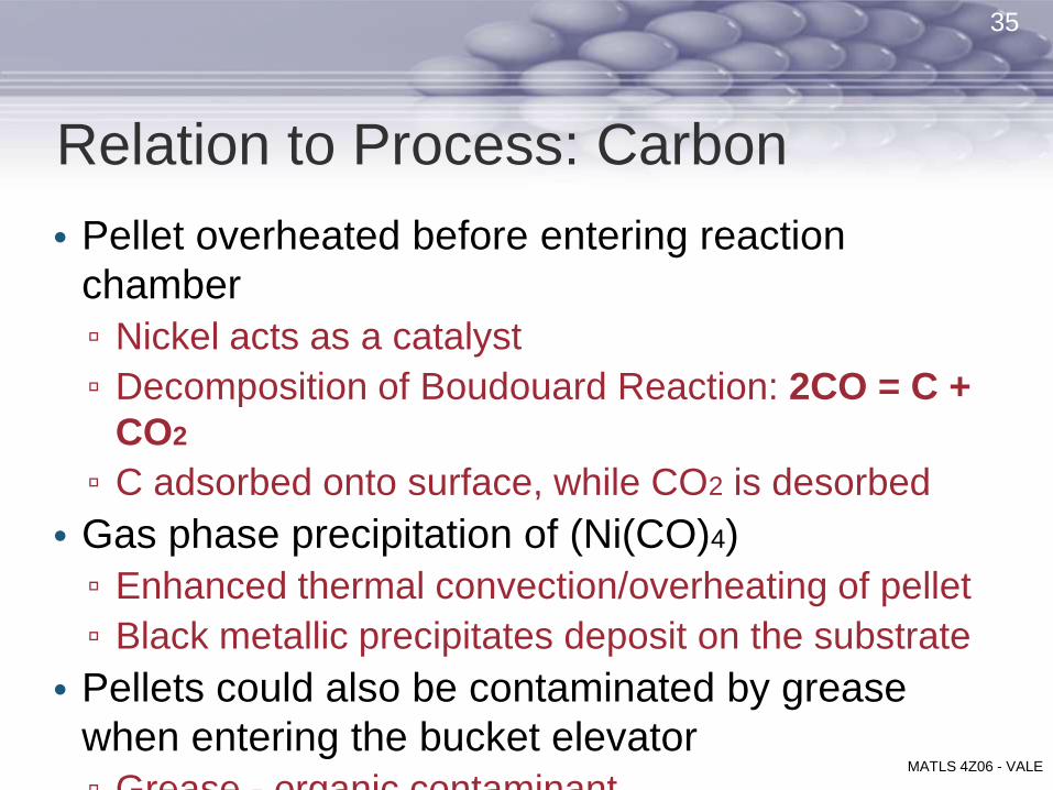
• Pellet overheated before entering reaction
chamber
▫ Nickel acts as a catalyst
▫ Decomposition of Boudouard Reaction: 2CO = C +
CO2
▫ C adsorbed onto surface, while CO2 is desorbed
• Gas phase precipitation of (Ni(CO)4)
▫ Enhanced thermal convection/overheating of pellet
▫ Black metallic precipitates deposit on the substrate
• Pellets could also be contaminated by grease
when entering the bucket elevator
▫ Grease - organic contaminant
Relation to Process: Carbon
35
MATLS 4Z06 - VALE

Sustainability Issues• Nickel carbonyl very toxic compound
▫ Make-vessel purged with inert gas to ensure
no carbonyl gas escapes
▫ Recycling of CO = efficiency
Economic Issues• Pellets used in electroplating market
▫ Broken layer has an effect on uniform
dissolution of pellet
36
MATLS 4Z06 - VALE

Conclusion
• Layer breaks as a result of high content of
impurities
• Future Recommendation:
▫ Use of SAM to detect exact amount of
impurities within layers
▫ Study pellets from the same process/batch to
determine precise process conditions have
effect on pellet formation
37
MATLS 4Z06 - VALE

References
[1] M. D. Head, V. A. Englesakis, B. C. Pearson, and D. H. Wilkinso, "Nickel Refining by the TBRC smelting and pressure carbonyl route," in 105th AIME Annual Meeting, Las Vegas, Nevada, 1976.
[2] "Carbonyl Refining of Impure Nickel Metal," in Extractive Metallurgy of Nickel, Cobalt and Platinum-Group Metals.: Elsevier Ltd., 2011, ch. Chapter 22, pp. 269-280.
[3] C. Chen, "Experimental study of the microstructural evolution of chemical vapour deposited (CVD) nickel upon annealing," University of Toronto, Toronto, Masters Thesis 2011.
[4] M. Skibo and F.A. Greulich, "Characterization of Chemically Vapor Deposited Ni-(0.05-0.20wt%)B Alloys," Thin Solid Films – Preparation and Characterization, vol. volume, (issue number), pp.225-234, January 13 1984.
[5] Valerie Randle. “Electron Backscatter Diffraction (EBSD) of Sectioned Nickel Pellets to reveal core grain boundary structure”. [Vale]
[6] B. Mellor, Surface Coatings for Protection Against Wear, Cambridge, England: WoodheadPublishing Limited, 2006.
[7] P. B. Bansa, “Property Characterization of CVD Nickel,” Toronto, 1998-2001.[8] L. Mond, L. Carl and Q. Friedrich, “Action of Carbon Monoxide on Nickel,” Journal of the
Chemical Society Transactions, vol. 57, no. 0, pp. 749-753, 1890.[9] S. D. Jackson, N. Hussain and S. Munro, “High temperature adsorption of carbon
monoxide and hydrocarbon gases over nickel and platinum catalysts,” Journal of the Chemical Society, Faraday Transactions, vol. 94, pp. 955-961, 1998.
[10] C. V. S. Lim, “Length Scale Effect on the Microstructural Evolution of Cu Layer in a Roll-bonded,” ProQuest LLC, Ann Arbor, MI, 2008.
38
MATLS 4Z06 - VALE

Thank you.
Any questions or comments?
39
MATLS 4Z06 - VALE

Effect of Temperature
• Heat transfer across bed of pellets• Carbonyl gas enters chamber at 70C
(http://books.google.ca/books?id=6aP3te2hGuQC&pg=PA372&lpg=PA372&dq=nickel+carbon+monoxide+in+bucket+elevator&source=bl&ots=wPZIEPR7Zc&sig=IFcrwkDYak0iFkQt6pkcOUrjUL8&hl=en&sa=X&ei=EBNwT4vYNcz5ggel46Rr&ved=0CDkQ6AEwAw#v=onepage&q=nickel%20carbon%20monoxide%20in%20bucket%20elevator&f=false)
• Carbonyl content is max 15wt% to prevent pellet coalescence by high rate of nickel deposition
• Enter preheater at 180C and gets heated to 220 (US decomposer patent)
• Presence of baffle located before rxn chamber to slow down the passage of pellets
• Flow of pellets laminar (patent)• High diffusion rate of S on the 111 plane; S –poisoning of Ni catalyst• CVD diffusion controlled; boundary layer = mass transfer
▫ Inc. Thermal conv removes CO faster from surface = faster reaction
40

![IT331 Network Development Capstone Project [Onsite]thespringergroup.yolasite.com/resources/IT331_Appendix_A.pdf · Network Development Capstone Project Appendix A—Capstone Project](https://img.pdfslide.us/doc/110x75/5aa073e07f8b9a62178e2123/it331-network-development-capstone-project-onsite-development-capstone-project.jpg)