Embed Size (px)
Citation preview
1
GSMGlobal System for
Mobiles Communication
TOPICS
TELECOM BASIS GSM HISTORY GSM CONCEPT AND STRUCTURE IDENTITIES USED IN GSM MOBILITY MANAGEMENT CALL MANAGEMENT
2
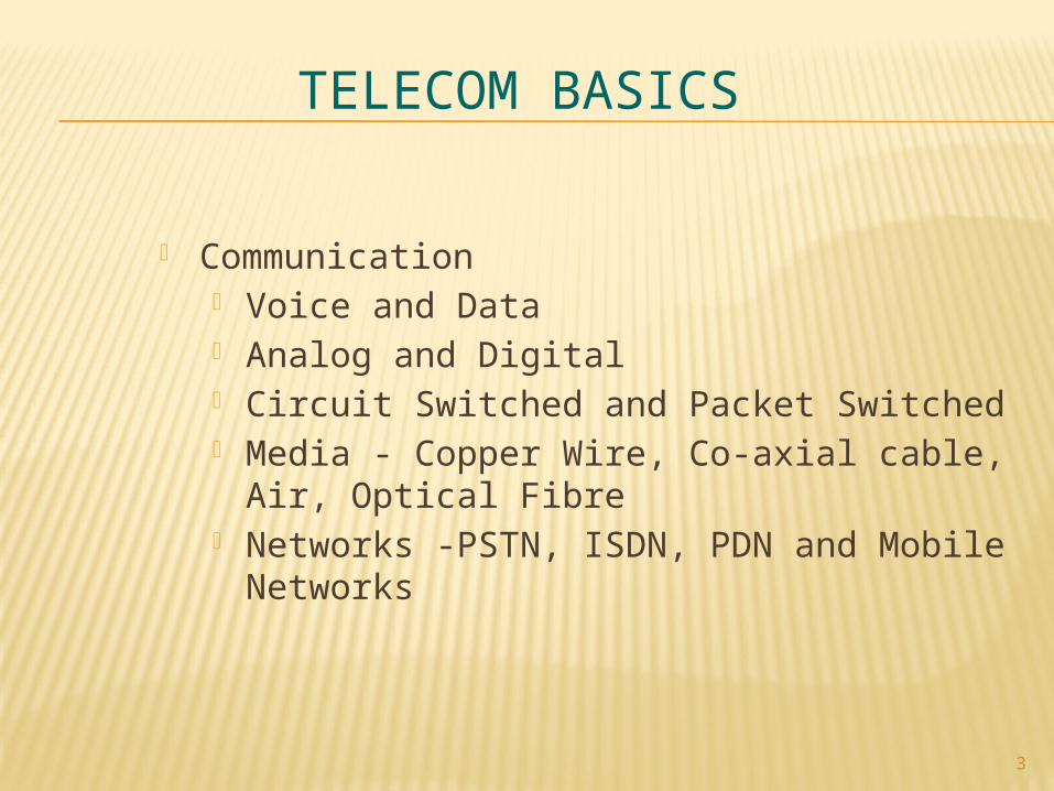
TELECOM BASICS
Communication Voice and Data Analog and Digital Circuit Switched and Packet Switched Media - Copper Wire, Co-axial cable, Air, Optical
Fibre Networks -PSTN, ISDN, PDN and Mobile
Networks
3
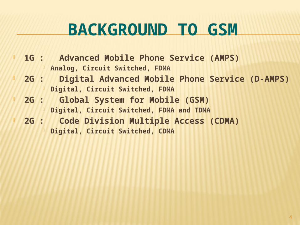
BACKGROUND TO GSM
1G : Advanced Mobile Phone Service (AMPS) Analog, Circuit Switched, FDMA
2G : Digital Advanced Mobile Phone Service (D-AMPS) Digital, Circuit Switched, FDMA
2G : Global System for Mobile (GSM) Digital, Circuit Switched, FDMA and TDMA
2G : Code Division Multiple Access (CDMA) Digital, Circuit Switched, CDMA
4
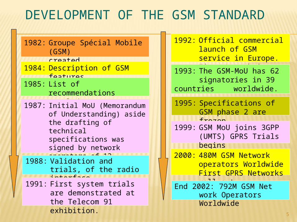
DEVELOPMENT OF THE GSM STANDARD
5
1982: Groupe Spécial Mobile (GSM) created
1984: Description of GSM features
1985: List of recommendations settled
1987: Initial MoU (Memorandum of Understanding) aside the drafting of technical specifications was signed by network operators of 13 countries:
1988: Validation and trials, of the radio interface.
1991: First system trials are demonstrated at the Telecom 91 exhibition.
1992: Official commercial launch of GSM service in Europe. First Launch in Finland1993: The GSM-MoU has 62 signatories in 39
countries worldwide.
1995: Specifications of GSM phase 2 are frozen.
1999: GSM MoU joins 3GPP (UMTS) GPRS Trials begins
2000: 480M GSM Network operators WorldwideFirst GPRS Networks roll out
End 2002: 792M GSM Net work Operators
Worldwide
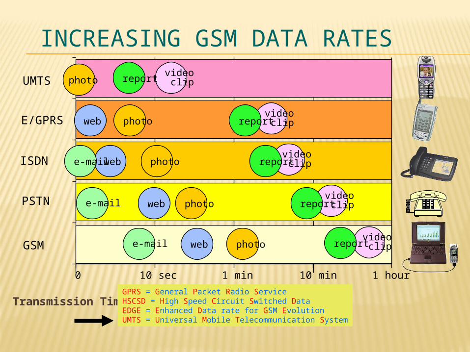
INCREASING GSM DATA RATES
Transmission TimeGPRS = General Packet Radio ServiceHSCSD = High Speed Circuit Switched DataEDGE = Enhanced Data rate for GSM EvolutionUMTS = Universal Mobile Telecommunication System
10 sec 1 min 10 min 1 hour0
UMTS
E/GPRS
ISDN
PSTN
GSM
webe-mail photo
web photoe-mail
web photo
video clipreportphoto
web photoe-mail
video clipreport
video clipreport
video clipreport
video clipreport
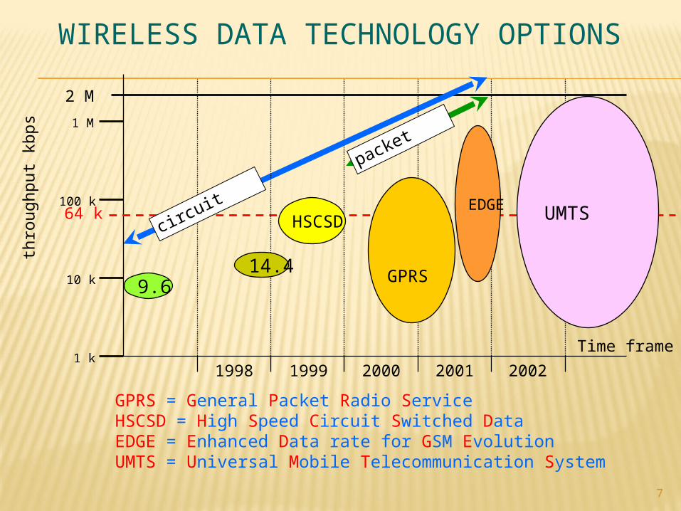
WIRELESS DATA TECHNOLOGY OPTIONS
7
thro
ug
hp
ut
kbp
s
10 k
100 k64 k
1 M
2 M
1 k1998 1999 2000 2001 2002
Time frame
UMTS
GPRS
HSCSD
9.614.4
packet
GPRS = General Packet Radio ServiceHSCSD = High Speed Circuit Switched DataEDGE = Enhanced Data rate for GSM EvolutionUMTS = Universal Mobile Telecommunication System
EDGEcircuit
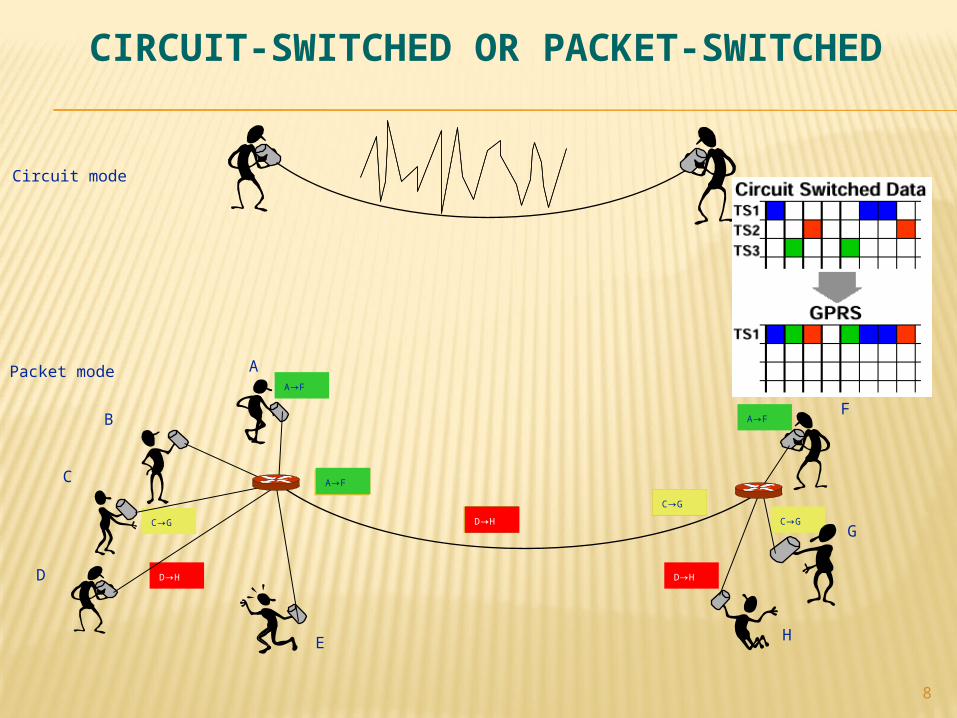
CIRCUIT-SWITCHED OR PACKET-SWITCHED
8
Circuit mode
Packet mode
A→FD→H
C→G
C→G
C→G
C→G
C→G
D→H
D→H
A→FD→H
D→H
A→F
A→F
A→F
A
B
C
D
E
F
G
H
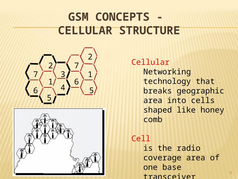
GSM CONCEPTS - CELLULAR STRUCTURE
9
CellularNetworking technology that breaks geographic area into cells shaped like honey comb
Cellis the radio coverage area of one base transceiver station
1
23
45
6
76
72
1
5
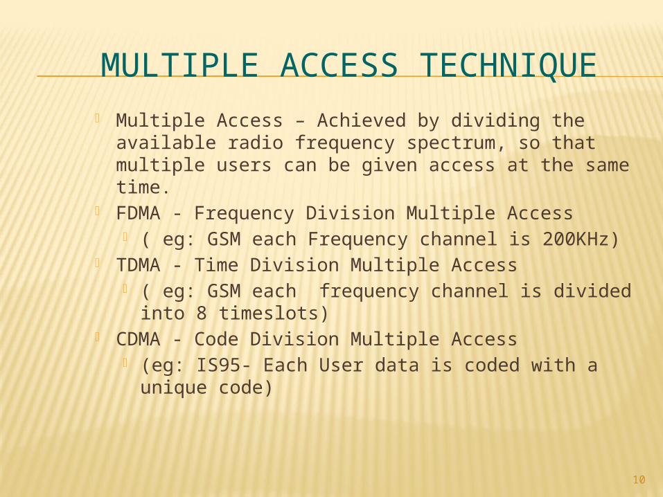
MULTIPLE ACCESS TECHNIQUE
Multiple Access – Achieved by dividing the available radio frequency spectrum, so that multiple users can be given access at the same time.
FDMA - Frequency Division Multiple Access ( eg: GSM each Frequency channel is 200KHz)
TDMA - Time Division Multiple Access ( eg: GSM each frequency channel is divided into 8
timeslots) CDMA - Code Division Multiple Access
(eg: IS95- Each User data is coded with a unique code)
10
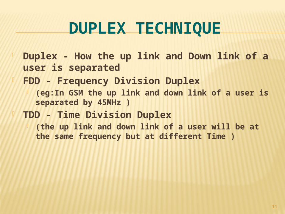
DUPLEX TECHNIQUE
Duplex - How the up link and Down link of a user is separated
FDD - Frequency Division Duplex (eg:In GSM the up link and down link of a user is separated by
45MHz ) TDD - Time Division Duplex
(the up link and down link of a user will be at the same frequency but at different Time )
11
12
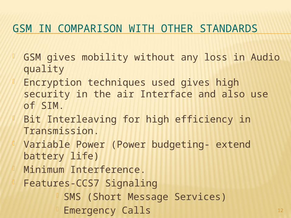
GSM IN COMPARISON WITH OTHER STANDARDS
GSM gives mobility without any loss in Audio quality Encryption techniques used gives high security in the air
Interface and also use of SIM. Bit Interleaving for high efficiency in Transmission. Variable Power (Power budgeting- extend battery life) Minimum Interference. Features-CCS7 Signaling
SMS (Short Message Services) Emergency Calls CELL Broadcast
13
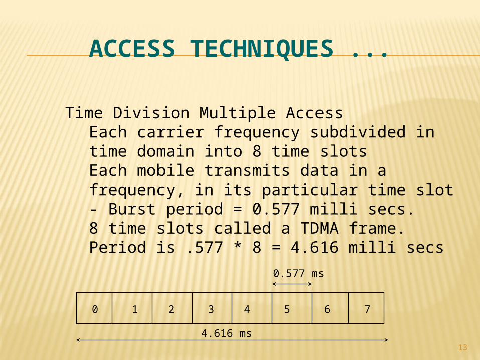
Time Division Multiple AccessEach carrier frequency subdivided in time domain into 8 time slots Each mobile transmits data in a frequency, in its particular time slot - Burst period = 0.577 milli secs.8 time slots called a TDMA frame. Period is .577 * 8 = 4.616 milli secs
0 1 2 3 4 5 6 7
4.616 ms
0.577 ms
ACCESS TECHNIQUES ...
14
AuC
MS
MS
BTS
BTS
BTS
BSC
BSC
MSC
MSC
VLR
VLR
GMSC
HLR
PSTN
EIR
Um
A
A
OMC Server
Um
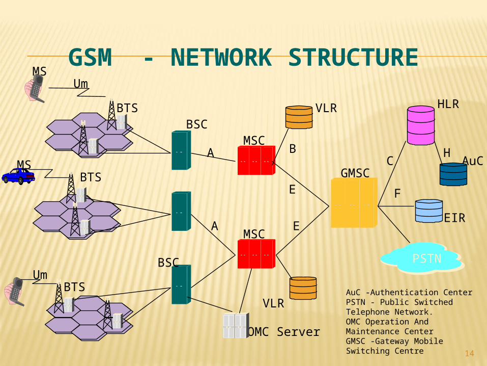
GSM - NETWORK STRUCTURE
B
E
E
C
F
H
AuC -Authentication CenterPSTN - Public Switched Telephone Network.OMC Operation And Maintenance CenterGMSC -Gateway Mobile Switching Centre
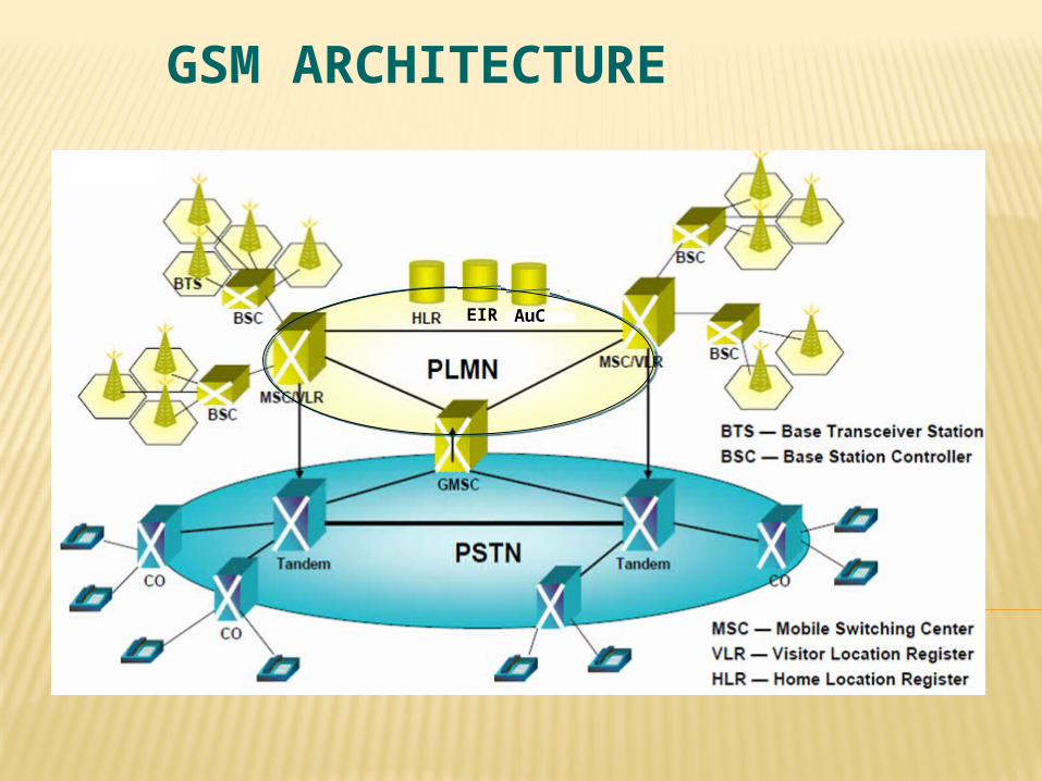
GSM ARCHITECTURE
EIR AuC
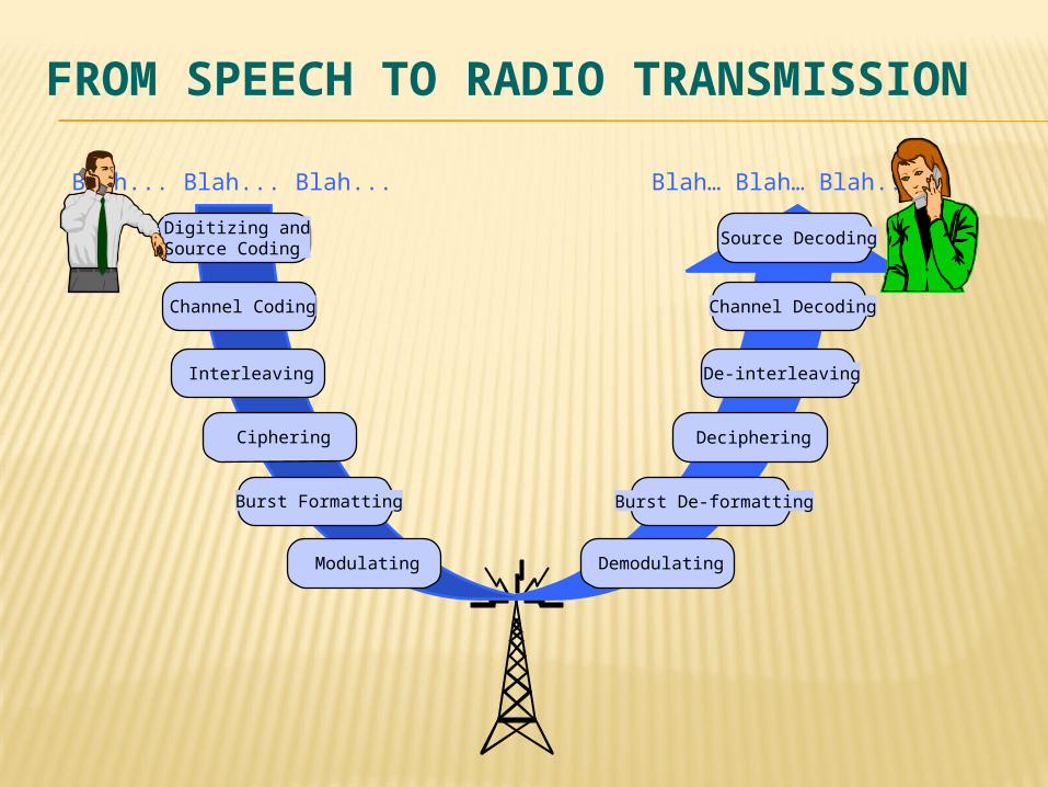
FROM SPEECH TO RADIO TRANSMISSION
Blah… Blah… Blah...Blah... Blah... Blah...
Digitizing andSource Coding
Channel Coding
Interleaving
Ciphering
Burst Formatting
Modulating Demodulating
Burst De-formatting
Deciphering
De-interleaving
Channel Decoding
Source Decoding
17
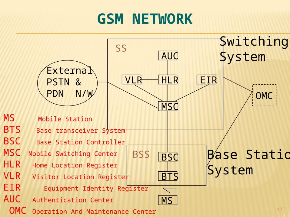
GSM NETWORK
OMC
AUC
HLR
MSC
EIRVLR
BSC
BTS
MS
ExternalPSTN &PDN N/W
SS
BSS
SwitchingSystem
Base StationSystem
MS Mobile Station
BTS Base transceiver System
BSC Base Station Controller
MSC Mobile Switching Center
HLR Home Location Register
VLR Visitor Location Register
EIR Equipment Identity Register
AUC Authentication Center
OMC Operation And Maintenance Center
18
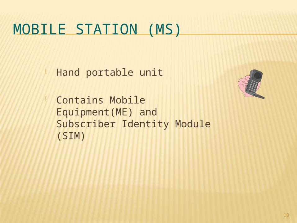
MOBILE STATION (MS)
Hand portable unit
Contains Mobile Equipment(ME) and Subscriber Identity Module (SIM)
19
MOBILE EQUIPMENT(ME)
Frequency and Time Synchronization Voice encoding and transmission Voice encryption/decryption functions Power measurements of adjacent cells Display of short messages International Mobile Equipment Identifier (IMEI)
20
SIM Portable Smart Card with memory (ROM-6KB to 16KB-A3/A8
algorithm, RAM- 128KB TO 256KB, EEPROM- 3KB to 8KB ) Static Information
International Mobile Subscriber Identity(IMSI) Personal Identification Number (PIN) Authentication Key (Ki)
Dynamic Information Temporary Mobile Subscriber Identity(TMSI) Location Area Identity (LAI) Phone memories, billing information Ability to store Short Messages received
21
BASE STATION CONTROLLER (BSC)
Provides all the control functions and physical links between the MSC and BTS
External Interfaces ‘Abis’ interface towards the BTS ‘A’ interface towards the MSC
Monitors and controls several BTSs Management of channels on the radio interface Alarm Handling from the external interfaces Performs inter-cell Handover Switching from ‘Abis’ link to the ‘A’ link Interface to OMC for BSS Management
22
MOBILE SWITCHING CENTER (MSC)
Performs call switching Interface of the cellular network to PSTN Routes calls between PLMN and PSTN Queries HLR when calls come from PSTN to mobile user Inter-BSC Handover Paging Billing
23
HOME LOCATION REGISTER (HLR)
Stores user data of all Subscribers related to the GMSC International Mobile Subscriber Identity(IMSI) Users telephone number (MS ISDN) Subscription information and services VLR address Reference to Authentication center for key (Ki)
Referred when call comes from public land network
24
VISITOR LOCATION REGISTER (VLR)
Database that contains Subscriber parameters and location information for all mobile subscribers currently located in the geographical area controlled by that VLR
Identity of Mobile Subscriber Copy of subscriber data from HLR Generates and allocates a Temporary Mobile
Subscriber Identity(TMSI) Location Area Code Provides necessary data when mobile
originates call
25
AUTHENTICATION CENTER (AUC)
Stores Subscriber authentication data called Ki, a copy of which is also stored in in the SIM card
Generates security related parameters to authorize a subscriber (SRES-Signed RESponse)
Generates unique data pattern called Cipher key (Kc) for user data encryption
Provides triplets - RAND, SRES & Kc, to the HLR on request.
26
EIR (EQUIPMENT IDENTITY REGISTER)
EIR is a database that contains a list of all valid mobile station equipment within the network,
where each mobile station is identified by its International Mobile Equipment Identity(IMEI).
EIR has three databases., White list - For all known,good IMEI’s Black list - For all bad or stolen handsets Grey list - For handsets/IMEI’s that are
on observation
28
GSM PROTOCOLS
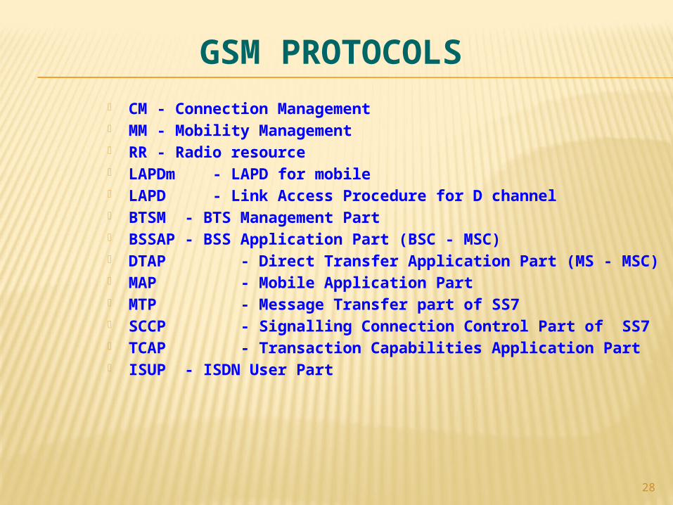
CM - Connection Management MM - Mobility Management RR - Radio resource LAPDm - LAPD for mobile LAPD - Link Access Procedure for D channel BTSM - BTS Management Part BSSAP - BSS Application Part (BSC - MSC) DTAP - Direct Transfer Application Part (MS - MSC) MAP - Mobile Application Part MTP - Message Transfer part of SS7 SCCP - Signalling Connection Control Part of SS7 TCAP - Transaction Capabilities Application Part ISUP - ISDN User Part
29
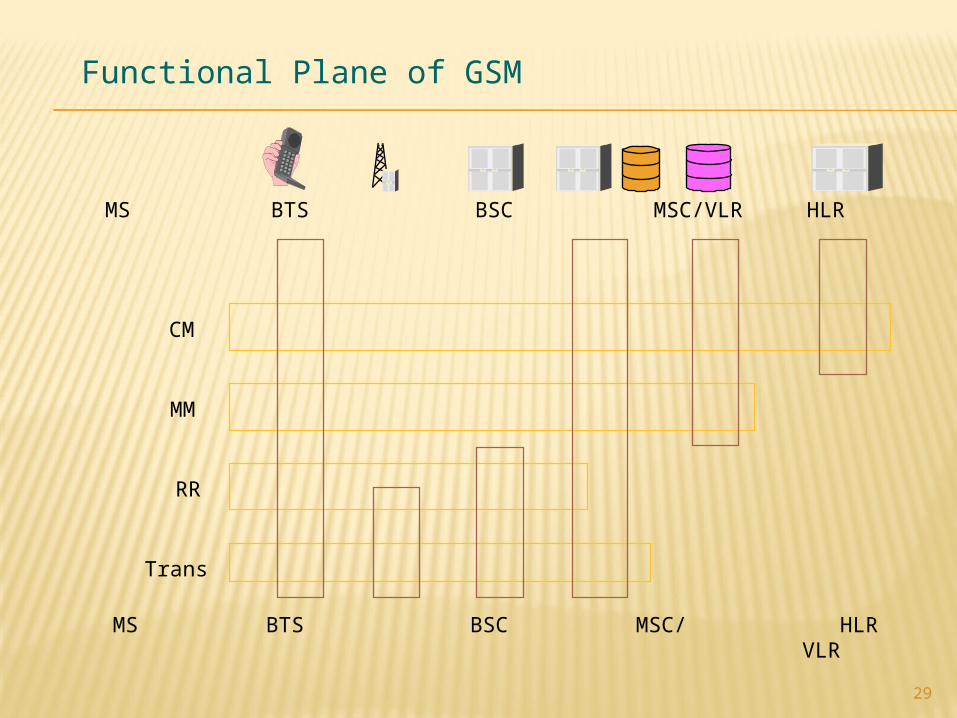
Functional Plane of GSM
MS BTS BSC MSC/ HLR GMSC VLR
MS BTS BSC MSC/VLR HLR GMSC
CM
MM
RR
Trans
30
SUBSCRIBER IDENTITY -MSISDN
The MSISDN is a GSM directory number which uniquely identifies a mobile subscription in the Public Switched Telephone Network (PSTN).
Calls will be routed from the PSTN and other networks based on the Mobile Subscribers’ MSISDN number.
MSISDN= CC + NDC + SN CC= Country Code (91) NDC= National Destination Code(98370) SN= Subscriber Number (12345)
31
INTERNATIONAL MOBILE SUBSCRIBER IDENTITY [IMSI]
Subscriber always identified within the GSM network by the IMSI
This is used for all signaling in the PLMN stored in SIM and HLR/VLR
The IMSI consists of three different parts MCC = Mobile Country Code(3 Digits) MNC = Mobile Network Code(2 Digits) MSIN = Mobile Station Identification Number(Upto 10 digits)
32
TEMPORARY MOBILE SUBSCRIBER IDENTITY [TMSI]
The TMSI is used for the subscriber’s confidentiality. It should be combined with the LAI to uniquely identify a MS. Since the TMSI has only local significance (that is, within the
MSC/VLR area), the structure may be chosen by each administration.
The TMSI should not consist of more than four octets.
33
INTERNATIONAL MOBILE EQUIPMENT IDENTITY [IMEI]
The IMEI is used for equipment identification. An IMEI uniquely identifies a mobile station as a piece or
assembly of equipment. IMEI = TAC + FAC + SNR + sp
TAC= Type Approval Code (6 digits),determined by GSM body FAC= Final Assembly Code (2 digits), identifies
themanufacturer SNR= Serial Number (6 digits), uniquely identifying all
equipment within each TAC and FAC sp = Spare for future use (1 digit)
34
TRAFFIC CHANNELS-TCH
TCH carries the voice data. Two blocks of 57 bits contain voice data in the normal burst. One TCH is allocated for every active call. Full rate traffic channel occupies one physical channel(one
TS on a carrier) and carries voice data at 13kbps Two half rate (6.5kbps) TCHs can share one physical
channel.
35
FRAMES TYPES ON UM INTERFACE TDMA Frame
8 Time slots (Burst Period) Length is 4.62 ms(8 * 0.577ms)
26-TDMA Multiframe 26 TDMA Frames (24 TCH, SACCH, Idle) 120 ms (26 * 4.62ms)
51-TDMA Multiframe 26 TDMA Frames (FCCH, SCH, BCCH, SDCCH, CCCH) 235.6 ms (51 * 4.62ms)
36
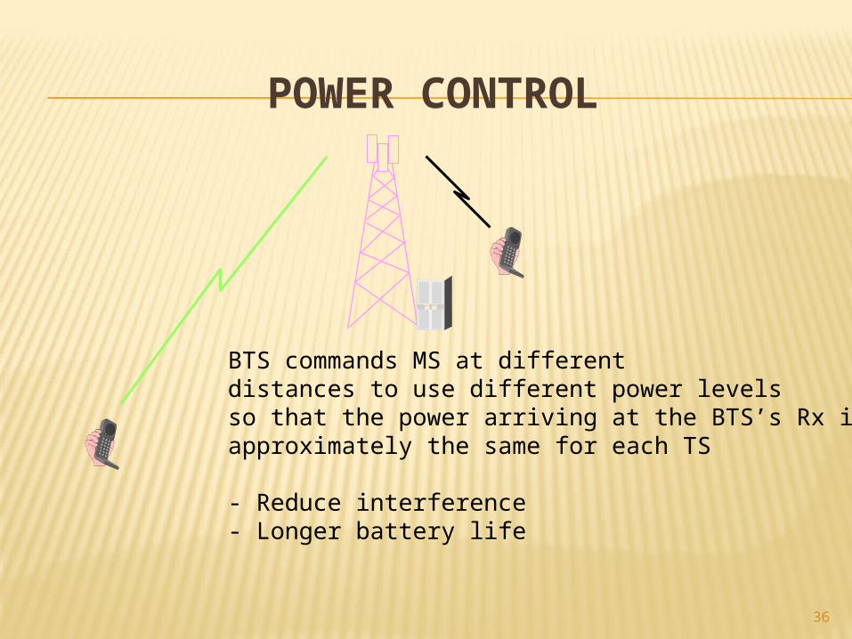
BTS commands MS at differentdistances to use different power levelsso that the power arriving at the BTS’s Rx isapproximately the same for each TS
- Reduce interference- Longer battery life
POWER CONTROL
37
HANDOVER
Means to continue a call even a mobile crosses the border of one cell to anotherProcedure which made the mobile station really roamHandover causes
RxLev (Signal strength , uplink or downlink)RxQual (BER on data)O & M interventionTiming AdvanceTraffic or Load balancing
38
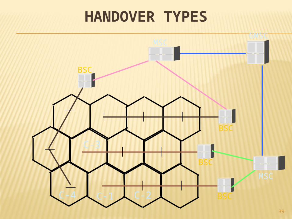
HANDOVER TYPES
Internal Handover (Intra-BSS) Within same base station - intra cell Between different base stations - inter cell
External Handover (Inter-BSS) Within same MSC -intra MSC Between different MSCs - inter-MSC
39
HANDOVER TYPES
BSC
BSC
BSC
BSC
MSC
MSC
GMSC
C-1 C-2
C-3
C-4
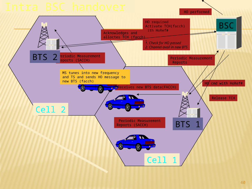
40
Periodic Measurement Reports (SACCH)
Periodic Measurement Reports
HO requiredActivate TCH(facch)with HoRef#
if 1. Check for HO passed2. Channel avail in new BTS
Acknowledges and alloctes TCH (facch)
HO cmd with HoRef#Receives new BTS data(FACCH)
MS tunes into new frequency and TS and sends HO message to new BTS (facch)
Periodic Measurement Reports (SACCH)
HO performed
Release TCH
Cell 1
Cell 2
BSC
BTS 1
BTS 2
Intra BSC handover
41
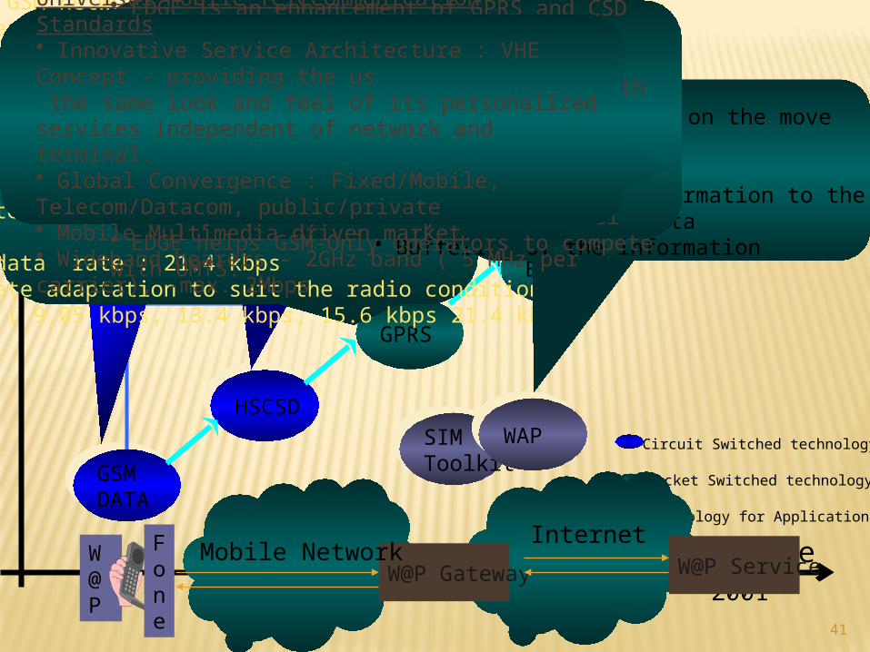
WIRELESS DATA
98 99 2000 2001
GSMDATAGSMDATA
HSCSDHSCSD
GPRSGPRS
EDGEEDGE
UMTSUMTS
SIMToolkitSIMToolkit
WAPWAP
Data Application
Time
Circuit Switched technology
Packet Switched technology
Technology for Applications
SMS Data: 160 -numeric charactersUser Data Rate : 9.6kbpsOne time slot over the air interface
High Speed Circuit Switched DataUser Data Rate:14.5kbpsUse multiple timeslots (max=8), hence max rate = 115.2kbps.Needs a duplexor in MS for simultaneous Tx and Rx
Add-on to GSM network : PCU; Packet Segmentation/re-assembly and scheduling• Radio channel access control and management• Transmission error detection and retransmission.• Power controlSGSN: GPRS mobility• Encryption• Charging GGSN : Interface to the PDN, Internet
Max user data rate : 21.4 kbpsDynamic rate adaptation to suit the radio conditions at that time ( 9.05 kbps, 13.4 kbps, 15.6 kbps 21.4 kbps)
W@P Gateway W@P ServiceW@P
Fone
InternetMobile Network
Surf the Internet while on the move
W@P Gateway :• Adaptation of the information to the mobile• Compression of the data• Buffering of the information
Enhanced Data rate for GSM Evolution• EDGE is an enhancement of GPRS and CSD technologies.• Based on the current GSM technology - same TDMA frame structure, same bandwidth (200 kHz).• Uses 8-PSK modulation instead of GMSK.• Requires good propagation conditions. • Allows upto 48 kbps (EGPRS) and upto 28.8 kbps (ECSD) on every radio channel• EDGE helps GSM-Only operators to compete with UMTS.
Universal Mobile Telecommunication Standards • Innovative Service Architecture : VHE Concept - providing the us the same look and feel of its personalized services independent of network and terminal.• Global Convergence : Fixed/Mobile, Telecom/Datacom, public/private• Mobile Multimedia driven market.• Wideband bearers - 2GHz band ( 5 MHz per carrier), -max. 2Mbps
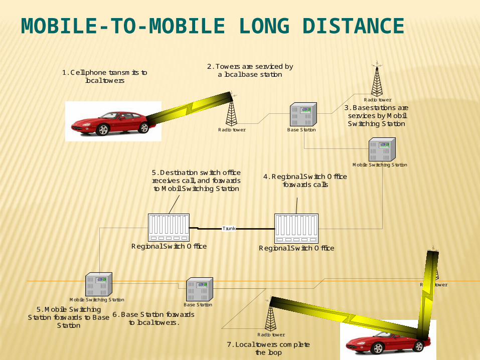
Radio tower
Base Station
Radio tower
Mobile Switching Station
Regional Switch Office Regional Switch Office
Trunk
5. Destination switch officereceives call, and forwardsto Mobil Switching Station
4. Regional Switch Officeforwards calls
Radio tower Base Station
Radio tower
Mobile Switching Station
1. Cell phone transmits tolocal towers
2. Towers are serviced bya local base station
3. Basestations areservices by MobilSwitching Station
5. Mobile SwitchingStation forwards to Base
Station
6. Base Station forwardsto local towers.
7. Local towers completethe loop
MOBILE-TO-MOBILE LONG DISTANCE
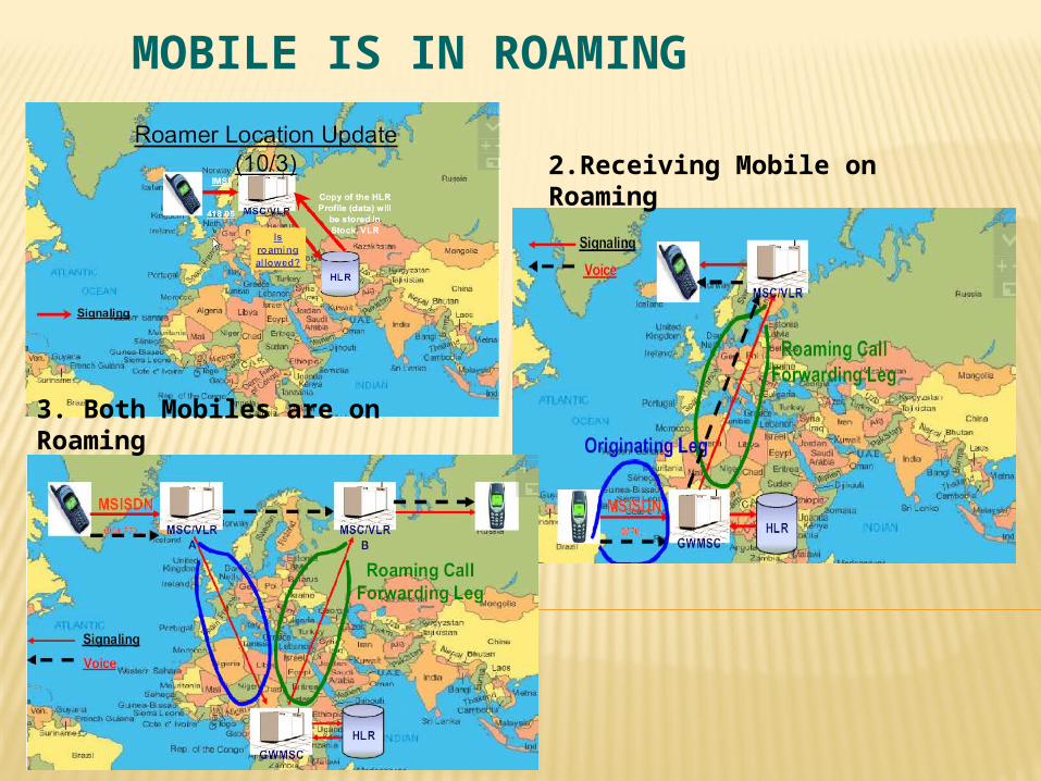
MOBILE IS IN ROAMING
2.Receiving Mobile on Roaming
3. Both Mobiles are on Roaming
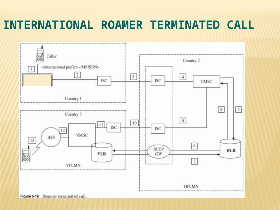
INTERNATIONAL ROAMER TERMINATED CALL
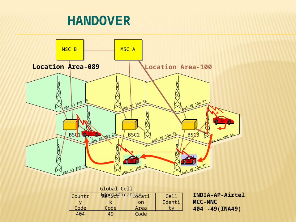
Location AreaCode
Global Cell Identification
CountryCode404
NetworkCode
49
CellIdentity
BSC3BSC2BSC1
MSC B MSC A
404 49 100 53
404 49 100 54
404 49 100 55
404 49 100 51
404 49 100 52
404 49 089 20
404 49 089 21
404 49 089 22
404 49 100 50
Location Area-100Location Area-089
INDIA-AP-AirtelMCC-MNC404 -49(INA49)
HANDOVER

46


![Training Gsm Basic[1]](https://img.pdfslide.us/doc/110x75/577ce7591a28abf10394ee20/training-gsm-basic1.jpg)