Embed Size (px)
Citation preview
TestingAnalogue Electronics
Oscilloscope
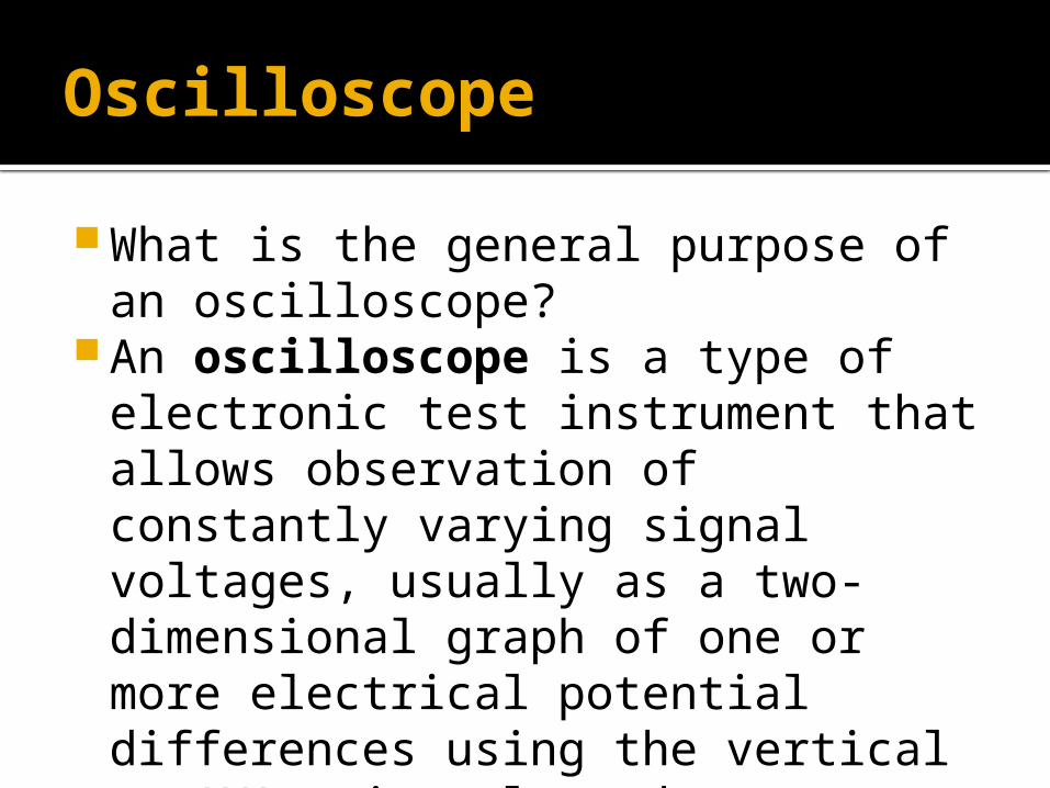
What is the general purpose of an oscilloscope?
An oscilloscope is a type of electronic test instrument that allows observation of constantly varying signal voltages, usually as a two-dimensional graph of one or more electrical potential differences using the vertical or 'Y' axis, plotted as a function of time on the ‘X’ axis.
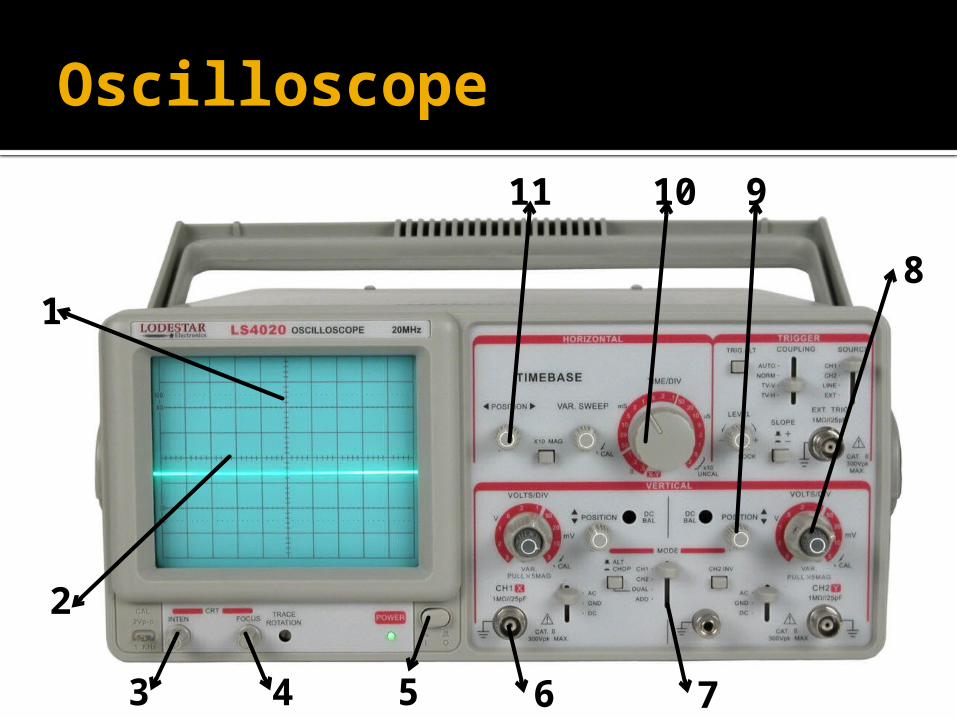
Oscilloscope
5
2
3 4
1
6 7
8
91011
Oscilloscope
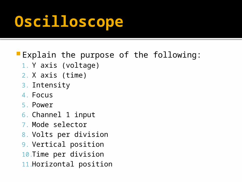
Explain the purpose of the following:1. Y axis (voltage)2. X axis (time)3. Intensity4. Focus5. Power6. Channel 1 input7. Mode selector8. Volts per division9. Vertical position10. Time per division11. Horizontal position
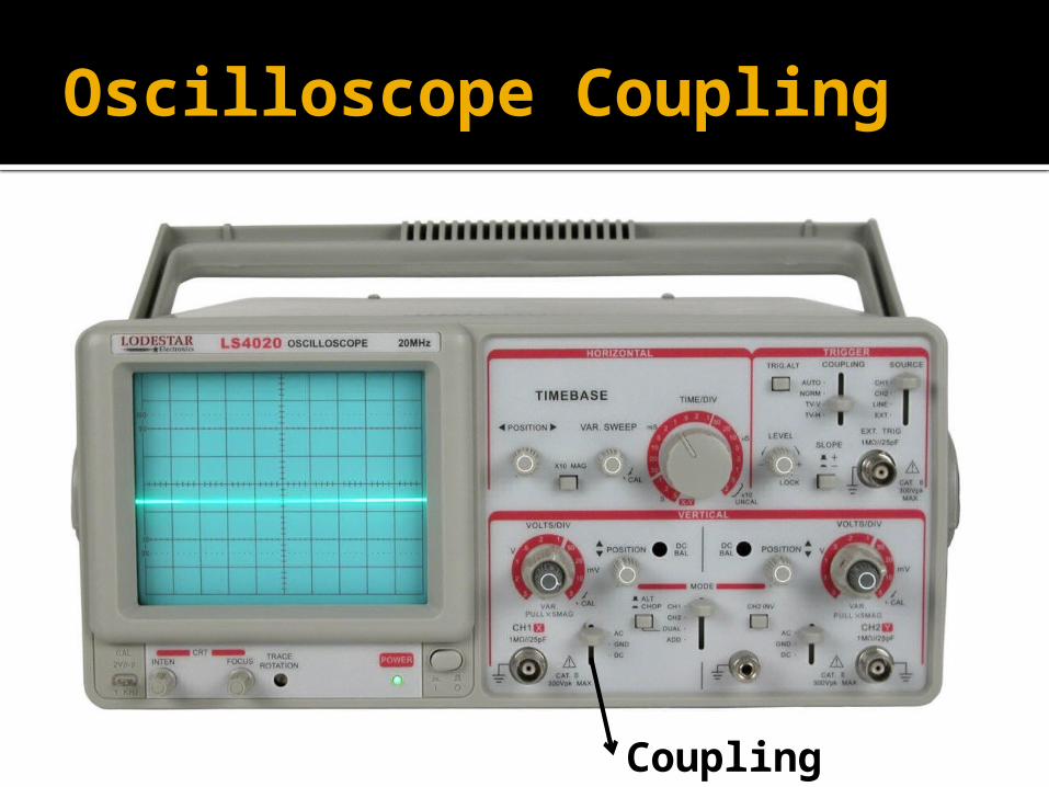
Oscilloscope Coupling
Coupling
Oscilloscope Coupling
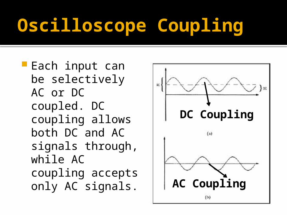
Each input can be selectively AC or DC coupled. DC coupling allows both DC and AC signals through, while AC coupling accepts only AC signals.
DC Coupling
AC Coupling
Triggering
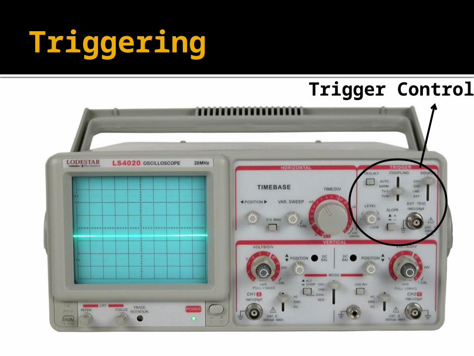
Trigger Controls
Triggering
To display events with unchanging or slowly (visibly) changing waveforms modern oscilloscopes have triggered sweeps.
A triggered sweep starts at a selected point on the signal, providing a stable display. In this way, triggering allows the display of periodic signals such as sine waves and square waves, as well as nonperiodic signals such as single pulses, or pulses that don't recur at a fixed rate.
Triggering
Investigate the purpose of the following trigger controls:1. Slope2. Trig Alt3. Level4. Coupling 5. Source
Signal Generator
52
3 4
1
67 8
9
10
Signal Generator
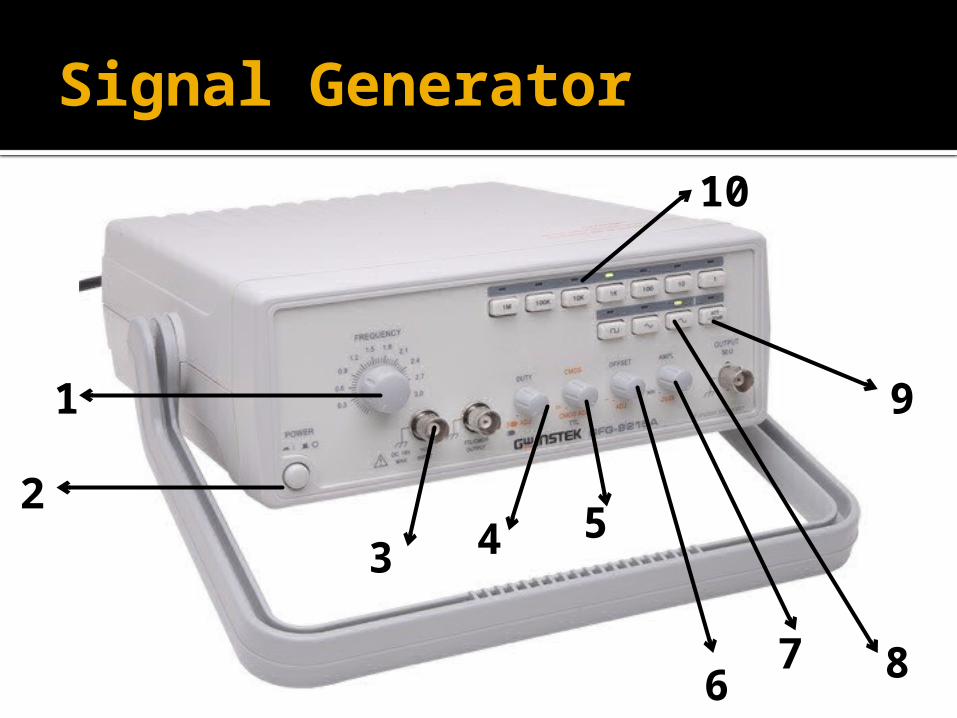
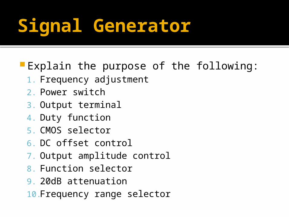
Explain the purpose of the following:1. Frequency adjustment2. Power switch3. Output terminal4. Duty function5. CMOS selector6. DC offset control7. Output amplitude control8. Function selector9. 20dB attenuation10.Frequency range selector
Multimeter
5
2
3
1
8
67
4
91011
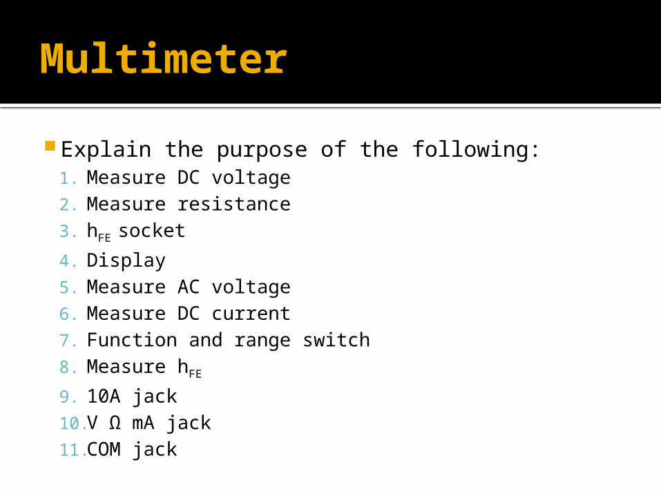
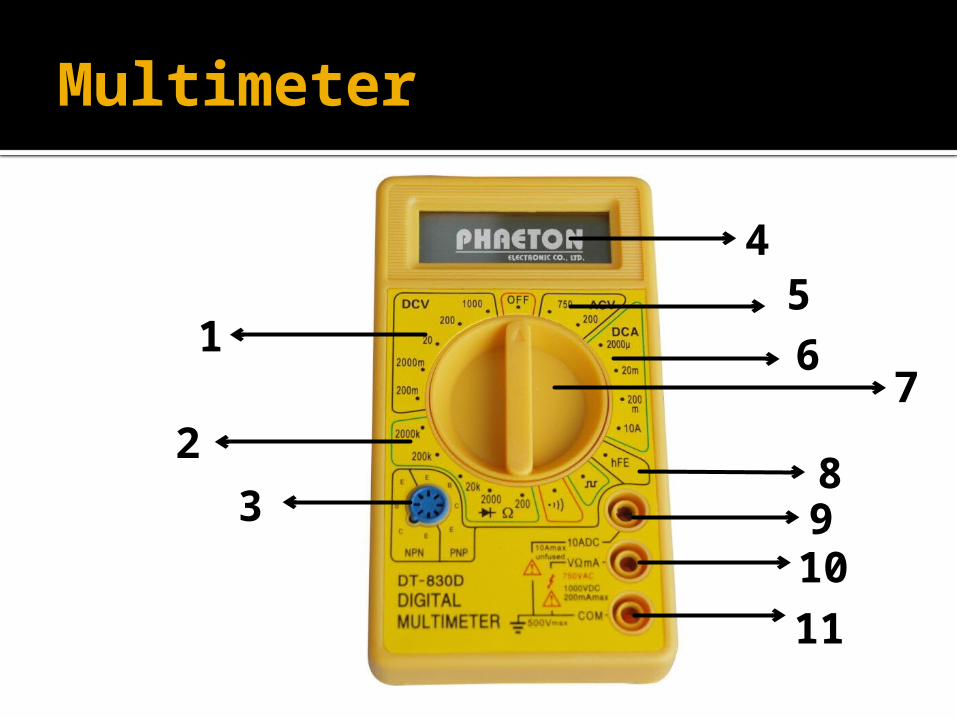
Multimeter
Explain the purpose of the following:1. Measure DC voltage2. Measure resistance3. hFE socket
4. Display5. Measure AC voltage6. Measure DC current7. Function and range switch8. Measure hFE
9. 10A jack10. V Ω mA jack 11. COM jack
Accuracy
The accuracy of a measurement system is the degree of closeness of measurements of a quantity to that quantity's actual (true) value.
For example standard portable digital multi-meters are specified to have an accuracy of typically 0.5% on the DC voltage ranges.
Test equipment tends to drift out of calibration over time, and the specified accuracy cannot be relied upon indefinitely.
Bandwidth
Bandwidth is the difference between the upper and lower frequencies in a contiguous set of frequencies. It is typically measured in hertz.
The bandwidth of a piece of test equipment is the range of frequencies over which the equipment can make accurate measurements.
Resolution
Resolution of a meter, which is defined as the lowest voltage, current or resistance change that can change the observed reading.