Embed Size (px)
Citation preview
MANUAL OF CONTRACT DOCUMENTS FOR HIGHWAY WORKSVOLUME 2 NOTES FOR GUIDANCE ON THE SPECIFICATION FOR HIGHWAY WORKS
SERIES NG 600EARTHWORKS
Contents
Clause Title Page
NG 600 Introduction 2NG 601 Classification, Definition and Uses of
Earthworks Materials and Table 6/1:Acceptable Earthworks Materials:Classification and CompactionRequirements 3
NG 602 General Requirements 5NG 603 Forming of Cuttings and Cutting Slopes 5NG 604 Excavation for Foundations 5NG 605 Special Requirements for Class 3
Material 5NG 606 Watercourses 5NG 607 Explosives and Blasting for Excavation 6NG 608 Construction of Fills 6NG 609 Geotextiles Used to Separate Earthworks
Materials 6NG 610 Fill to Structures 6NG 611 Fill Above Structural Concrete
Foundations 7NG 612 Compaction of Fills 7NG 613 Sub-formation and Capping 7NG 614 Cement Stabilisation to Form Capping 8NG 615 Lime Stabilisation to Form Capping 8NG 616 Preparation and Surface Treatment of
Formation 8NG 617 Use of Sub-formation or Formation by
Construction Plant 8NG 618 (05/01) Topsoiling 8NG 619 Earthwork Environmental Bunds 8NG 620 Landscape Areas 8NG 621 Strengthened Embankments 9NG 622 Earthworks for Reinforced Soil and
Anchored Earth Structures 9NG 623 Earthworks for Corrugated Steel Buried
Structures 9NG 624 Ground Anchorages 9NG 625 Crib Walling 9NG 626 Gabions 9NG 628 Disused Mine Workings 9NG 629 Instrumentation and Monitoring 10NG 630 Ground Improvement 10NG 631 Earthworks Materials Tests 12#NG 632 Determination of Moisture Condition
Value (MCV) of Earthworks Materials 13
Clause Title Page
NG 633 Determination of Undrained ShearStrength of Remoulded CohesiveMaterial 13
NG 636 Determination of Effective Angle ofInternal Friction (ϕ/) and EffectiveCohesion (c/) of Earthworks Materials 13
NG 637 Determination of Resistivity (rs) toAssess Corrosivity of Soil, Rock orEarthworks Materials 13
NG 638 Determination of Redox Potential (Eh) to Assess Corrosivity of EarthworksMaterials for Reinforced Soil andAnchored Earth Structures 13
NG 639 Determination of Coefficient of Frictionand Adhesion between Fill andReinforcing Elements or AnchorElements for Reinforced Soil andAnchored Earth Structures 14
NG 640 Determination of Permeability ofEarthworks Materials 14
NG 642 Determination of the Constrained SoilModulus (M*) of Earthworks Materials 14
NG 644 (11/03) Determination of sulfate content 14NG Sample Appendices A1
NATIONAL ALTERATIONS OF THEOVERSEEING ORGANISATIONS OFSCOTLAND, WALES AND NORTHERNIRELAND
Clause Title Page
ScotlandNG 601SE (11/05) Classification, Definitions and
Uses of Earthworks Materials S1NG 632SE (05/01) Determination of Moisture
Condition Value (MCV) of EarthworksMaterials S1
# denotes a Clause or Sample Appendix which has a substitute NationalClause or Sample Appendix for one or more of the OverseeingOrganisations of Scotland, Wales or Northern Ireland.
1Amendment - November 2005
EARTHWORKS
2
NG 600 Introduction
1 The Notes for Guidance on this Series are intendedto assist in the preparation of the Contract. The designof the earthworks and selection of limits for soilproperties for their construction will follow the groundinvestigation. Advice on these and other matters isavailable from the Overseeing Organisation and theDesign Manual for Roads and Bridges (DMRB).Experience in the construction of road schemes hasshown that certain materials may be utilised as‘acceptable’ materials although processing, whereappropriate, will be necessary to render unacceptablematerials ‘acceptable’. Appendix 6/1 should describethe requirement for processing of unacceptable materialwhere this has been identified as appropriate. Unlessthere are specific reasons, the means of processingshould be left to the Contractor. The aim should be tominimise the import of materials both for economic andenvironmental reasons and to allow use in fill areasthose materials likely to arise in the cuttings as far asthe earthworks design permits. However, since theContractor, for economic reasons, should normally beleft the choice of using Site-arising or importedmaterials, the Contract should not normally indicatefrom where on Site materials are to be obtained for thevarious zones of fill (but see also 6(ii) below). Certainselected fills will normally have to be imported.
2 The term ‘rock’ is used in the Specification todescribe a constituent of certain selected fills havingdurability and strength requirements and also todescribe material in cutting faces and formationsrequiring special methods of trimming or regulation.
3 (11/04) Particular requirements, not specificallystated in the SHW, for the Class of fill materials to beused or permitted, or for work to be undertaken shouldbe included in Appendices 6/1 to 6/15. AdditionalAppendices may be used if necessary (see NG 000).
4 It is necessary to show the full extent of formationand where there is capping, the sub-formation. Mostroad configurations will be catered for by theappropriate cross-section and edge detail drawingscontained in the HCD. These drawings should normallybe used without modification and incorporated in theContract by reference (in Appendix 0/4). In cases wherethey do not cover the work involved, Contract-specificdrawings may be necessary which should be discussedwith the Overseeing Organisation.
5 Appendix 6/1 should list only the properties neededto meet design requirements, omitting those which areunnecessary, eg. either mc or MCV, not both.
6 (05/04) Tenderers should be given the fullestavailable information about the materials to beexcavated as required in Advice Note SA9(MCHW 5.3.2). The following should be included, asappropriate:
(i) any strata or deposits designated as HardMaterial;
(ii) the in situ material properties, related as faras possible to the general materialdescription and the properties used foracceptability in Table 6/1, taken from theborehole logs, which may be re-plotted onthe drawings of the long-sections of cuttingsand below embankments where excavationwill be required;
(iii) the total net volume of each cut (neglectingbulking or shrinkage) including:(a) estimated net volume of Class 5A
material to be removed;(b) estimated net volume of acceptable
material;(c) estimated net volume of unacceptable
material above and below formationlevel including the volume to beprocessed to render it acceptable;
(d) the Class and estimated net volume offill to replace any excavation requiredbelow formation level;
(iv) the total net volume of fill in each fill area(neglecting bulking or shrinkage) including:(a) estimated net volume of topsoil to be
removed, if any;(b) estimated net volume of unacceptable
material below existing ground level tobe removed including the volume to beprocessed to render it acceptable;
(c) the Class and estimated net volume offill required above and below existingground level;
(d) the Class, location and estimated netvolume of capping material required orstabilisation of subgrade to formcapping.
Volume 2Notes for Guidance on the Specifications for Highway Works
Series NG 600Earthworks
Amendment - November 2004
3
NG 601 Classification, Definition and Uses ofEarthworks Materials and Table 6/1:Acceptable Earthworks Materials:Classification and Compaction Requirements
1 The key to the use of materials both arising on Siteand imported lies in Table 6/1. These materials havebeen classified into 9 principal Classes and sub-dividedfor compaction purposes or because of particularproperties or applications.
2 Classes 1 and 2, general fills, comprise the greaterpart of the materials normally encountered and whichare satisfactory as fill in most embankmentconstruction. They incorporate chalk except when it islikely to be degraded by normal construction plantwhen it is designated in Appendix 6/1 as Class 3general fill.
3 Classes 4 and 5 are for landscaping and topsoilingrespectively.
4 Classes 6 to 9 selected fills all have a special role.
5 Many schemes will use only a few of the Classes inTable 6/1 and it will be unusual for every Class ofmaterial to be used on an individual scheme.
6 (11/04) Further sub-division of the Classes inTable 6/1 may be appropriate eg. 2A into 2A1 and 2A2in order to obtain the better use of materials by zoning.This system is also applicable for Class U1B materialthat has been processed to meet the requirements of aparticular Class, eg., for 2A this would be 2A1 foracceptable material and U1A that had been processedand 2A2 for U1B that had been processed. Theadditional requirements for 2A2 in terms of limitingvalues of contaminants and the methods of testingwould be set out in 2A2.
7 Appendix 6/1 should include the relevant limits ofacceptability for fill materials referred to in Table 6/1.
8 (11/04) The definition of contaminated materialsClass U1B is based on the concept of risk assessmentand is in accordance with the definition ofcontaminated land in Sections 78A(2), 78A(5) and78A(6) of the Environmental Protection Act 1990 PartIIA (for Northern Ireland it is the Waste andContaminated Land (Northern Ireland) Order 1997) andassociated statutory guidance.
Where contaminated materials have levels ofcontamination below the limiting values in sub-Clause601.2(ii)(a), they remain acceptable materials availablefor classification in accordance with Clauses 601 and602 and Table 6/1.
9 (11/04) A site specific risk assessment should beundertaken for each earthwork section, as the degree ofexposure to living organisms or the hydro-geological
conditions can vary significantly within a scheme,leading to different limiting values in different sections.However, appropriate generic guideline values, whichare based on a risk assessment model, may be used asdefault values. For human health, the series of SoilGuideline Values published by DEFRA and theEnvironment Agency may provide suitable defaultvalues.
10 (11/04) For general fills, the limiting values for harmto human health should normally be based on the‘commercial/industrial’ end use category of guidelinevalues, as there is a very low risk of exposure to thepublic from any contaminants in the fill. Forlandscaping fills, considerations of phytotoxicity willbe important. Where slopes are to be returned toagricultural use, the limiting values should be based onthe ‘allotments’ end use. The appropriate categoryshould be decided for each section or sub-section of thescheme.
11 (11/04) Details of the limiting values adopted andexplanations of their derivations should be given inAppendix 6/14 and Appendix 6/15.
12 (11/04) Materials, which would be classified asClass U1B because of contamination using genericguideline values, may be rendered acceptable byremedial techniques such as treatment withcementitious agents such as cement, lime or pulverized-fuel ash. The contaminant levels are not changed by theremedial treatment, and remain above the genericguideline values, but their ability to migrate is reduced.A site specific risk assessment must be carried out todemonstrate whether the risk to human health andliving organisms, and of pollution of controlled waters,is acceptable before the remediated materials can bere-classified as acceptable fill materials.
13 (11/04) The limiting values in sub-Clauses # 601.14and # 601.15 have been chosen to ensure that problemsdo not occur due to oxidation of reduced sulfurcompounds such as pyrite. However, the limiting valuesonly take account of the total amount of sulfur in eachform, and do not allow consideration of factors such asgrain size, mineralogy and access to air and water thataffect the actual amount of oxidation that will takeplace in any given situation. As a result, the limitingvalues for oxidisable sulfides (OS) and total potentialsulfate (TPS) are conservative, and may excludematerials that have been shown to perform satisfactorilyas structural backfills. Examples of situations wherematerials may exceed the limiting values for structuralbackfills but still be acceptable include the following:
• Pyrite present as large cubic crystals visibleto the naked eye. This will give high valuesof TPS and OS, but the rate of oxidation will
Amendmenrt - November 2004
Volume 2Notes for Guidance on the Specifications for Highway Works
Series NG 600Earthworks
4
be very slow because of the low specificsurface area of the pyrite crystals (eg sampleTR8, Plate 8.3 of TRL Report 447).
• Unreactive sulfates such as barytes presentas vein material or as a cement. This willgive high values of TPS and OS, because theunreactive sulfate will be detected by thetotal sulfur (TS) test but not by the acid-soluble sulfate (AS) test (eg sample TR28 ofTRL Report 447). However, such sampleswould give low values of total reduced sulfur(TRS). If OS is calculated directly from TRSfor these materials, a more accurate valuewill be obtained.
Where this occurs, enquiries should be made as towhether there is any history of corrosion problems withthe material. A programme of detailed testing should becarried out on the material, using the new test methods,to establish its chemistry and mineralogy and ascertainmore clearly its potential to cause corrosion.
Mineralogical methods may include petrographicdescription using thin sections, X-ray diffraction orScanning Electron Microscopy (SEM). If pyrite ispresent in framboidal form (Plates 8.1 and 8.2, sampleTR11D of TRL Report 447), the material should beclassified as unacceptable as structural backfill, becauseof the known tendency of this form of pyrite to oxidiserapidly in engineering situations.
The use of the material may be permitted as structuralbackfill if it can be established to the satisfaction of theOverseeing Organisation that:
• the material has been used in the past asstructural backfill without leading toproblems with sulfur compounds; and
• the reason why the material will not cause aproblem is known, based on anunderstanding of its chemistry andmineralogy.
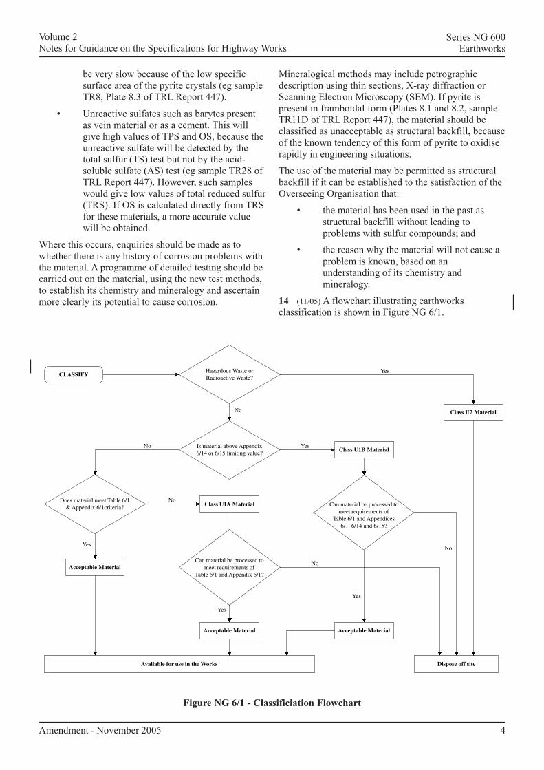
14 (11/05) A flowchart illustrating earthworksclassification is shown in Figure NG 6/1.
Amendment - November 2005
Volume 2Notes for Guidance on the Specifications for Highway Works
Series NG 600Earthworks
Figure NG 6/1 - Classificiation Flowchart
Hazardous Waste orRadioactive Waste?
Is material above Appendix6/14 or 6/15 limiting value?
Does material meet Table 6/1& Appendix 6/1criteria?
Can material be processed tomeet requirements of
Table 6/1 and Appendix 6/1?
Class U1A Material
Acceptable Material
Can material be processed tomeet requirements of
Table 6/1 and Appendices6/1, 6/14 and 6/15?
Available for use in the Works
Class U2 Material
Dispose off site
Yes
Yes
Yes
Yes
Yes
No
No
No
No
No
Acceptable Material
Acceptable Material
CLASSIFY
Class U1B Material
Volume 2Notes for Guidance on the Specifications for Highway Works
Series NG 600Earthworks
5
NG 602 General Requirements
1 Special requirements for determining acceptability,eg. who classifies and where, and whether trial pittingis required, should be stated in Appendix 6/1 (see alsoNG 631).
2 All topsoil above cuttings and below embankmentsshould normally be stripped for re-use with the depthsof excavation given in Appendix 6/8 verified whenstripping. There is frequently less topsoil in woodedareas than expected and this should be recognised whenestimating volumes of topsoil. In soft or marshy areasdisturbance of the crust of topsoil and vegetation maybe unwarranted and such topsoil should be shown onthe Drawings to be left in place and details given inAppendix 6/8. The Overseeing Organisation should beconsulted concerning requirements for surplus topsoil,which should be stored whenever practicable ratherthan disposed of by the Contractor. Storage areas shouldbe shown on the Drawings and details given inAppendix 6/8.
3 The Drawings should indicate where battering ofexcavations for foundations and trenches is permittedand details should be given in Appendix 6/3. It shouldnot be unnecessarily restricted; in some instances itmight be preferable so as to avoid leaving a wedge ofmaterial loosened by excavation. Where battering ispermitted, the requirements for benching prior tobackfilling and compaction should be shown on theDrawings and details given in Appendix 6/3.
4 Where groundwater is to be lowered as a designrequirement, or to make wet unacceptable material intoacceptable material where a shortfall in earthworksvolumes is likely, the location and extent of suchoperations should be shown on the Drawings. Theseshould be cross-referenced in Appendix 6/1.
NG 603 Forming of Cuttings and CuttingSlopes
1 The Drawings should show all changes in cross-section for cuttings and any requirements for limitingthe extent of undercutting of slopes and toes of cuttings,making use of Appendix 6/3 as necessary.
2 Requirements for pre-split blasting, a technique forminimising overbreak and instability, should be statedin Appendix 6/3 for any substantial rock cuttings, whereblasting will be permitted (See NG 607). Requirementsfor exposed cutting faces should be described inAppendix 6/3. Advice on specification requirements forpre-split blasting can be obtained from TRRL reportLR 1094.
NG 604 Excavation for Foundations
1 (11/03) The lines and levels of foundationexcavations should be shown on the Drawings togetherwith any blinding concrete, and its reference, toClause 2602.
2 The Drawings should indicate where therequirement in Clause 602 for not battering excavationsfor foundations can be relaxed and details should begiven in Appendix 6/3 (see NG 602).
NG 605 Special Requirements for Class 3Material
1 Class 3 material caters for chalk in cuttingscomposed mainly of chalk of a type that if left tonormal earthmoving methods would be degraded,causing problems when used as general fill.
2 (11/05) Class 3 will only apply if material is sodesignated in Appendix 6/1, otherwise chalk for generalfill is dealt with as a Class 1A or 1C material. Thespecial requirements for Class 3 material need onlyapply to materials comprising the wetter and less denseChalk Groups C and D.
3 (11/05) Class 3 should be designated utilising theground investigation results and Advice Note HA 44(DMRB 4.1.1). Where most of the material in a cuttingmeets Chalk Groups C and D of that Advice Note thewhole cutting should be designated as Class 3. ThusClass 3 may be a mixture of Chalk Groups A to D orindeed, in small quantities, of harder chalks outside thatclassification. Class 3 can include small amounts ofmaterials other than chalk unable to be separated duringexcavation e.g. flints and head. Further advice on thesematters is available from the Overseeing Organisationand the DMRB (see DMRB 4.1.1).
4 (11/03) The period to be stated in Appendix 6/4when earthworks involving Class 3 material should notbe undertaken should be determined by reference torecords of precipitation and air temperatures for thearea concerned over previous years and other relevantfactors.
NG 606 Watercourses
1 Cross-sections for all work in connection withexisting or new watercourses (which includes all ditchwork) should show the extent of all treatment and otherrequirements. See NG Sample Appendix 6/3.
Amendment - November 2005
Volume 2Notes for Guidance on the Specifications for Highway Works
Series NG 600Earthworks
6
NG 607 Explosives and Blasting forExcavation
1 Blasting needs should be considered in relation tothe likely disturbance to the environment and remainingmaterial beyond the cutting face. Where blasting islikely to lead to savings in excavation costs,pre-construction consultation with all who may beaffected is a pre-requisite to permitting blasting inAppendix 6/3. Further guidance will be found,including benefits of pre-contract blasting trials duringground investigations, in TRRL report RR 53.
NG 608 Construction of Fills
1 The Drawings should show locations and particularrequirements for selected fills and general fills inspecific zones including any additional sub-divisions ofClasses in Table 6/1.
2 The Drawings should also show how, wherepermitted, embankments may be initially constructedother than to their full width and to steeper batterslopes. These should be cross-referenced inAppendix 6/3.
3 Staged construction and any surcharging ofembankments and benching should also be shown, withrequirements for any instrumentation in Appendix 6/12.
4 The Drawings should show each change in cross-section of fills.
NG 609 Geotextiles Used to SeparateEarthworks Materials
1 This Clause includes minimum properties forgeotextiles used to separate earthworks materials exceptfor durability where tests have yet to be developed to anacceptable standard. Evidence of longevity is, however,required from the Contractor.
2 The minimum life stated in Appendix 6/5 shouldrelate to the main function of the geotextile. Forexample, if used beneath an embankment it shouldexceed the time for primary consolidation of theunderlying soil. Rate of sampling should be given inAppendix 6/5 together with any other requirements.
3 The tests in this Clause may be used for specifyinggeotextiles for other purposes, using appropriate valuesof properties, by means of a different Appendix, eg. ifused in strengthened embankments to Clause 621,Appendix 6/9 should be used. The requirements for aseparating layer may however be quite different fromthose for other uses and the tests may need modificationor extension. Advice may be obtained from theOverseeing Organisation.
4 The Drawings should show details of returns foranchorages and turn-ups at edges. Laps which aredescribed in Clause 609.5 or Appendix 6/5 should notbe shown on the drawings unless there are overrulingdesign considerations for requiring laps at a particularlocation within the construction.
5 (11/03) Any testing laboratory used should be anappropriate organisation accredited in accordance withsub-Clauses 105.3 and 105.4 for the test.
NG 610 Fill to Structures
1 The selection of the appropriate material Classesfrom 6N, 6P, 7A or 7B for fill to structures will bedependent on the assumptions made in the structure’sdesign. Sometimes a Class 7A cohesive material whichmay be available on Site will offer savings which morethan offset any increased cost of the structure to copewith increased earth pressure, but this is only possible ifthe design envisaged the use of such fill material.Where Class 7A is used, the effect of any possible long-term swelling should be taken into account (See 3below). Similarly if the design has allowed for Class 7Bpulverised-fuel ash only, then other materials should beexcluded.
2 The required or permitted alternative Classes ofmaterial to be used should be stated in Appendix 6/6for each structure together with their locations andextent, and any requirements for benching, cross-referring to Drawings where necessary. The acceptablelimits of material properties for these Classes should bestated in Appendix 6/1. Choice of acceptable limits, eg.c and ϕ/ or c/ and ϕ/ should depend on designassumptions and where they are used, values formoisture content or MCV may be unnecessary.
3 Class 7A material has requirements for plasticitylimits imposed to minimise the risk of excessiveswelling pressures occurring following construction.Even with cohesive materials having plasticity limitswithin those specified in Table 6/1, it is important toavoid compaction at moisture contents dryer than theeventual equilibrium moisture content, as swelling maystill arise. For this reason both maximum and minimumlevels of mc, MCV and shear strength should bespecified in Appendix 6/1 with the aim of avoidingsignificant increases in moisture content followingconstruction whilst still requiring shear strengthspertinent to the design of the structure.
4 (05/01) Lias Clay should only be used as fill tostructures where it may be compacted to a low density.Any subsequent swelling pressure on wetting wouldthen be reduced by volume changes. Therefore, LiasClay should not be used where more rigorous control ofdensity is required such as under pavements oncompacted fill or on the approach to bridge abutments.
Amendment - November 2005
Volume 2Notes for Guidance on the Specifications for Highway Works
Series NG 600Earthworks
7
The designer should take full account of any swellingpressure likely to occur. TRL project reports PR 72 and152 should be referred to before using Lias Clay.Appendix 6/6 should strictly limit the use of Lias Clayas described above.
NG 611 Fill above Structural ConcreteFoundations
1 Full details of extent and type of permittedmaterials for filling above structural concretefoundations should be shown in Appendix 6/6.
NG 612 Compaction of Fills
1 Method compaction will be used for the majorityof earthworks. Table 6/4 compaction should produce aminimum state of compaction equal to 10% air voids atan mc at the dry limit for acceptability. The mc at which10% air voids or less would be achieved is roughlyequivalent to a maximum MCV of 12.5 for cohesivesoils (Classes 2 and 7) and 5% or less will be achievedat MCV 11.5 or less. With granular soils the equivalentMCV will be higher eg. for a well graded sand an MCVof 14.5 will achieve 10% air voids or less.
2 End product compaction is restricted to pulverised-fuel ash in general fill and to some selected fills tostructures including corrugated steel buried structures.Density testing of the materials to be used will benecessary in order to comply with an end-productspecification.
NG 613 Sub-formation and Capping
1 The permitted constituents and material propertiesof capping materials for use on fills or in cutting havebeen drawn up to meet the requirements of sub-gradestiffness and strength used in Standard HD 25, whichassume a capping CBR of 15% and, varying cappingthickness depending on sub-formation. TheSpecification does not require minimum CBR, (exceptfor bearing ratios in stabilised capping) of capping orsub-formation but such tests by the OverseeingOrganisation may be useful to provide feedback on thelong-term performance of pavements. See also NG 614and NG 615.
2 The Contract, either on Contract-specific Drawingsor in Appendix 6/7, should state if capping is requiredand in which locations. They should also show therequired thicknesses of capping (including any detailsof sub-formation having a different slope to theformation above it eg. at flat areas of transition). Alsopermitted options for Classes of capping related to theproperties of the material likely to form the sub-formation should be described.
As an example a sub-formation of cohesive fill shouldhave the option of:
(i) (05/04) the whole thickness of capping formedin Class 9D (cohesive material Class 7E limestabilised) or, part Class 9D overlain withClass 6F granular capping material; or
(ii) Class 6F granular capping material eachforming the whole or sandwiched.
Other combinations, again depending on likely sub-formation material, should be investigated eg.:
(i) (05/04) Class 9A overlain with 6F granularcapping material; and
(ii) multi-stabilised layers.
The lateral extent of capping/sub-formation should alsobe shown. See NG 600.5.
Appendix 6/7 should show the minimum thickness ofcapping or sub-base to be placed for weather protection,where the fill characteristics do not require the fullthickness immediately.
3 The need for a demonstration area should becarefully considered. It will afford an opportunity foradjusting construction procedures and gainingexperience of the materials to be used. Whereverpossible suitable locations should be made availablewhich may form part of the Permanent Works if thematerial meets the requirements of the Contract. Furtherinformation can be obtained from the OverseeingOrganisation.
4 Where the subgrade CBR value is estimated to beof a value requiring capping for one type of pavement(eg. rigid or rigid composite) but not for otherspermitted for the same length of road, this should beallowed for in Appendix 6/7.
5 (05/04) The introduction of BS EN 13285 requiresseparate classes for Class 6F granular capping materialfrom sources other than the excavated parts of the sameSite. Class 6F4 is a fine graded unbound mixturecomplying with BS EN 13285. It is similar to Class6F1, derived from the excavated parts of the Site. Class6F5 is a coarse graded unbound mixture complyingwith BS EN 13285. It is similar to Class 6F2, derivedfrom the excavated parts of the Site. BS EN 13285unbound mixtures are made using aggregatescomplying with BS EN 13242.
6 (05/04) Crushed rock or sand filter layers of 50 mmminimum thickness, made using Class 6S granular filterlayer material, can be used immediately belowcarriageway subbase layers to prevent the ingress ofcohesive particles from the top of the subgrade into anopen graded subbase. A filter layer is not required if aClass 6F granular capping layer is used.
Amendment - November 2005
Volume 2Notes for Guidance on the Specifications for Highway Works
Series NG 600Earthworks
8
NG 614 Cement Stabilisation to FormCapping
1 Cement stabilization of Class 6E granular materialswith 2% cement, or of Class 7F silty cohesive materialor Class 7G pulverised-fuel ash with the appropriatecement content to form Class 9A, Class 9B or Class 9Ccapping should be included as an option wherelaboratory tests or pre-Contract trials show it to befeasible. High contents of fine materials (silt and clay)will require more cement to achieve a 15% bearingratio.
2 When the Overseeing Organisation wishes toinclude the option of Class 9A or Class 9B, or Class 9Ccapping and there are doubts as to the sufficiency of 2%cement, the results of any trials or testing should bemade available to the tenderers, reference being madeto them in Appendix 6/7. Notwithstanding the above,Appendix 6/7 should state that demonstration areas willbe required to be constructed where layers of Class 9Aor 9B material greater than 250 mm thickness are to becompacted.
NG 615 Lime Stabilisation to Form Capping
1 Lime stabilisation using 2.5% of available limewill, if compacted at the correct MCV give sufficientlong-term strength for a capping. The appropriate lowervalue of MCV for Class 9D and of mc or MCV forClass 7E, (to be stated in Appendix 6/1), which willgive an adequate strength and safety factor, may bedetermined from laboratory tests.
2 Additional tests for rate of spread may be requiredto ensure that no less than the minimum lime quantityrequired is provided at any point on the material beingtreated. If adopted, the requirements should be includedin Appendix 6/7.
3 The upper limit of MCV for Class 9D material hasbeen established as 12 for a wide range of glacial tillsand some overconsolidated clays. The limits of MCVshould be confirmed during the ground investigation.Higher values than 12 may lead to swelling aftercompaction and should be avoided if possible.
NG 616 Preparation and Surface Treatmentof Formation
1 Where it is known that formations of rock will arisewhich cannot achieve the tolerances of sub-Clause 1 ofClause 616 the requirement to meet sub-Clause 4should be stated in Appendix 6/7 and located on theDrawings.
NG 617 Use of Sub-formation or Formationby Construction Plant
1 The Overseeing Organisation may permitconstruction plant for the supply and deposition ofsub-base to use formations of capping or of materialshaving similar characteristics, and this should beincluded in Appendix 6/7.
NG 618 (05/01) Topsoiling
1 See Clause 602 and NG 602 relating to stripping,use and storing of topsoil.
2 Where the ground investigation indicates thatexisting topsoil which is to be stripped for topsoiling,has a high clay content, the requirements ofsub-Clause 618.3 to limit excavation etc. from topsoilstockpiles which have been open to prolonged rainfallshould, following agreement of the OverseeingOrganisation’s Regional Horticulturist, be invoked inAppendix 6/8 to prevent degradation. The 100 mmrainfall figure in sub-Clause 618.3 may also need to berevised but it should not be over-restrictive. Furtheradvice is available from the Overseeing Organisation.
NG 619 Earthwork Environmental Bunds
1 Earthwork environmental bunds may, depending onland availability and height and whether they are tohave a fabricated environmental barrier installed onthem, be constructed in various ways, eg. normalembankment, strengthened embankment, reinforcedearth structure, anchored earth structure, or be treatedas a landscape area utilising Class 4 fills to Clause 620.In the latter case no reference to an earthworkenvironmental bund should be made so as to avoidconfusion.
2 Full details of earthwork environmental bundsshould be shown on the Drawings with any requirementsfor early construction shown in Appendix 6/9.
NG 620 Landscape Areas
1 Landscape areas are areas where the standards ofconstruction of fills and their material quality canafford to be of a lower standard than for normalembankment construction.
2 (11/04) General or selected fills should be allowedfor Class 4 landscape fill with appropriate limits onmaterial properties being stated in Appendix 6/1. Theselimits should draw in those materials, listed withinClass U1A unacceptable material in Clause 601, whichwould be acceptable as landscape fill.
Amendment - November 2004
Volume 2Notes for Guidance on the Specifications for Highway Works
Series NG 600Earthworks
9
3 Landscape areas should be shown on the Drawingscross-referenced in Appendix 6/9.
4 Environmental bunds should not be constructed onlandscape fill (Class 4) unless special foundations areprovided or the fill is improved.
NG 621 Strengthened Embankments
1 Strengthening by interlayering geotextiles orgeomeshes into an embankment or an embankmentshoulder will resist the tendency for the outer edges tosoften and slip after considerable time. This techniquewill reduce future maintenance costs and enable steeperslopes to be built. Embankments including, forexample, earthwork environmental bunds may thus bebuilt to a greater height within the available base width.
2 The properties of geotextiles (see NG 609) andgeomeshes should be described in Appendix 6/9together with construction requirements, cross-referringto Drawings where necessary.
NG 622 Earthworks for Reinforced Soil andAnchored Earth Structures
1 (05/04) Classes of fill required or permitted andacceptability limits for their material properties, asreferred to in Table 6/1, and Table 6/3 whereappropriate, should be stated in Appendix 6/1 andidentified on the Drawings. The thickness and types ofdrainage layer required or permitted should also beshown. Only sand complying with BS EN 12620 shouldbe used for pfa fill. Where Type B filter drain materialis used for horizontal drainage of pfa fill it should becovered by a layer of sand complying withBS EN 12620.
2 Drawings should show the maximum height towhich fill may be placed above the wall duringconstruction.
3 (05/04) Further details on the requirements forearthworks associated with reinforced soil andanchored earth structures are given in Standard BD 70(DMRB 2.1.5).
NG 623 Earthworks for Corrugated SteelBuried Structures
1 Acceptability limits for MCV, if required, forClass 6K (lower bedding) and Class 6M (surround)fills, as referred to in Table 6/1, should be stated inAppendix 6/1.
2 Where ground investigations have shown that theexisting material adjacent to the location of the
corrugated steel buried structure has a constrained soilmodulus less than the value assumed in the design, or acorrosivity classification determined in accordance withStandard BD 12 at which corrosion of metalcomponents could occur, the extent of additional widthetc. of excavation should be shown on the Drawings.The Drawings should also show the extent of selectedfill materials to be used for the construction ofembankments over the structure.
3 (05/04) Further details on the requirements forearthworks associated with corrugated steel buriedstructures are given in Standard BD 12 (DMRB 2.2.6).
NG 624 Ground Anchorages
1 Unless there are special reasons, the Contractorshould design ground anchorages for anchoredstructures. Full requirements should be shown on theDrawings and described in Appendix 6/10.
2 BS 8081 and the Overseeing Organisation can givefurther advice.
NG 625 Crib Walling
1 Outlines shown on the Drawings should allow forthe full range of alternative systems. Designrequirements should be given in Appendix 6/10, and theOverseeing Organisation should be consulted informulating these.
2 Where the design retained height exceeds 1.5 m, anoutline Approval in Principle form should be includedin Appendix 6/10.
NG 626 Gabions
1 If extensive use is to be made of gabions Clause 626may need extending by means of Appendix 6/10.
2 The Drawings should allow for the full range ofalternative systems, except that plastic materials shouldnot be permitted where there is a risk of damage by fireunless further protection is provided.
NG 628 Disused Mine Workings
1 Full requirements, including location, probing todetermine extent, filling methods and materials, anygrouting and details of mass or reinforced concrete capsshould be described in Appendix 6/11.
Amendment - November 2004
Volume 2Notes for Guidance on the Specifications for Highway Works
Series NG 600Earthworks
10
NG 629 Instrumentation and Monitoring
1 Full requirements including all details ofequipment position, depths, protection to pipe or cableconnections, installation techniques, and methods ofcalibration and reading should be described inAppendix 6/12.
NG 630 Ground Improvement
Dynamic Compaction
1 Only one system of dynamic compaction, end-product or method, should be used in the Contract andthe appropriate requirements should be listed inAppendix 6/13. Further advice may be obtained fromthe Overseeing Organisation.
Ground Treatment by Vibrated Stone Columns
2 Vibroreplacement is used in soft silts and clay soilsto reduce their compressibility. The method uses avibrator and air or water circulation to remove materialto the required depth. This is subsequently replacedwith granular fill to form a column up to 1.5 m indiameter. The fill is placed through the annular spacebetween the vibrator and the surrounding soil andcompaction is achieved by vibration as the equipment isremoved.
3 Vibrodisplacement is used in stronger clays andgranular soils again to reduce compressibility. Thismethod displaces the existing material and the vibratoris generally taken to the required depth of treatmentthen removed completely before backfilling. Someproprietary systems use a different method. Lifts ofgranular fill of the order of 1 m are often used toachieve adequate compaction of the stone column.
4 In granular soils compaction will also occur in theground around the vibrator. In cohesive soils this effectis not evident and the stone columns only serve toreinforce and stiffen the ground.
General
5 BS 8004: “Code of Practice for Foundations”provides some guidance on ground treatment usingvibrated stone columns.
6 Guidance on the preparation of Appendix 6/13 forground treatment by vibrated stone columns may befound in the following document:
Specification for Ground TreatmentInstitution of Civil EngineersThomas Telford Limited, 1987
7 To enable ground treatment using vibrated stonecolumns to be considered, it is necessary to haverelevant and sufficient geotechnical informationavailable.
8 The Overseeing Organisation may design theground treatment scheme by providing a methodspecification or the responsibility for the design may beplaced on the Contractor in the form of a performancespecification.
9 Where the Overseeing Organisation prepares adesign, the method chosen must be based on a non-proprietary system. This does not, however, precludethe Overseeing Organisation from accepting analternative proposal from the Contractor in the eventthat the Contractor has proprietary plant and equipmentideally suited to the project requirements. In the eventthat such a proposal is offered by the Contractor, it mustbe demonstrated that such a proposal can achievetreatment at least equal to the method originallyspecified by the Overseeing Organisation. Any proposalmust be compatible with the site environment.
10 The Instructions for Tendering may require theContractor to submit with the Tender the name of anyground treatment specialist he proposes to employ. Thisis to enable the Overseeing Organisation to assess thesuitability of the ground treatment sub-contractor’smethods. In general, if the Contractor wishes to changehis sub-contractor after the Contract has been awarded,the Overseeing Organisation should be prepared toagree if he is satisfied that any alternative method oftreatment is technically acceptable.
11 When a performance specification is adopted bythe Overseeing Organisation, the details of theSpecialist Contractor’s proposed methods should bemade available to the Overseeing Organisation. It isadvisable to prepare the Contract Documents to includean item which will allow preliminary areas to be treatedand tested to confirm compliance with the performancespecification. It should be made clear that any necessarydesign changes to the ground treatment process wouldbe the responsibility of the Specialist Contractor.
12 The purpose of requiring the Contractor to giveearly warning of ground conditions different from thoseexpected from his interpretation of the groundinvestigation report is to enable the OverseeingOrganisation to determine without delay whether thePermanent Works will be affected. When suchdifferences are reported, it may be desirable to obtainconfirmation by having a supplementary groundinvestigation carried out.
13 The following information should be shown on theDrawings, as appropriate (cross-referenced inAppendix 6/13):
Amendment - November 2004
Volume 2Notes for Guidance on the Specifications for Highway Works
Series NG 600Earthworks
11
Location of treatment, including anyPreliminary Areas.
Layout and minimum dimensions of stonecolumns, including estimated length.Any restrictions on the sequence ofconstruction.Any other relevant information as identifiedin Table 6/7.Any preparatory works such as earthworks.
Materials
14 (05/04) Appropriate material for forming stonecolumns is likely to be satisfied by any materialcomplying with classes 6K, 6M, 6N or 6P (Table 6/1) orType 2 unbound mixture for subbase (Clause 804)Single sized coarse aggregate can have a proportion ofoversize particles in the size fraction D/2D.
15 If it is necessary to make up ground levels, prior tocommencing the ground treatment, the Contract shouldspecify granular material Class 1 (Table 6/1).
Method of Ground Treatment
16 Ground treatment by vibrated stone columns canuse either the wet or dry process. The former method ismore appropriate in weak silts and clay soils.
17 Where the wet process is used, the vibrator must bekept in the hole continuously during backfilling in orderto ensure the stability of the walls of the hole.
18 Where the dry process is used, the ground to betreated must be sufficiently strong to keep the hole openuntil the backfilling process is complete. TheContractor should be asked to demonstrate that the holeis kept open whilst backfilling takes place, ensuringclean placement of a vibrated stone column from thebase of the hole to the working surface. Alternatively,the Contractor may demonstrate that he has plant andequipment which allow feeding of backfill material tothe base of the hole without removing the vibrator.Further information on the method can be found in thereference in NG 630.6.
Design Considerations
19 The Overseeing Organisation may undertakedesign of the method of ground treatment or inviteproposals from tendering Contractors.
20 Where a scheme is designed by the OverseeingOrganisation, consultation with experiencedgeotechnical specialist Contractors is recommended. Inconjunction with a detailed ground investigation, thisapproach should allow the selection of the mostappropriate materials and column spacing. Columns are
typically 1.0 m in diameter although the maximumdiameter depends on the properties of the existingground. As a guide loads up to 300 kN have beensupported by columns formed in clays although thiscould be much less for weaker clays and soft silts.
21 Vibroreplacement is unlikely to be a successfulmeans of treatment in cohesive soils with immediateundrained shear strengths less than 15 kN/m². Similarly,this method of ground treatment is not recommended inorganic silts and clays, deposits of peat or householdrefuse.
22 To complete a design for ground treatment byvibrated stone columns, the Overseeing Organisation orContractor, as appropriate, will provide a specificationin Appendix 6/13.
23 The Drawings and the specification inAppendix 6/13 will address the following aspects:
(i) Method of Ground Treatment.(ii) Sources of material.(iii) Performance criteria (End product
specification).(iv) Depth of treatment, spacing and size of
columns.(v) Areas to be treated including any preparatory
work such as levelling and grading of theexisting site.
(vi) Water supply and effluent/slurry disposal(wet process).
(vii) Verticality and positional tolerances.(viii) Dealing with known and unforeseen
obstructions.(ix) Site Control:
RecordsGround HeaveOvertreatmentDebrisSurface Compaction
24 Performance criteria will apply to designsproduced by the Overseeing Organisation or theContractor as the case may be. Generally, load/displacement criteria will be developed for theproposed construction on the treated site and in situtesting should be designed to measure the performance.Appropriate tests are indicated in sub-Clauses 630.12,13 and 14 and the Overseeing Organisation shoulddecide on a testing frequency which will berepresentative of the entire treated area. The OverseeingOrganisation should also determine if any other testsare appropriate and detail these in Appendix 6/13. It isstrongly recommended that a trial area is included inthe Contract, with in situ testing to assess performance.
Amendment - November 2004
12
If necessary appropriate modifications can be made tothe treatment process on review of preliminary areatesting.
25 Depth of treatment, spacing and size of columnsdepend on the thickness and strength of the existingsoils. Consultation with specialist geotechnicalcontractors is the recommended approach to groundtreatment schemes designed by the OverseeingOrganisation.
26 Where proposals are invited from Contractors,based on a performance specification, the OverseeingOrganisation should appraise the Contractor’s designwith a view to verification by field testing inpreliminary treatment areas. In the event that successfulperformance is achieved in preliminary treatment areas,these can be incorporated in the Permanent Works.
27 The Specification must clearly state that theContractor is wholly responsible for the supply of cleanwater and the disposal of effluent and slurry arisingfrom jetting and flushing operations.
28 Verticality and positional tolerances should be setby the Overseeing Organisation or Contractor, asappropriate. Generally, column centres should be within150 mm of the positions shown on the ContractDrawings. Top surfaces of columns should be finishedbetween 0 mm and +75 mm from the specified levels.Overall design should allow for final levelling andcompaction of the area of treatment as a whole toestablish an even bearing surface.
During the penetration stage, a maximum deviation of1 in 20 from the vertical is normally permitted althoughendeavours should be made to reduce this further ifpossible. However, it should be appreciated that undulyclose tolerances will usually adversely affect the costs.
Obstructions
29 Known obstructions will need to be removed iftreatment is required at such positions. Alternatively, itmay be economically more viable to leave knownobstructions in place and use other methods such aspiling at these locations.
30 Unforeseen obstructions will necessitate eitherinvestigation and removal of the obstruction ormodification of the layout of the ground treatmentscheme.
Site Control
31 Site control of operations is essential in monitoringthe correct installation and performance of thetreatment. Records should be maintained as required insub-Clause 630.20 with any further information detailedin Appendix 6/13. It is advisable that work is carried
out under the control of a Specialist who is conversantwith the methods to be used.
Particular attention should be given to potentialovertreatment recognised by either excessive heave ofthe ground or the addition of excessive backfill.
Testing of Ground Treatment
32 The performance criteria for treated ground shouldbe stated in Appendix 6/13.
33 The Overseeing Organisation should specify typesand frequencies of testing appropriate to the area to betreated and the type of construction proposed at thetreated site. Sub-Clauses 630.12, 13 and 14 identifyappropriate test methods.
34 Standard Penetration Tests, Dutch Cone Tests ordynamic cone penetration tests should be used beforeand after treatment between compaction centres toindicate increase in relative density. The spacing shouldbe chosen to give a representative overall picture of thetreated area. It is suggested that tests be undertaken at10 m to 20 m centres depending on the size of the site.
35 It is recommended that a minimum testingfrequency of one zone or plate test for each 2000 m² oftreated ground is adopted.
36 Ideally, trial areas should be treated and tested toestablish performance (sub-Clause 630.15).
Records and Reports
37 The minimum requirements for records oftreatment and testing are identified in sub-Clauses630.19 and 20. Further information may be stipulated inAppendix 6/13 with regard to project specific needs.
Other Methods
38 Other methods of ground improvement such asvertical drains, vibro-flotation and vibrated concrete orlime columns should be detailed on the Drawings andlisted in Appendix 6/13, where they are required.
NG 631 Earthworks Materials Tests
1 Where the limiting values of acceptability aredetermined from tests which are relatively timeconsuming, other tests may be considered for rapidevaluation during construction. For example moisturecontent determination may be obtained using quickerdrying methods than are required by BS 1377 : Part 2 ornuclear moisture gauges may be permitted. See alsoNG 633.
2 Appendix 6/1 should state whether the Contractoror the Overseeing Organisation will be responsible for
Volume 2Notes for Guidance on the Specifications for Highway Works
Series NG 600Earthworks
Amendment - November 2004
Volume 2Notes for Guidance on the Specifications for Highway Works
Series NG 600Earthworks
testing and, where the Contractor is responsible, thetesting details should be given in Appendix 1/5 andcross-referenced in Appendix 6/1.
3 (11/03) Where the Overseeing Organisation iscarrying out testing Appendix 1/1 should list theapparatus and materials required, and Appendix 1/6should list details of samples. For some unusual testssuch as 300 mm and 60 mm shear box tests, redoxpotential and resistivity it may be more appropriate fortesting to be carried out by a commercial testinglaboratory. Any testing laboratory used should be anappropriate organisation accredited in accordance withsub-Clauses 105.3 and 105.4 for the test. The 300 mmshear box should not normally be required on Site.
4 See also NG 602.1.
#NG 632 Determination of MoistureCondition Value (MCV) of EarthworksMaterials
1 Appendix 6/1 should state whether the MCV/mcrelationship of all imported material requiring an MCVproperty should also be plotted and whether the rapidassessment procedure for material acceptability may beused.
NG 633 Determination of Undrained ShearStrength of Remoulded Cohesive Material
1 Where shear strength is used as the acceptabilitycriterion, routine site testing may be more convenientlycarried out by eg. hand vane or hand penetrometermonitored by periodic triaxial test comparison to giveadequate correlation. (See NG 631.)
NG 636 Determination of Effective Angle ofInternal Friction (ϕϕϕϕϕ⁄⁄⁄⁄⁄) and Effective Cohesion(c⁄⁄⁄⁄⁄) of Earthworks Materials
1 For granular Class 6N, 6P, 6I and 6J materials,consistency of supply may be checked by comparingsamples with the grading, particle shape, plasticity andother characteristics of the material used for the shearbox test.
2 For Class 7B material it may be more appropriateto use triaxial testing to determine effective stressstrength parameters rather than shear box tests. This isparticularly so when longer term strength parametersare required.
3 Where the results of control tests using the 60 mmshear box for Class 7C and 7D materials differ from theinitial values obtained during the initial determinationof fill properties by more than 20%, the variability
13Amendment - November 2004
should be investigated, and if necessary, further testsusing the 300 mm box should be carried out to checkthat the material remains within the limits ofacceptability.
NG 637 Determination of Resistivity (rs) toAssess Corrosivity of Soil, Rock orEarthworks Materials
1 When laboratory tests are required, Appendix 6/1(1/5) should state which of the three types of testdescribed in BS 1377 : Part 3 should be employed.
2 For in situ tests:(i) Proper contact between the electrodes and
the fill should be obtained particularly wherethe electrode penetration is shallow.
(ii) Tests should be carried out at the anticipatedmaximum natural moisture content in orderto obtain the lowest resistivity.
(iii) Locations should be chosen so as to coverthe entire area of the structure, cutting,borrow pit or stockpile. The distancebetween locations should exceed three timesthe maximum spacing of the electrodes butnot be more than 50 m.
(iv) The field testing procedure is not suitable formassive rock material which is to be crushedbefore use in the Permanent Works. In thiscase laboratory tests should be carried out onsamples of crushed material using aprocedure given in Appendix 6/1.
NG 638 Determination of Redox Potential(Eh) to Assess Corrosivity of EarthworksMaterials for Reinforced Soil and AnchoredEarth Structures
1 Appendix 6/1 should contain the following:(i) The number of tests to be carried out on each
soil type and the locations within the area ofthe cutting or of the proposed borrow pit orstockpile. A minimum of five locationsshould be included. It is normally sufficientto test material at a depth of 1 m beloworiginal ground level. However, it will benecessary to test at lower levels where thetype of material is known to vary with depth,and the depth of such tests should be givenin Appendix 6/1.
(ii) When possible, tests should be carried out atthe anticipated maximum natural moisturecontent in order to obtain the lowest redoxpotential.
Volume 2Notes for Guidance on the Specifications for Highway Works
Series NG 600Earthworks
(iii) The pH of the fill at each location should bedetermined before measuring redoxpotential. Where the pH of the fill liesoutside the range 5.5 to 9.5, and it is knownthat it will remain so for the life of thestructure, redox potential measurements maynot be required since it is considered thatmicro-biological corrosion is unlikely tooccur under these conditions.
(iv) The field testing procedure is not suitable formassive rock material which is to be crushedbefore use in the Permanent Works. In thiscase laboratory tests should be carried out onsamples of crushed material using aprocedure given in Appendix 6/1.
NG 639 Determination of Coefficient ofFriction and Adhesion between Fill andReinforcing Elements or Anchor Elements forReinforced Soil and Anchored EarthStructures
1 The test for reinforcing elements should be carriedout for each type of element and each fill materialproposed to be used.
2 Sub-Clause 639.5 for anchor elements is drafted sothat such a test may be introduced in future when it isdeveloped. Appendix 6/1 (1/5) should not require a testuntil that time.
NG 640 Determination of Permeability ofEarthworks Materials
1 Details of tests for the permeability of soils andfills are given in BS 1377 : Part 5 and Part 6. Details ofa test for the horizontal permeability of road drainagelayers are given in Advice Note HA 41.
NG 642 Determination of the Constrained SoilModulus (M*) of Earthworks Materials
1 (11/03) BS 5930 and PP 5930 : 2002 “Siteinvestigations. A guide for higher education toBS 5930 : 1990. Code of practice for siteinvestigations” give further information on, andillustrations of, suitable plate loading test equipment.
2 (11/03) Determination of M* from StandardPenetration resistance test results and/or from thecoefficient of volume compressibility is normallycarried out during the ground investigation stage of ascheme from tests in and/or specimens obtained fromboreholes through the existing ground. The groundinvestigation should be designed to ensure that
sufficient information is provided to determine the M*of the existing ground. The plate loading test is thepreferred method for determining the M* of granularfill, during the construction stage to validate the design,but can also be used on existing ground of various soiltypes.
(11/03) NG 644 Determination of SulfateContent
1 Tests for sulfate and total sulfur are mandatory forstructural backfills and all fill materials placed within500 mm or other stated distance of concrete or metallicelements, because of the risk of attack on constructionmaterials. However, the oxidation of pyrite andleaching of sulfate, metals and acidity from fillmaterials can also cause environmental damage tosurface water and groundwater, and can lead toclogging of drains with precipitates of ochre.
2 A highway embankment is a very favourableenvironment for the oxidation of pyrite and othersulfides. Experience from embankment dams has shownthat the oxidation of even a small proportion of thepyrite in a fill material can lead to the drainage from theembankment requiring treatment before it can bedischarged to watercourses downstream.
3 Consideration should be given to the possibility ofenvironmental problems with bulk fill at design stage,and expert geochemical advice taken if necessary. If apotential problem is identified, based on the knownproperties of the proposed fill material and experienceelsewhere, the tests in TRL Report 447 should beemployed to assess the situation.
4 (11/05) The correct chemical form of sulfate is SO4,and this form is used in BRE Special Digest 1.However, results reported following the convention inBS 1377 : Part 3 are reported as SO3. Results may beconverted from SO4 to SO3 using the following factors:
SO4 (%, mg/l) = 1.2 x SO3 (%, mg/l)SO3 (%, mg/l) = 0.83 x SO4 (%, mg/l)
5 The form in which sulfate is determined should beclearly stated in the analytical report, to avoidconfusion and possible misclassification. A discussionof the different forms of sulfur and conversion factorsbetween them is given in TRL Report 447.
6 (11/05) Because of the variability of sulfurcompounds in natural and artificial materials, it isimportant that a sufficient number of samples are testedand that the values selected for comparison with thelimiting values are based on the highest values. Therequirements set out in Clause 601 and 644 follow theprinciples set out in BRE Special Digest 1.
14Amendment - November 2005
Volume 2Notes for Guidance on the Specifications for Highway Works
Series NG 600Earthworks
7 (11/05) Limiting values for WS, OS and TPS arebased on values in BRE Special Digest 1. This wasrevised in June 2005 and as a result the limiting valuesfor WS and OS for materials within 500 mm ofconcrete, cement bound materials, other cementitiousmaterials or stabilised capping forming part of thePermanent Works have been reduced. Also, the units forsulfate in solution have been changed from g/l to mg/l.
15FAmendment - November 2005
Volume 2Notes for Guidance on the Specifications for Highway Works
Series NG 600Earthworks
A1
NG SAMPLE APPENDIX 6/1: REQUIREMENTS FORACCEPTABILITY AND TESTING ETC. OFEARTHWORKS MATERIALS
[Note to compiler: This should include:]1 Acceptable limits for the fills in Table 6/1 appropriate to the Contract [Table 6/1, 602.1 and 608.1] andincluding:
(i) permitted Classes where alternatives are listed in the Specification;
(ii) (11/04) those materials, which may be used for landscape fill Class 4 [601.2(i)(b)];
(iii) cross-references to Drawings showing location of ‘zoning’ of general and selected fills;
(iv) (11/04) additional sub-divisions of Classes in Table 6/1 required for the Contract, eg. to set outenvironmental requirements for processed Class U1B material;
(v) alternative and additional requirements for triaxial and shear box tests [633 and 636];
(vi) Class 9D lime stabilised material [615.5, 615.16].
2 (11/04) Special requirements for determining acceptability, who classifies and where, and whether trial pitting isrequired [602.1]. [Where the Contractor is responsible for testing, the tests required should be scheduled inAppendix 1/5.]3 (11/03) Designation (if required) of material as Class 3. [If necessary referring to Drawings for extent eg.volume/strata (601.5(ii), 605.1)].4 (11/04) Any requirement for processing to render unacceptable material (other than Class U2) acceptable, cross-referring to Drawings where necessary, for each type of material to be processed and class of material to beproduced. [Wherever possible the means of processing should be left to the Contractor] [601.1(ii), 601.1(iii) and601.4].5 Requirements for groundwater lowering or other treatment [602.17].
6 Minimum MCV required immediately before compaction for lime stabilised Class 9D material [615.13].
7 Contract-specific (local) requirements for acceptability and testing of unburnt colliery spoil [601.15].
8 Any permitted use of the rapid assessment procedure for material acceptability [632.3].
9 Requirements (if any) for removal off site of excavated acceptable material or unacceptable material requiringprocessing [602.3] or retention of surplus material on site [602.5].
10 Permitted use (if any) of acceptable or unacceptable material required to be processed for purposes other thanfor general fill [602.4].
11 Requirements for In Situ Resistivity Tests [637.2].
12 Requirements for In Situ Redox Potential Tests [638.2 and 5].
13 (05/01) Bearing ratio requirements for class 6R and 7I material [643.6].
14 (11/03) Requirements for the assessment of the effects of water soluble (WS) sulfate, oxidisable sulfides andtotal potential sulfate in accordance with TRL Report 447, Test Nos. 1 to 5 [644.1].
15 (11/03) Requirements for the magnesium sulfate (MS) soundness test [635.2].
Amendment - November 2004
A2
NG SAMPLE APPENDIX 6/2: (11/04) REQUIREMENTS FORDEALING WITH CLASS U1B AND CLASS U2UNACCEPTABLE MATERIALS
[Note to compiler: This should include:]1 (11/04) Drawing references for excavation and disposal of known Class U1B and Class U2 material. [602.5]2 (11/04) Pre-agreed requirements of the environmental authority for disposal including specific sites. [602.18]3 (11/04) List of known hazardous materials likely to be encountered. [602.5 and 602.18]4 (11/04) Methods of excavation, precautions and requirements for handling. [602.5 and 602.18]5 (11/04) Special requirements for dealing with leachate and contaminated water. [602.5 and 602.18]6 (11/04) Requirements for special drainage and for sealing exposed surfaces of contaminated materials. [602.5and 602.18]7 (11/04) Test methods to be used for chemical analysis of hazardous materials, leachate and contaminated watershould be scheduled in Appendix 1/5. [602.5 and 602.18]
NG SAMPLE APPENDIX 6/3: REQUIREMENTS FOREXCAVATION, DEPOSITION, COMPACTION (OTHERTHAN DYNAMIC COMPACTION)
[Note to compiler: This should include:]1 The drawing numbers of all drawings which give related earthworks requirements including line and level.
2 Blasting for excavation:
(i) Whether blasting is required or is a permitted alternative to normal excavation methods [607.1].
(ii) Pre-split blasting requirements [603.4].
(iii) Locations where blasting is required or permitted [607.1].
(iv) Time limits when blasting can take place [607.1]. [Ensure compatibility with Clause 109 and Appendix1/9 requirements for noise and vibration].
(v) Limits of vibrational amplitude and resultant peak particle velocity if differing from those in Clause 607.
(vi) Overseeing Organisation’s arrangements for Contractor to monitor noise and vibration in property offSite.
3 Cutting faces - requirements for:
(i) Undercutting restrictions - extent and limitations for sequential excavation and backfilling, whereContractor is required to undercut slopes or toes of cuttings [603.2]. [Note that where similarrequirements exist for embankments eg. where drainage excavations are close to the toe, these shouldalso be covered in this Appendix].
(ii) Clearing loose material, where no topsoiling is required, by airline hose including maximum pressureand nozzle arrangements [603.5(iv)].
Volume 2Notes for Guidance on the Specifications for Highway Works
Series NG 600Earthworks
Amendment - November 2004
Volume 2Notes for Guidance on the Specifications for Highway Works
Series NG 600Earthworks
A3
(iii) Making face stable, where no topsoiling is required, including tolerances of irregularities in the cut face,depth of cut-back and thickness of cementitious material to be applied if different from Clause 603,extent of cementitious material to be applied, location and type of reinforcement and details of weepholes. [Rock bolting should be described in Appendix 6/10.]
(iv) Protecting face of soft or insecure material interlayered with rock, where no topsoiling is required,including depth of back and details of masonry infill.
(v) Making good prior to topsoiling [indicating which, if any, of the measures in 603.7 are required, andwhere.]
4 Watercourses including ditches etc.
(i) New or modifying old - details including protection, lining etc. [606.1].(ii) Redundant - where draining and clearing required, extent of excavation and Classes of fill for their
infilling [606.4].5 Embankment Construction:
(i) Limits on oversteepening or in increase in width [608.5].
(ii) Stage construction of fills - details and rates of controlled filling [608.6].
(iii) Surcharging - details including time period, type of surcharge material, initial level of top of surchargeabove designed formation or sub-formation [608.7].
(iv) Minimum thickness of capping or of sub-base as appropriate for weather protection of sub-formation orformation [608.9(i)] [cross-referring to Drawings if necessary].
(v) Description of location, class and thickness of starter layers [608.2].
6 Compaction [612]:
(i) General:
(a) Requirements if compaction not to comply with Clause 612 [612.1].
(ii) Method compaction:
(a) Locations where extra compaction in top 600 mm for Classes 1A, 1B, 2A, 2B, 2C and 2D is notrequired for full width of embankment or between outer extremities of verges. [List Drawing Nos.of appropriate cross-sections (612.10(ii))].
(b) Requirements for compaction of drainage materials other than Class 6H.
(c) Frequency of field dry density testing [612.9](iii) End-product compaction:
(a) Whether a nuclear surface density gauge is to be used or is permitted for measuring field drydensities [612.15].
7 (11/03) Limiting distance for deposition of materials referred to in sub-Clauses 601.13, 601.14 or 601.17.
8 Locations of excavations that are permitted to be battered and requirements for benching prior to backfillingand compaction [602.12].
9 (05/04) Locations where excavation supports are to be left in position [602.12 and 505.8].
10 (05/01) Requirements for benching or shaping to natural or earthworks slope faces to receive fill [608.12].Location of and benching requirements for cutting slopes to receive topsoil, and areas of cutting slopes which donot need harrowing or harrowing depth if not 50 mm [603.7].
11 Permitted variation (if any) in the maximum difference in fill level of Class 6M material on opposite sides ofcorrugated steel buried structures from 250 mm [623.7].
12 Contract-specific permitted depth of any protection layer over corrugated steel buried structures [623.13].
Amendment - November 2004
A4
13 Contract-specific permitted mixing of excavated materials where a combination of acceptable andunacceptable material is revealed in excavations [602.6].
14 Fill to excavated voids or natural voids in excavation for foundations where ST1 concrete is not required or analternative is permitted or required [604.1 and 2].
15 Additional requirements for corrugated steel buried structures [623.2] [cross-referring to Drawings ifnecessary].
NG SAMPLE APPENDIX 6/4: REQUIREMENTS FORCLASS 3 MATERIAL
[Note to compiler: This should include:]1 Requirements for Class 3 material [605] when Appendix 6/1 has designated that there will be Class 3 in theContract:
(i) (11/03) Periods when earthworks involving Class 3 should not be carried out [605.1(i)].
(ii) Minimum height of Class 3 excavation if different from 3 m [605.1(iii)].(iii) Requirements for haulage vehicles if different from sub-Clause [605.1(v)].
(iv) Requirements for layering Class 3 with other material [605.1(vii)].(v) Whether embankments of Class 3 material are to be left for 4 weeks (or other period to be stated here)
either 600 mm below formation or after continuing above formation with a weather protection layer[605.1(viii)].
(vi) Whether omitting rolling or different rolling of Class 3 fill is required at end of each working day[605.1(x)].
NG SAMPLE APPENDIX 6/5: GEOTEXTILES USED TOSEPARATE EARTHWORKS MATERIALS
[Note to compiler: This should include:]1 Drawing references for locations where geotextiles are to be used in separation layers [609.1].
2 Whether the geotextiles are to be of synthetic or other fibres [609.1].
3 Minimum life expectancy [609.2].
4 Distribution and numbers of samples for subsequent testing [609.4].
5 Testing criteria if different from those in sub-Clause 609.4.
6 Details of laying and lapping if other than as in sub-Clause 609.5.
7 Number of tests on samples [609.8].
8 Length of time samples are to be kept by Contractor [609.7].
Volume 2Notes for Guidance on the Specifications for Highway Works
Series NG 600Earthworks
Amendment - November 2004
Volume 2Notes for Guidance on the Specifications for Highway Works
Series NG 600Earthworks
A5
NG SAMPLE APPENDIX 6/6: FILL TO STRUCTURESAND FILL ABOVE STRUCTURAL FOUNDATIONS
[Note to compiler: This should include:]1 Drawing references for fill to structures and fill above structural foundations.
2 Whether Classes 6N, 6P and 7B require full scale determination of stable slope, and value of slope if not 1 to1.5 [610.6].
NG SAMPLE APPENDIX 6/7: SUB-FORMATION ANDCAPPING AND PREPARATION AND SURFACETREATMENT OF FORMATION
[Note to compiler: This should include:]1 Drawing references which show locations where capping is required and its thickness [613.1] and wherecapping will only be required when one of the pavement types is adopted [eg. rigid or rigid composite where sub-grade CBR > 5 and < 15].2 Allowed surface level tolerance [616.1].
3 (05/04) Permitted Classes of capping singly and in combination [613.3].
4 In cuttings and on embankments, the procedure to be adopted for construction of capping, or whichalternatives are permitted [613.11 and 613.12 respectively. This is mostly governed by material Classes in (3)above].5 Requirements for a demonstration area or areas [613.4] including location and protection [613.5].Requirements for removal and reinstatement of demonstration area if not forming part of the Permanent Works[613.6].
6 Drawing references [including use of appropriate Drawings, by reference, in HCD which give shapingrequirements for sub-formation.[613.8)].
7 Whether quicklime, hydrated lime or other form of lime should be used for lime stabilisation.
8 Locations where treatment of formation in accordance with sub-Clause 616.4(i) or 616.4(ii) is required.
9 Details of any additional tests for rate of spread of lime [615.6].
10 Intervals for preparation and availability of chemical analysis reports if different to weekly [615.4].
11 Preparation of formation on existing sub-base material [616.6].
12 (05/01) Requirements for cement type in lime and cement stabilisation [643.5].
13 (05/01) Requirements for alternative thickness of layers to be stabilised [643.9].
14 (05/01) Alternative treatment requirements for layers to be stabilised [643.10 & 16].
Amendment - May 2004
Volume 2Notes for Guidance on the Specifications for Highway Works
Series NG 600Earthworks
A6
NG SAMPLE APPENDIX 6/8: (05/01) TOPSOILING
[Note to compiler: This should include:]1 The compiler is required to designate on the Drawings, those areas of Class 5A material [602.9. The compilershould be satisfied that such material is suitable for the landscape planting proposals].2 Drawing references which show the locations where topsoil and vegetation is to be left in place and wheretopsoil is to be stripped as turf [602.9].
3 Drawing references which show depths to which topsoil is to be stripped [602.9].
4 Height limits of topsoil stockpiles permitted, if other than 2 m [602.10].
5 Reference period of time for when topsoil can be stockpiled if different from sub-Clause 602.10.
6 Whether surplus topsoil is to be stored or disposed of by the Contractor. Details of topsoil storage areas suchas location, height, contours and batter slopes [602.11].7 Details of slopes of Classes 2E and 7B fill material to be immediately covered by topsoil [608.11].
8 Whether imported topsoil Class 5B is required or permitted [618.2].
9 Details of topsoil treatment in areas to be turfed. Locations as detailed in Appendix 30/5 [618.4]10 Whether the requirements of sub-Clause 618.3 apply, stating where necessary, the cumulative rainfall if not100 mm and location of measuring point.
11 Permitted areas (if any) of non-removal and disposal off site of stones or other debris with dimensions greaterthan 100 mm equivalent diameter [618.4].
12 Thickness of topsoil to be deposited and when a tracked vehicle may not be used for spreading. [618.4(i)]
Amendment - May 2001
Volume 2Notes for Guidance on the Specifications for Highway Works
Series NG 600Earthworks
A7
NG SAMPLE APPENDIX 6/9: EARTHWORKENVIRONMENTAL BUNDS, LANDSCAPE AREAS,STRENGTHENED EMBANKMENTS
[Note to compiler: This should include:]1 Earthwork Environmental Bunds
(i) References to Drawings which show locations and which state type of construction [619.1, 2 and 3]:
(a) a normal embankment to Clause 608; if so whether method compaction to Clause 612 is requiredand which Method in Table 6/4 to adopt and Classes of fill permitted or required;
(b) a strengthened embankment to Clause 621; if so requirements as listed in 3 below;
(c) a reinforced or anchored earth structure to Clause 622; if so full details of construction.
(ii) Requirements for early construction.
(iii) (05/01) Requirements for topsoiling
2 Landscape Areas
(i) References to Drawings which show locations.
(ii) If compaction to be ‘method’ to Clause 612 and if so which method in Table 6/4 to adopt.
(iii) Details of contouring required.
(iv) Locations where landscape areas may be constructed simultaneously with adjoining embankments.
(v) (05/01) Requirements for topsoiling
3 Strengthened Embankments
(i) Reference to Drawings which show locations, details of construction and Classes of fill.
(ii) Requirements for strengthening materials. [See NG 609.3].
NG SAMPLE APPENDIX 6/10: GROUNDANCHORAGES, CRIB WALLING AND GABIONS
1 Ground Anchorages [624][Note to compiler: Include here:]
(i) Design requirements. [Where the design retained height exceeds 1.5 m. include the requirement for thedesign to comply with Standard BD 2 and the outline Approval in Principle form.]
(ii) References to Drawings showing installation and construction requirements, including:
(a) specifications for drilling, tendons, grouting and tensioning;
(b) proof loading, monitoring and re-tensioning;
(c) trial installations;
(d) rock bolting.
2 Crib Walling [625]
Amendment - May 2001
A8
[Note to compiler: Include here:](i) Design requirements. [Where the design retained height exceeds 1.5 m, include the requirement for the
design to comply with Standard BD 2 and the outline Approval in Principle form.](ii) References to Drawings showing locations and outlines.
3 Gabions [626][Note to compiler: Include here:]
(i) References to Drawings showing locations and details including:
(a) additional requirements and type of mesh [626.1 and 3];
(b) core dia. and its BS for mesh if different from 626.3(i);
(c) properties of plastic geomesh, if permitted [626.3(ii)];
(d) size of mesh openings and gradings of fill [626.5].
NG SAMPLE APPENDIX 6/11: SWALLOW HOLES ANDOTHER NATURALLY OCCURRING CAVITIES ANDDISUSED MINE WORKINGS
[Note to compiler: This should include:]1 Drawing references showing locations of voided ground or abandoned workings. [627 and 628].
2 Location methods for identifying and inspecting shallow workings or voids where required.
3 Requirements for bulk fill and methods of placement.
4 Grouting, types and procedures.
5 Details of excavation, clearance and flushing of soft infilling.
6 Details of other treatments or support requirements.
7 Requirements for concrete caps to voids or soft areas.
8 Requirements for inspecting, monitoring, clearing, flushing, filling, caps or other treatments of disused mineworkings. [628.1].
Volume 2Notes for Guidance on the Specifications for Highway Works
Series NG 600Earthworks
March 1998
A9
NG SAMPLE APPENDIX 6/12: INSTRUMENTATIONAND MONITORING
[Note to compiler: This should include:]1 Drawing references showing locations and extent of instrumentation including that required for stagedconstruction [(629.1 and 2 and 608.6). Note: instrumentation and monitoring for blasting should be covered inAppendix 6/3 and for dynamic compaction in Appendix 6/13].
2 Schedules of instruments by type and description with alternatives where possible.
3 Details of housings required.
4 Installation techniques.
5 Calibration requirements.
6 Protection to instruments, connections and housing.
7 Requirements for electric power.
8 Frequency of reading and method of reporting readings where the Contractor is required to carry out thesetasks.
NG SAMPLE APPENDIX 6/13: GROUNDIMPROVEMENT
[Note to compiler: This should include:]1 Dynamic Compaction
(i) Drawing references showing locations where dynamic compaction is required.(ii) For end-product: performance requirements in terms of tolerable further settlement after process has
been completed.(iii) For method, the following where applicable:
(a) Special drainage requirements [eg. de-watering; 602.17].(b) Class and thickness of granular layer.(c) Mass, shape and contact area of pounder.(d) Height(s) of drop and spacing of imprints.(e) Number of drops.(f) Arrangements and numbers of passes.(g) Requirements, including class of material, for filling of imprints.(h) Requirements for instrumentation, monitoring and testing.
March 1998
Volume 2Notes for Guidance on the Specifications for Highway Works
Series NG 600Earthworks
A10
Volume 2Notes for Guidance on the Specifications for Highway Works
Series NG 600Earthworks
Amendment - November 2004
2 Vibrated Stone Columns[Note to compiler: include here:]
(i) Whether the design has been prepared by the Overseeing Organisation or if the design is to be carriedout by the Contractor to meet the Overseeing Organisation’s performance specification.
(ii) Drawing references showing locations where vibrated stone columns are required [630.7].(iii) Materials to be used [630.5 and 8](iv) Method of Ground Treatment and Testing of Treated Ground including
(a) wet or dry process [630.4](b) column layout [630.4](c) tolerances on columns [630.7](d) performance criteria [630.9](e) tests to be carried out [630.12, 13, 14](f) alternative tests permitted and testing frequency [630.11](g) additional information (if any) required [630.20]
(v) Trial Areas including(a) areas to be treated [630.15](b) tests to be carried out [630.17](c) testing frequency [630.17]
3 Other MethodsFor other methods of ground improvement:
(i) Drawing references showing location and type.(ii) Details of spacing, depth, size etc. referring to drawings if necessary.(iii) Specification details.
Volume 2Notes for Guidance on the Specifications for Highway Works
Series NG 600Earthworks
A11FAmendment - November 2004
NG SAMPLE APPENDIX 6/14: (11/04) LIMITING VALUESFOR POLLUTION OF CONTROLLED WATERS
The limiting values for pollution of controlled waters shall be:
[Compiler: This should include the following:]1 Limits on the amount of contaminants in a material above which there is a significant possibility thatcontrolled waters (surface water and groundwater) will be polluted. These may be expressed as total concentrationsin the material or, preferably, as concentrations or cumulative leached amounts in standard leaching tests carriedout on the materials. [601.2(ii)(a)]2 An explanation of the derivation of the limits (eg. generic guideline values for given soil conditions, or valuesderived from site specific risk assessment quoting relevant input parameters and methods). [601.2(ii)(a)]3 Testing requirements should be scheduled in Appendix 1/5. These should include frequencies, certificationsand any other scheme specific requirements.
NG SAMPLE APPENDIX 6/15: (11/04) LIMITING VALUESFOR HARM TO HUMAN HEALTH AND THEENVIRONMENT
The limiting values for harm to human health and the environment shall be:
[Compiler: This should include the following:]1 Limits on the amount of contaminants in a material which, if exceeded, will lead to a significant possibility ofsignificant harm to human health or the environment. [601.2(ii)(a)]2 An explanation of the derivation of the limits (e.g. generic guideline values, such as the Soil Guideline Valuespublished by DEFRA and the Environment Agency or values derived from site specific risk assessment quotingrelevant input parameters and methods). [601.2(ii)(a)]3 Testing requirements should be scheduled in Appendix 1/5. These should include frequencies, certificationsand any other scheme specific requirements.
Volume 2Notes for Guidance on the Specifications for Highway Works
Series NG 600Earthworks
S1
NATIONAL ALTERATIONS OF THE OVERSEEINGORGANISATION OF SCOTLAND
NG 601SE (11/05) Classification, Definitions andUses of Earthworks Materials
1 (11/05) The definition of Class U2 materials inScotland has been based on the Special WasteAmendment (Scotland) Regulations 2004. Thissupersedes the Special Waste (Scotland) Regulations1996.
NG 632SE (05/01) Determination of MoistureCondition Value (MCV) of EarthworksMaterials.
General
1 The earthworks clauses have been drawn up in theinterests of economy, to encourage the best use of allmaterials. Schemes should be designed on the basisthat, with the exception of materials defined inClause 601.2 (i) and (ii) (a) to (j), maximum use can bemade of all materials on site where this isadvantageous. It is vital that site investigations shouldbe thorough and performed sufficiently in advance ofthe design and tender stages to enable proper appraisalto be made of the materials which will be encountered.The use of trial pits for this purpose is stronglyadvocated. Where trial pits cannot be used, for instancein the case of materials at depth, then boreholes, orsimilar techniques, will be required. Care should betaken to ensure that samples for testing arerepresentative of the material being sampled.
2 To estimate the volumes of acceptable andunacceptable material in a particular scheme it will benecessary to characterise each major soil type in termsof acceptability. For most soils, this is bestaccomplished through the use of the MoistureCondition Apparatus (MCA). Soils which can be testedby the MCA are cohesive to granular in type, and haverelatively low to medium permeability. Such soils areable to develop excess porewater pressures: there istherefore an accompanying decrease in shear strengthduring compaction. The acceptability of soils not ableto be tested by the MCA can be determined by othertechniques such as establishing the relationship of drydensity with moisture content. A guide to determiningwhether the MCA test can be applied can be obtainedby considering the proportions of fines, sand and gravel(deduced from a particle size distribution test
performed on the excavated soil). Three categories canthus be defined:
(i) MCA can be used.
(ii) MCA cannot be used.
(iii) MCA may be useable.
3 If the fines content lies between the limits definedin TRL Report 273 for 2(i) and 2(ii) above then theMCA may still be useable. A single MCV testperformed on the material in a saturated state canprovide further guidance on whether a calibration lineshould be attempted. If the result of such a test indicatesthat there is a potential for unacceptability then acalibration line should be attempted. If a calibration linewith a clearly defined section of negative slope and asatisfactory correlation coefficient is obtained then theMCA can be used over that specific range of moisturecontents.
4 Details of the MCA, test procedures andapplications can be found in TRL Report 273. MCVcalibration lines should be attempted for all soilssatisfying 2(i) and for all those for which a potential forunacceptability exists in 2(iii) above. MCV tests atnatural moisture contents will enable the in situ state ofthe soil to be evaluated in terms of a calibration line.Means of interpreting and applying the results are givenin the above-mentioned TRL Report. Estimates andquantities of acceptable and unacceptable materialderived from the site investigation do not allow forseasonal, climatic, local or other variations in weatherand moisture contents, and these must be allowed forduring the construction stage.
5 Consideration should be given at the design stage,when setting an MCV limit for the contract or portionof the contract, to the extent to which drainage layerswith a higher MCV can be incorporated into the fill andbe effective. Depending on particular contractcircumstances the adoption of stronger material in thetop metre of an embankment may be advisable. Wherematerial of doubtful value for fill or subgrade isencountered then compaction trials will be necessary.These can be carried out as part of the site investigationor as a separate exercise during the design stage for themain contract.
6 In general the principle should be that if materialscan be excavated, transported and compacted they areacceptable for most earthworks. The MCA is effectivein determining acceptability for both earthmoving and
Amendment - November 2005
compaction. MCV tests performed on materialsimmediately prior to use will enable their acceptabilityto be established. As a general guide an MCV of 8.5 isrecommended as a lower limit of acceptability: a soilhaving an MCV less than this limit is thus deemedunacceptable. Specific conditions on site may requirethat the 8.5 limit be lowered or raised marginally. Thisshould be based on the local situation, the knownbehaviour of the material and the type of plant acompetent Contractor could be expected to use on theSite. The behaviour of materials with high stonecontents, for example, stony tills, can be dominated byeither the matrix materials (less than 20 mm) or thestones. Application of the MCA is confined to thosematerials which are matrix dominated (stone contentless than 45% to 50% by weight). Although the MCVmay be determined on the matrix material, allcomparative tests, such as natural moisture contentMCVs and MCV limits/calibration lines, must becarried out on the same portion of the sample. Thisshould be taken into consideration when setting MCVlimits on the Site and a correspondingly lower MCVlimit may be able to be used.
7 The types of plant which can be used onearthworks and their efficiency of operation is related tothe MCV of the soils being worked. Providing that thesite investigation is adequate and gives information onthe in situ soil characteristics then the responsibility isthat of the Contractor to select and use plant which canoperate effectively in the particular conditions and notto assume that he can always use machines with thehighest potential productivity available. Guidance onthe selection of plant in terms of MCV can be obtainedfrom TRL Research Report RR130.
8 It is recognised that the compaction specificationcould exceptionally produce overstress of some soils,even when the MCV is above the limit specified in thecontract, or if the Contractor persists in working inunsuitable weather conditions or by methods whichallow the MCV to decrease below the specified limit orby the use of unsuitable plant on weaker soils.
9 Whilst permission to use material having an MCVbelow the specified limit will encourage the maximumuse of available material it will require a continuousappreciation of the earthworks situation duringconstruction and that such material is capable offorming a stable fill and will not impair the satisfactoryoperation of the construction plant.
10 Appendix 6/1 should state that the MCV/moisturecontent relationship of imported materials should alsobe determined where appropriate.
S2F
Volume 2Notes for Guidance on the Specifications for Highway Works
Series NG 600Earthworks
Amendment - November 2005