Embed Size (px)
Citation preview

1
C.C.C.R. ConsultantsC.C.C.R. Consultants
CE 456 Senior Design ProjectCE 456 Senior Design ProjectApril 23, 2003April 23, 2003
University of Mississippi, Department of Civil University of Mississippi, Department of Civil EngineeringEngineering
Analysis of Oxford City Hall for the Housing of Analysis of Oxford City Hall for the Housing of the Proposed Emergency Operations Center the Proposed Emergency Operations Center for Lafayette Countyfor Lafayette County
Oxford City Hall
2
Oxford City HallOxford City Hall
►►Disaster Responses to ConsiderDisaster Responses to Consider►►Structural AnalysisStructural Analysis►►Retrofit ProposalRetrofit Proposal►►Traffic AnalysisTraffic Analysis►►Hazus SummaryHazus Summary►►Environmental/Biological ConcernsEnvironmental/Biological Concerns
Disaster Responses to ConsiderDisaster Responses to Consider
►►EarthquakeEarthquake►►TornadoTornado►►FloodFlood►►Ice StormIce Storm►►Biological Terrorist AttackBiological Terrorist Attack
3
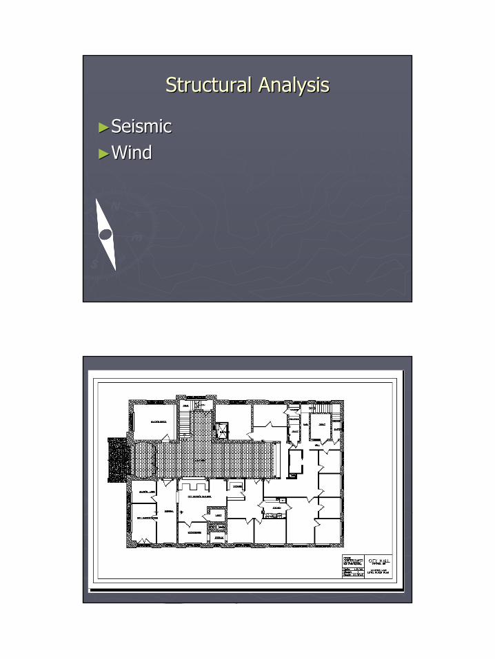
Structural AnalysisStructural Analysis
►►SeismicSeismic►►WindWind
4
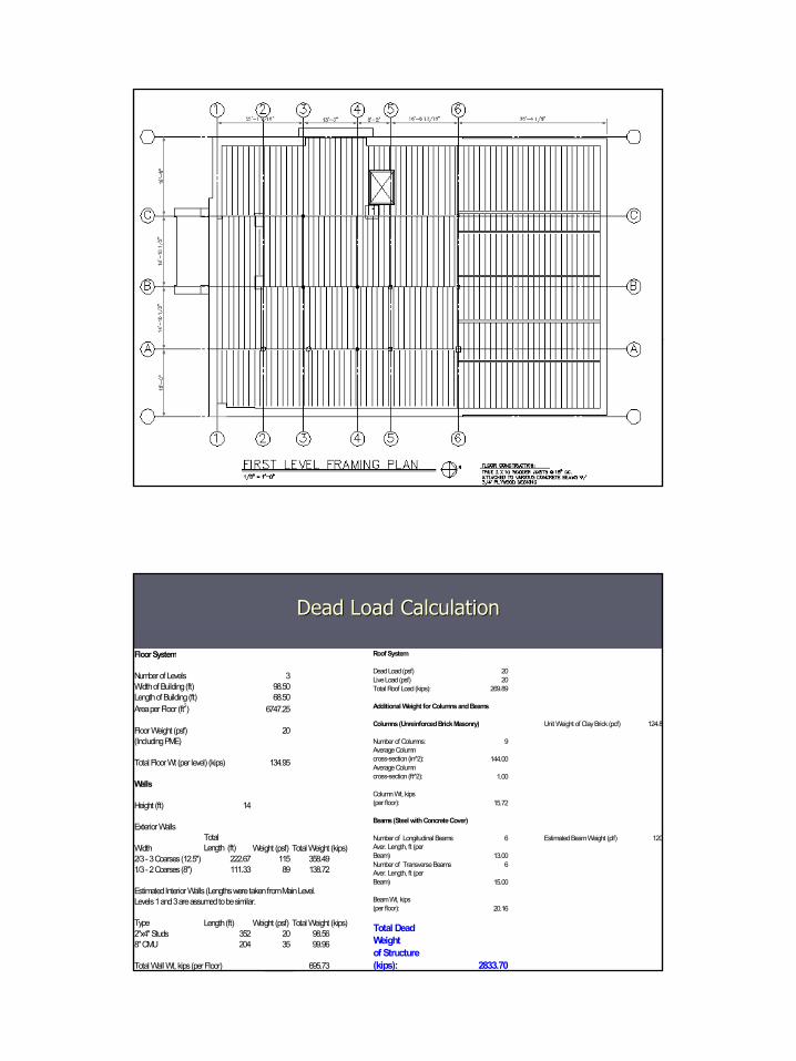
Dead Load CalculationDead Load Calculation
Floor System
Number of Levels 3Width of Building (ft) 98.50Length of Building (ft) 68.50Area per Floor (ft2) 6747.25
Floor Weight (psf) 20(Including PME)
Total Floor Wt (per level) (kips) 134.95
Walls
Height (ft) 14
Exterior Walls
Width TotalLength (ft) Weight (psf) Total Weight (kips) SBC94 pg 710 Appendix A
2/3 - 3 Coarses (12.5") 222.67 115 358.491/3 - 2 Coarses (8") 111.33 89 138.72
Type Length (ft) Weight (psf) Total Weight (kips)2"x4" Studs 352 20 98.568" CMU 204 35 99.96
Total Wall Wt, kips (per Floor) 695.73
Estimated Interior Walls (Lengths were taken from Main Level.Levels 1 and 3 are assumed to be similar.
Roof System
Dead Load (psf) 20Live Load (psf) 20Total Roof Load (kips): 269.89
Additional Weight for Columns and Beams
Columns (Unreinforced Brick Masonry) Unit Weight of Clay Brick (pcf) 124.8
Number of Columns: 9Average Column cross-section (in̂ 2): 144.00Average Column cross-section (ft̂ 2): 1.00
Column Wt, kips(per floor): 15.72
Number of Longitudinal Beams 6 Estimated Beam Weight (plf) 120Aver. Length, ft (per Beam) 13.00Number of Transverse Beams 6Aver. Length, ft (per Beam) 15.00
Beam Wt, kips (per floor): 20.16
Total Dead Weight of Structure (kips): 2833.70
Beams (Steel with Concrete Cover)
5
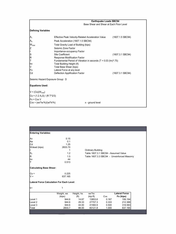
Earthquake Loads SBC94Base Shear and Shear at Each Floor Level
Defining Variables
Av Effective Peak Velocity-Related Acceleration Value (1607.1.5 SBC94)Aa Peak Acceleration (1607.1.5 SBC94)Wtotal Total Gravity Load of Building (kips)Z Seismic Zone FactorI Importance-occupancy FactorS Site Coefficient (1607.3.1 SBC94)R Response Modification FactorT Fundamental Period of Vibration in seconds (T = 0.03 (hn)^.75)hn Total Building Height (ft)V Total Base Shear (kips)Fx Lateral Force at any levelCd Deflection Applification Factor (1607.3.1 SBC94)
Seismic Hazard Exposure Group: D
Equations Used:
V = (Cs)(Wtotal)Cs = (1.2 AvS) / (R T^2/3)Fx = Cvx VCvx = (wx*hx^k)/(wi*hi^k) x - ground level
Entering Variables:
Av 0.15Aa 0.1Cd 1.25Wdead (kips) 2833.70I 1 Ordinary BuildingS2 1.2 Table 1607.3.1 SBC94 - Assumed ValueR 1.5 Table 1607.3.3 SBC94 - Unreinforced Masonry hn 44T 0.513
Calculating Base Shear:
Cs = 0.225V = 637.165
Lateral Force Calculation For Each Level:
k= 1
Weight, wx (kips)
Height, hx(ft)
wx*hx(kip-ft) Cvx
Lateral ForceFx (kips)
Level 1 944.6 14.67 13853.6 0.167 106.194Level 2 944.6 29.33 27707.3 0.333 212.388Level 3 944.6 44.00 41560.9 0.500 318.583Total 2833.7 88.00 83121.8 1.000 637.165

6
Wind Load SBC 1994 (Simplified Procedure with Height equal or less than 60 ft)
Defining Variables
q effective velocity pressureV basic wind speedI importance factorG Gust FactorGCp External Pressure CoefficientGcpi Internal Pressure Coefficient
Table 2. Pressures at Levels.
Story HeightVelocity (mph) q (psf)
1 14.67 70 102 29.34 70 123 44.01 70 13.7
Table 3. Simplified Wind Load Coefficients (GCp)
wall roof wall roofwindward
roofleeward
roofwindward
roofleeward
roof1.65 -0.4 1.1 -0.25 -1.4 -1 -1 -0.75 (Transverse Direction)1.2 -0.6 0.8 -0.35 -1.4 -0.8 -1 -0.65 (Longitudinal Direction)
Table 4. Pressure Distribution with Wind Load in Transverse DirectionLevel End Zone Interior Zone
1 16.5 112 19.8 13.23 22.605 15.07
Table 5. Pressure Distribution with Wind Load in Longitudinal DirectionLevel End Zone Interior Zone
1 12 82 14.4 9.63 16.44 10.96
*Note: Newer SBC versions and IBC use wind velocities of 90 mph.
End Zone Interior Zone End Zone Interior Zone
7
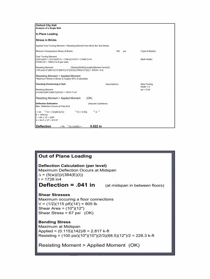
Oxford City HallAnalysis of a Single Wall
In Plane Loading
Stress in Bricks
Applied Over-Turning Moment = Resisting Moment from Brick &or Soil Stress
Mininum Compressive Stress of Bricks: 100 psi (Type N Mortar)
Over Turning Moment:(320 k)(44') + (212 k)(29.3') + (106 k)(14.67') = 21846.3 k-ft (Both Walls)21846.3/2 = 10923.2 k-ft (per wall)
Resisting Moment: (Stress)(Width)(Length)(Moment Arm)/(2)(100 psi)(12")(68.5')(12")(68.5')(12")(2/3)/((1000)(12")(2)) = 22534.1 k-ft.
Resisting Moment > Applied Moment*Maximum Stress in Bricks is roughly 50% of allowable.
Checking Overturning in Soil: Assumptions: Strip FootingWidth = 4 '
Resisting Moment: qa = 2 ksf(2 ksf)(4')(68.5')(68.5')(2/3)/2 = 12512.7 k-ft
Resisting Moment > Applied Moment (OK)
Deflection Estimation (Assume Cantilever)Max. Deflection Occurs at Free End.
I = bh 3 /12 = (12)(68.5x12) 3 /12 = 5.55e 8 in 4
E = 1400 ksiL = 44' x 12" = 528"b = 34.2' x 12" = 410.9"
Deflection = Pb 2 (3L-b)/(6EI) = 0.022 in
Out of Plane Loading
Deflection Calculation (per level)Maximum Deflection Occurs at Midspan∆ = (5(w)(l))/(384(E)(I))I = 1728 in4
Deflection = .041 in (at midspan in between floors)
Shear StressesMaximum occuring a floor connectionsV = (1/2)(115 plf)(14') = 805 lbShear Area = (10")(12")Shear Stress = 67 psi (OK)
Bending StressMaximum at MidspanApplied = (0.115)(142)/8 = 2.817 k-ftResisting = (100 psi)(10")(10")(2/3)(68.5)(12")/2 = 228.3 k-ft
Resisting Moment > Applied Moment (OK)
8
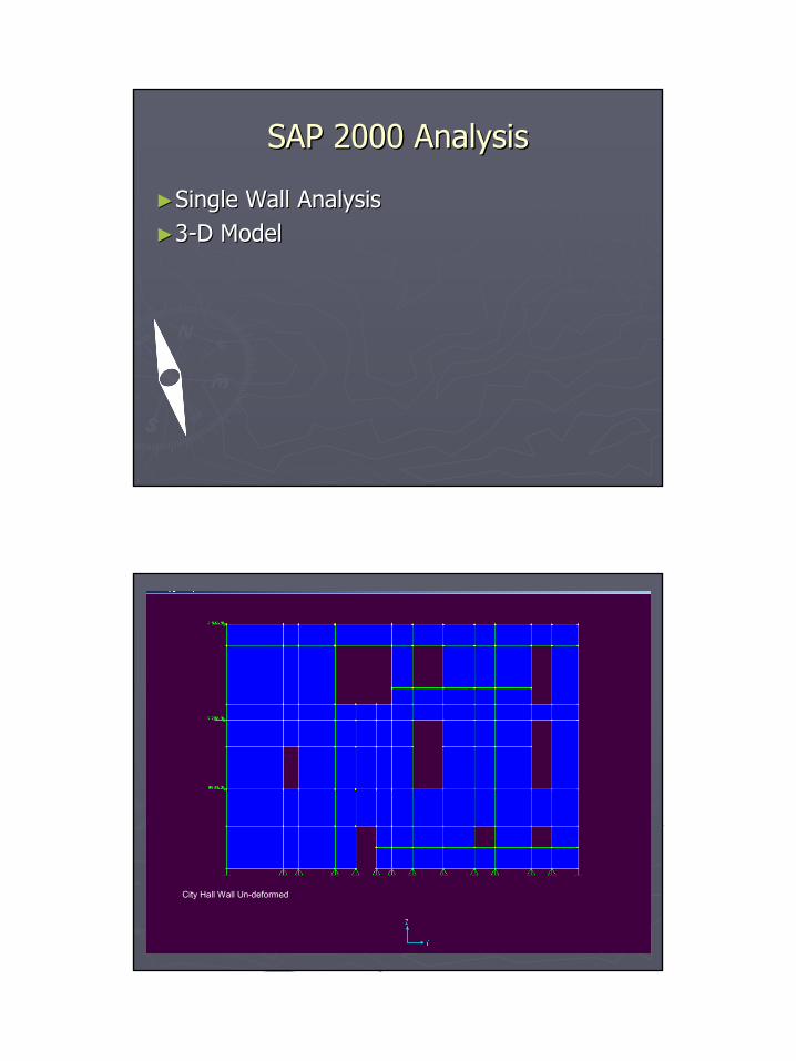
SAP 2000 AnalysisSAP 2000 Analysis
►►Single Wall AnalysisSingle Wall Analysis►►33--D ModelD Model
City Hall Wall Un-deformed
9
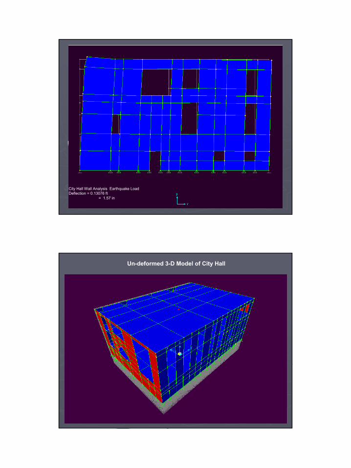
City Hall Wall Analysis Earthquake LoadDeflection = 0.13076 ft
= 1.57 in
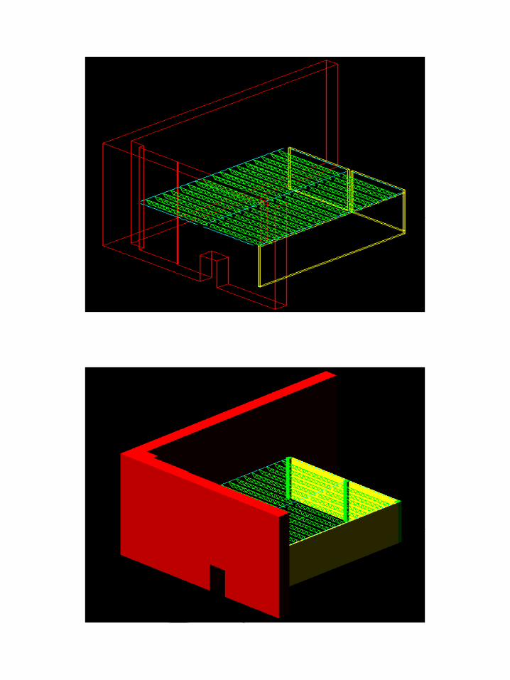
Un-deformed 3-D Model of City Hall
10
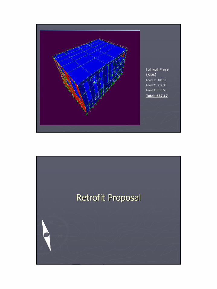
Lateral Force (kips)Level 1: 106.19
Level 2: 212.38
Level 3: 318.58
Total: 637.17
Retrofit ProposalRetrofit Proposal
11
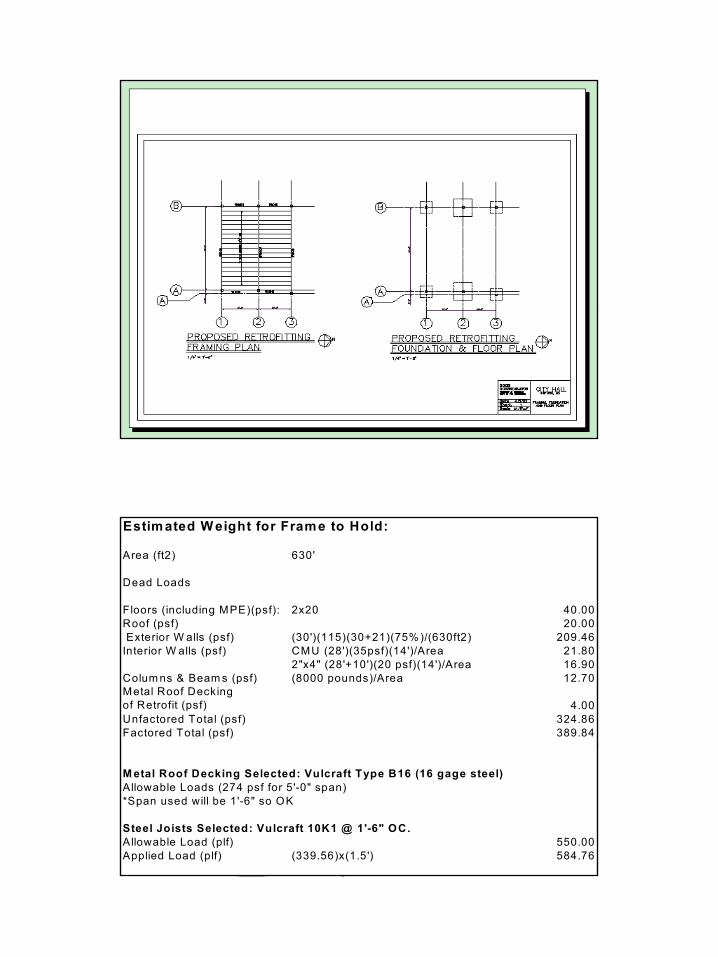
Estim ated W eight for Frame to Hold:
Area (ft2) 630'
Dead Loads
Floors (including MPE)(psf): 2x20 40.00Roof (psf) 20.00 Exterior W alls (psf) (30')(115)(30+21)(75% )/(630ft2) 209.46Interior W alls (psf) CMU (28')(35psf)(14')/Area 21.80
2"x4" (28'+10')(20 psf)(14')/Area 16.90Colum ns & Beam s (psf) (8000 pounds)/Area 12.70Metal Roof Decking of Retrofit (psf) 4.00Unfactored Total (psf) 324.86Factored Total (psf) 389.84
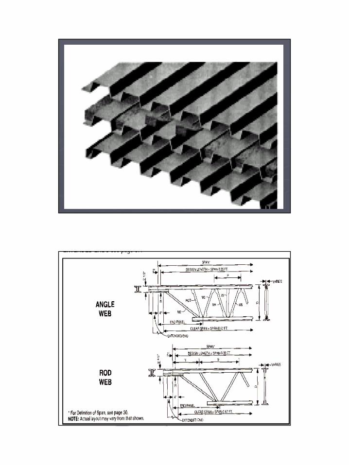
M etal Roof Decking Selected: Vulcraft Type B16 (16 gage steel)Allowable Loads (274 psf for 5'-0" span) *Span used will be 1'-6" so OK
Steel Joists Selected: Vulcraft 10K1 @ 1'-6" OC.Allowable Load (plf) 550.00Applied Load (plf) (339.56)x(1.5') 584.76
12
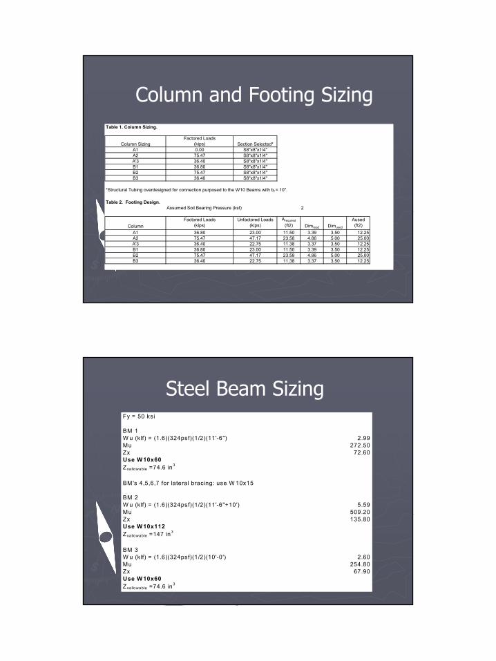
Column and Footing SizingTable 1. Column Sizing.
Column SizingFactored Loads
(kips) Section Selected*A1 0.00 S8"x8"x1/4"A2 75.47 S8"x8"x1/4"A'3 36.40 S8"x8"x1/4"B1 36.80 S8"x8"x1/4"B2 75.47 S8"x8"x1/4"B3 36.40 S8"x8"x1/4"
*Structural Tubing overdesigned for connection purposed to the W10 Beams with bf = 10".
Table 2. Footing Design.Assumed Soil Bearing Pressure (ksf) 2
ColumnFactored Loads
(kips)Unfactored Loads
(kips) Arequired
(ft2) Dimreqd Dimused
Aused (ft2)
A1 36.80 23.00 11.50 3.39 3.50 12.25A2 75.47 47.17 23.58 4.86 5.00 25.00A'3 36.40 22.75 11.38 3.37 3.50 12.25B1 36.80 23.00 11.50 3.39 3.50 12.25B2 75.47 47.17 23.58 4.86 5.00 25.00B3 36.40 22.75 11.38 3.37 3.50 12.25
Fy = 50 ksi
BM 1W u (klf) = (1.6)(324psf)(1/2)(11'-6") 2.99Mu 272.50Zx 72.60Use W 10x60Zxallowable =74.6 in3
BM's 4,5,6,7 for lateral bracing: use W 10x15
BM 2W u (klf) = (1.6)(324psf)(1/2)(11'-6"+10') 5.59Mu 509.20Zx 135.80Use W 10x112Zxallowable =147 in3
BM 3W u (klf) = (1.6)(324psf)(1/2)(10'-0') 2.60Mu 254.80Zx 67.90Use W 10x60Zxallowable =74.6 in3
Steel Beam Sizing
13
14
15
16
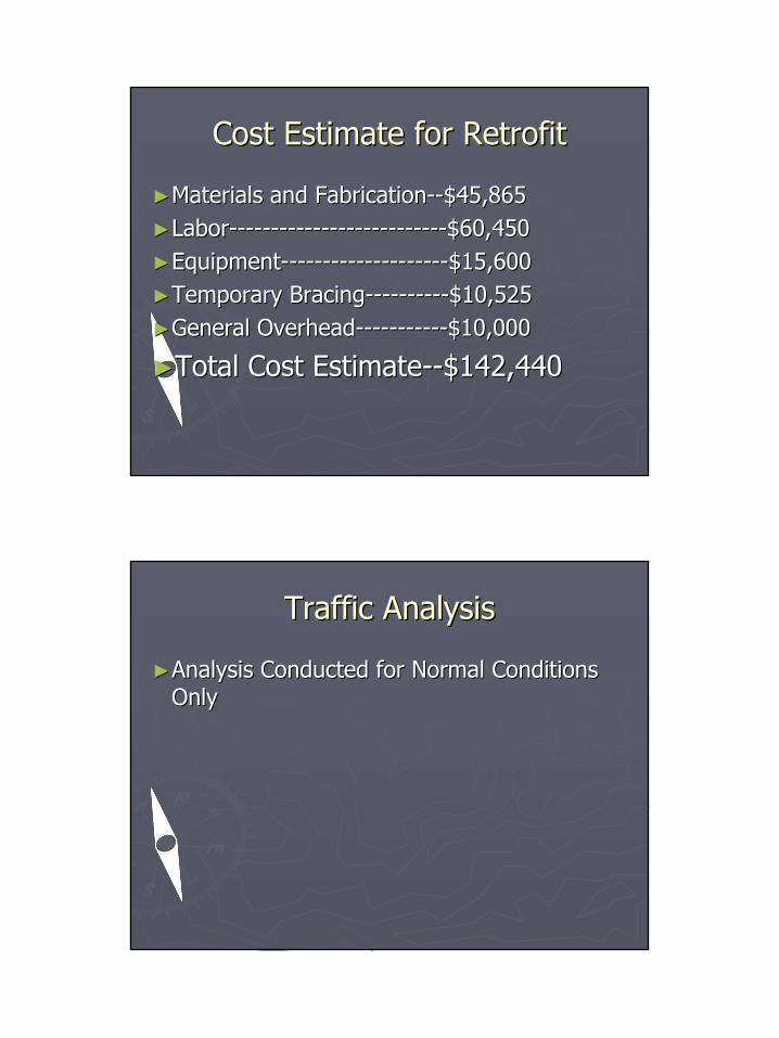
Cost Estimate for RetrofitCost Estimate for Retrofit
►►Materials and FabricationMaterials and Fabrication----$45,865$45,865►►LaborLabor----------------------------------------------------$60,450$60,450►►EquipmentEquipment----------------------------------------$15,600$15,600►►Temporary BracingTemporary Bracing--------------------$10,525$10,525►►General OverheadGeneral Overhead----------------------$10,000$10,000
►►Total Cost EstimateTotal Cost Estimate----$142,440$142,440
Traffic AnalysisTraffic Analysis
►►Analysis Conducted for Normal Conditions Analysis Conducted for Normal Conditions OnlyOnly
17
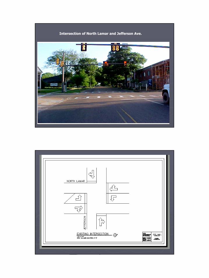
Intersection of North Lamar and Jefferson Ave.
18
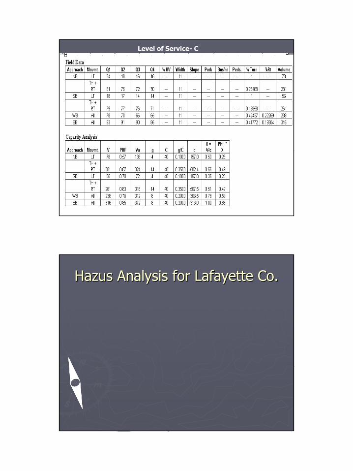
Level of Service- C
Hazus Analysis for Lafayette Co.Hazus Analysis for Lafayette Co.
19
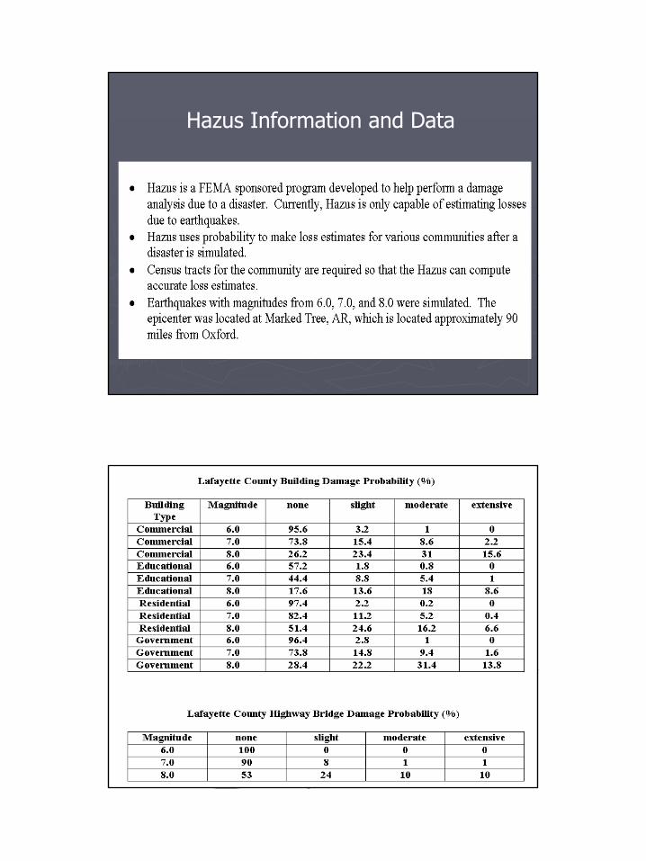
Hazus Information and Data

20
Environmental/Biological ConcernsEnvironmental/Biological Concerns
In the case of:In the case of:•• Water ContaminationWater Contamination•• Chemical Weapons Attack/Airborne Chemical Weapons Attack/Airborne
ContaminantsContaminants
21
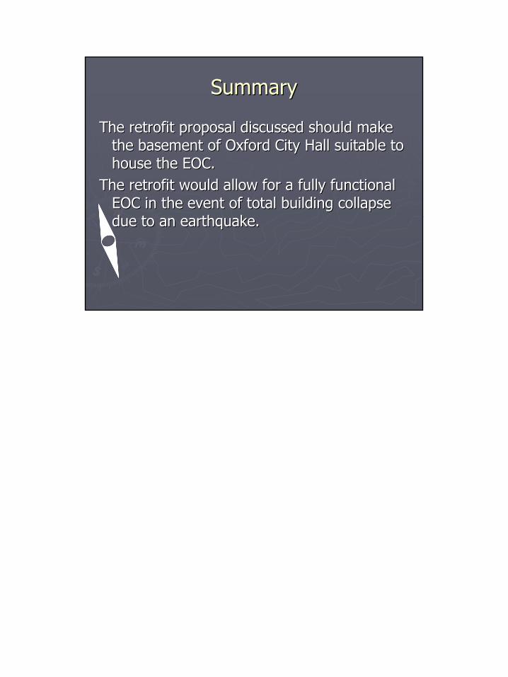
SummarySummary
The retrofit proposal discussed should make The retrofit proposal discussed should make the basement of Oxford City Hall suitable to the basement of Oxford City Hall suitable to house the EOC. house the EOC.
The retrofit would allow for a fully functional The retrofit would allow for a fully functional EOC in the event of total building collapse EOC in the event of total building collapse due to an earthquake.due to an earthquake.

![Untitled 2 [] · /01-!." *23-!." 456-!." *+,-!7" /01-!7" *23-!7" 456-!7" *+,-#!" /01-#!" *23-#!" 456-#!" *+,-##" /01-##" *23-##" 456-##" *+,-#$" /01-#$" *23-#$" 456-#$" *+,-#%" /01](https://img.pdfslide.us/doc/110x75/5f2f2b6ad0823628e27434f2/untitled-2-01-23-456-7-01-7.jpg)


![[Shinobi] Bleach 456](https://img.pdfslide.us/doc/110x75/568c37981a28ab02359c219f/shinobi-bleach-456.jpg)