Embed Size (px)
DESCRIPTION
all Standard Triumph service bulletins of the year 1963
Citation preview

TO:
BULLETIN T-63-7
ALL TRIUMPH DEALERS - WESTERN ZONE
DEPT:
SUBJECT:
DATE:
SERVICE AND PARTS
LUCAS RB340 CONTROL BOX
JANUARY 25, 1963SPITFIRE AND SPORTS SIX
Recently Lucas Service News was issued to all dealers. Please note that on the second page of the
Lucas publication a number of generator models are quoted for various makes of cars. We are,
however, only concerned with the following:
Triumph Sports Six generator C4OL regulator current setting 25 amps.
Triumph Spitfire generator C4O regulatorcurrent setting 22 amps.
The information given is applicable only to models fitted with the new type of RB340 current
regulator which is easily distinguished from the previous type on other models and therefore,
any additional information in regard to settings should be obtained from the appropriate
Workshop Manuals.

TO:
BULLETIN T-63-8
ALL TRIUMPH DEALERS - WESTERN ZONE
DEPT:
SUBJECT:
DATE:
SERVICE AND PARTS
TRIUMPH TR-4 VIBRATION
JANUARY 25, 1963
Recent investigations have confirmed that a great many of the more severetypes of front end vibration are attributable to variations in theconstruction of the tires themselves.
Wheel balancing in the normal manner can give the impression of curingthis problem on the wheel balancing machine but this need not necessarilybe the complete answer; for when normal loaded service conditions areencountered because of variations in the tire wall, deflection vibrationcontinues to be present.
Please review any outstanding front end vibration problems and handlethem in the following manner.
1.�For test purposes replace the two front wheels and tires with a pairfrom a car that is known not to exhibit this characteristic, such as ademonstrator or other such vehicle.
2.�In the event of the wheel and tire change eliminating thischaracteristic, the alleged faulty tires should be replaced byarrangements with the local representative of the tire manufacturerconcerned.
3.�In the event of there being any difficulty in obtaining a satisfactoryadjustment from the local tire dealer, contact should be made with thenearest office of the tire company concerned. The tire manufacturers haveassured us that every sympathetic treatment will be extended wheredifficulties are encountered.

TO:
BULLETIN T-63-17
ALL TRIUMPH DEALERS - WESTERN ZONE
DEPT:
SUBJECT:
DATE:
SERVICE AND PARTS
TRIUMPH 1200 & SPORTS SIX
FEBRUARY 15, 1963JUMPING OUT OF REVERSE
Service Bulletin T-62-33 details procedure for overcoming complaints ofjumping out of reverse dear on Herald or 1200 models.
A revised reverse selector shaft and plunger are now available fromSpares Division, Part Numbers l34290 (Shaft) end 136990 (Plunger).
If the fault can be dealt with in its early stages, i.e. before repeateddisengagements will have caused damage to the gears and distortion to thereverse lever fulcrum pin, adopt the following procedure:
1. Remove the gearbox cowl and detach gearbox lid.
2. Replace the existing reverse selector shaft and ball with the newshaft, l3429O, and plunger, 136990.
3. Replace the gearbox lid and cowl.
Should the gear continue to jump out, carry out the instructions detailedin Service Bulletin T-62-33, retaining the new type shaft and plunger onreassembly of the box.
Warranty allowances in accordance with Schedule of Repair Operation Timeswill apply.
TO:
BULLETIN T-63-18
ALL TRIUMPH DEALERS - WESTERN ZONE
DEPT:
SUBJECT:
DATE:
SERVICE AND PARTS
TRIUMPH 1200 - FRONT SUSPENSION
FEBRUARY 15, 1963VERTICAL LINKS
To assist standardization, the boss for locating the oil seal on thevertical link was increased from 1,380 (35 mm) to 1.500 (38 mm) atcommission numbers:
GA-45683 (drum brakes)GA-46960 (disc brakes)
The modified link can be identified by the embossed serial numbers 1 LO2157 situated on the upper leg of the link. The earlier types wereembossed with the serial number 1 LO 2129.
The two links are interchangeable with each other providing that the sealassembly, consisting of a felt seal and retainer is renewed at the sametime.
The affected part numbers are:
Vertical Link RH 205483 replaced by 209222Vertical Link LH 205484 replaced by 209223Felt Seal 100867 replaced by 132668Oil Seal Assembly107194 replaced by 132664

TO:
BULLETIN T-63-20
ALL TRIUMPH DEALERS - WESTERN ZONE
DEPT:
SUBJECT:
DATE:
SERVICE AND PARTS
SPITFIRE JACKING POINTS
MARCH 8, 1963
Since the printing of the Spitfire Owner's Handbook, the jacking pointshave been revised; thus the flanged plate in the center of the body sillhas been deleted. (Page 19, figure 19).
The new jacking points are under the front end of the sill at the bodyfixing bolt and under the rear end at the safety belt eye bolt. The nutsof these bolts should be located in the hole in the head of the jack, forsafety purposes.
All owners of Spitfires sold by you should be notified immediately of thislatest instruction, to prevent damage to the sill.

TO:
BULLETIN T-63-23
ALL TRIUMPH DEALERS - WESTERN ZONE
DEPT:
SUBJECT:
DATE:
SERVICE AND PARTS
SPITFIRE WATER SHIELDS
MARCH 20, 1963
To eliminate possible water entry into the body, rubber shields haverecently been fitted to the forward face of the �B" posts on Spitfiremodels.
These shields, part numbers 569241 L.H. and 569242 R.H. are poprivetedin position with 1/8" dia. Imex rivets AD46, as shown in the illustration.
All cars in service prior to the introduction of this scheme should bemodified to the above condition.
A warranty claim for halfanhour will be accepted.


TO:
BULLETIN T-63-25
ALL TRIUMPH DEALERS - WESTERN ZONE
DEPT:
SUBJECT:
DATE:
SERVICE AND PARTS
SPORTS SIX & SPITFIRE
MARCH 20, 1963FRONT WHEEL BEARINGS
Water may enter the front hubs between the dust shield and calipermounting bracket and damage the hub inner bearing on Spitfire and SportsSix models equipped with disc brakes. The hub outer bearing is seldomaffected.
Rectification must be carried out at two stages:
1.�Cars in Service
When rectifying a noisy front hub inner bearing:
(a)�Dismantle the front hub assemblies, renew damaged bearings anddiscard the felt seals; these will be impregnated with water.
(b)�Thoroughly coat the faces of the new felt seals with approved hubgrease. Reassemble the hubs.
(c)�Wirebrush the faces in the area of the caliper mounting plate andseal the gaps on the three sides with a suitable sealer such as �PermatexForm A Gasket."
(d)�Place a dab of red paint on the hub caps to indicate that themodification has been effected.
2.�Unsold Cars
When carrying out the Customer Preparation Service*, perform operations 1(c) and I (d). Warranty labor allowance:

TO:
BULLETIN T-63-25
ALL TRIUMPH DEALERS - WESTERN ZONE
DEPT:
SUBJECT:
DATE:
SERVICE AND PARTS
SPORTS SIX & SPITFIRE
MARCH 20, 1963FRONT WHEEL BEARINGS
Operations (a) to (d) 1 hour (each hub)
Operations (c) to (d) -1/2 hour (both sides)
NOTE
1.�The sealing operation was introduced in production at (approx.)Commission Numbers HB6800 FC-1675
2.�Builtup units, withdrawn from Spares stocks, must be sealed inaccordance with the above instructions, before being assembled tovehicles.
*�Pre Delivery Operation
The exact incorporation Commission Numbers referred in Page 1 of thisBulletin have been confirmed as FC-1936 Spitfire and HB6835 Sports Sixand therefore, no action will be necessary after these numbers.
Future production from FC-2393 and HB-7082 will incorporate a rubber sealbetween the dust shield and caliper mounting bracket. This modificationcannot be applied to prior commission numbers.
It will usually be found that only the inner bearings become damaged andunnecessary replacement of outer bearings should, therefore, be avoidedunless damage is evident.
TO:
BULLETIN T-63-31
ALL TRIUMPH DEALERS - WESTERN ZONE
DEPT:
SUBJECT:
DATE:
SERVICE AND PARTS
PAINT FORMULA TRIUMPH RACING GREEN
APRIL 12, 1963FRONT WHEEL BEARINGS
Below are details of the formulas from Rinshed-Mason and DuPont products in respect of Triumph
Racing Green. The formulas are given for both enamel and lacquer.
RINSHED-MASON
Lacquer Enamel
U38444 - Triumph Racing Green 2U3844 - Triumph Racing Green
No. 565031 No. 565031
100 Lacquer thinner 100 100 TE-01 S.S. Mix 100
407 30401 Black 507 452 TE-41 Black 552
186 30901 White 693 188 TE-21 ChineseBlue 740
156 30201 Chinese Blue 849 164 TE-71 LemonYellow 904
151 30701 Lemon Yellow 1000 96 TE-91 White 1000
DUPONT
(246)-96778-H Duco To Make (93)-96778-H Dulux To Make
Triumph Racing Green 1 Pt. Triumph Racing Green 1 Qt.
#63-H Fast Green 143 VD-5450 Additive 35
#58 Ferrite Yellow 254 #1 White 154
#65 Black(HiStrength) 347 #5 Ferrite Yellow 314
#54 White 431 #2 Black(HiStrength) 537
#49 Clear 454 #6-H Fast Green 909

TO:
BULLETIN T-63-35
ALL TRIUMPH DEALERS - WESTERN ZONE
DEPT:
SUBJECT:
DATE:
SALES, SERVICE & PARTS
LOCATION OF SPARE IGNITION AND TRUNK KEYS
JUNE 7, 1963
It has been decided at the factory that as from the week commencing May20, the spare ignition and trunk keys on all models except the TR4, willbe taped to the underside of the windshield washer bottle.
In the case of the TR-4, the spare keys will be housed in the righthandrear tail light.
Stick-on labels indicating the location of the spare ignition and trunkkeys will be affixed to the Customers' Warranty Claim form and it is hopedthat these new arrangements will eliminate complaints received concerningvehicles arriving from overseas minus the spare keys.

TO:
BULLETIN T-63-36
ALL TRIUMPH DEALERS - WESTERN ZONE
DEPT:
SUBJECT:
DATE:
SERVICE AND PARTS
TR-4 TRANSMISSIONS
JUNE 7, 1963
TR-4 Transmissions - Slipping Out of 3rd Gear
Rectification of this defect may be accomplished by replacement of theexisting 3rd and top selector ball and spring in the gearbox top cover bya plunger, part number 106481; a spring, part number 106489; a distancewasher, part number 109401. These parts are common to the Triumph 1200gearbox. The operation number applicable to this procedure is 2-206A.Gearbox Top Cover Replace at a flat rate time of 2.8 hours and includesnecessary time for removal of the tunnel cover and accessories. Thismodification has been incorporated in production from Commission NumberCT-9899. In the event of this modification not having the desiredresults, dealers should contact Zone or Distributor Service Departmentsfor further information.
Stiff Gear Changing - TR-4
Where this condition exists, a check should be made to ensure that theanti-vibration strap, which is located between the gearbox extension andgearbox mounting, is not exerting any downward distortion pressure on theextension. This condition may be readily cured by suitably packing thevibration strap mounting. The anti-vibration strap may be identified bypart number 131711, illustrated under item 74, plate L, facing page 21 inthe TR-4 Parts Catalog.
TO:
BULLETIN T-63-38
ALL TRIUMPH DEALERS - WESTERN ZONE
DEPT:
SUBJECT:
DATE:
SERVICE AND PARTS
B.30 P.S.E.I CARBURETOR
JUNE 21, 1963TRIUMPH 1200
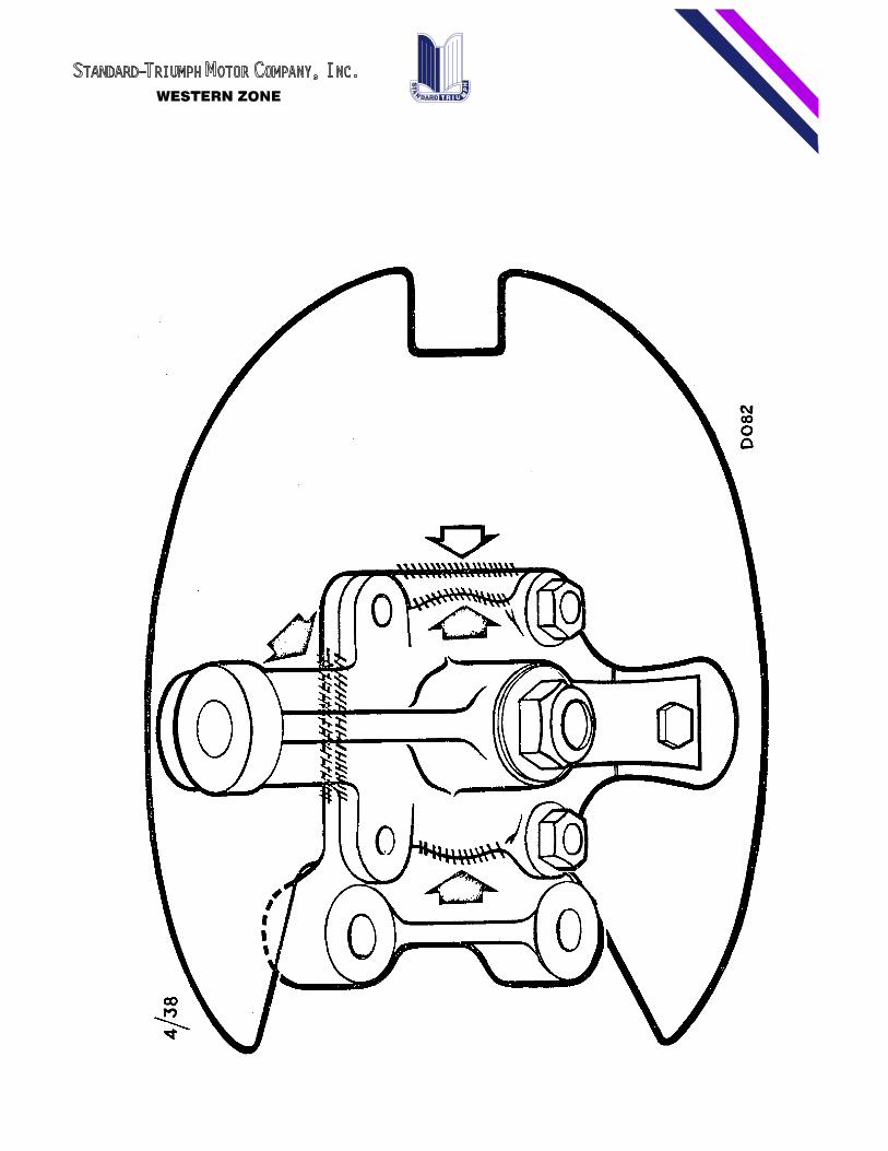
If a �flat spot" is experienced in the 35-40 m.p.h. range on light throttleopening the accelerator pump antisyphon valve should be examined.
The valve part number 510735 and its guide part number 510736, illustratedin the 1200 Spare Parts Catalog, is situated in the main body of thecarburetor above the diaphragm chamber. Its function is to preventoverspill from the injector nozzle and it should be free to move inside itsguide.
It is possible thtugh faulty threading for the guide to be screwed too farinto the carburetor body locking the valve on its seating and preventingfuel bypassing into the float chamber on light throttle opening.
To check the operation of the valve, the following procedure must beadopted:
1. Remove carburetor and float chamber lid.
2. Remove pump iniector nozzle and non-return ball valve.
3. Invert carburetor, insert a pin through the hole in the valve andcheck for movement of the valve.
4. If the valve is locked, remove the guide and replace with a newone. All current supplies from the Spares Division are correct. The valveitself need not be replaced. As an alternative 1 mm or .040" can becarefully filed off the base of the guide to allow movement of the valve.Under no circumstances must the guide be screwed back and left loose.
5. Replace the ball valve and injector nozzle and reassemblecarburetor. When refitting the lid, hold the strangler butterfly open toensure that the cam follower contacts the face of the operating camotherwise the butterfly can be locked in the closed position.
Retrospective action or exchange of the carburetor is not necessary andonly for the complaint of �flat Spot" should an investigation be madealthough fuel consumption may also be affected by inoperation of the valve.

TO:
BULLETIN T-63-39
ALL TRIUMPH DEALERS - WESTERN ZONE
DEPT:
SUBJECT:
DATE:
SERVICE AND PARTS
SPITFIRE DISTRIBUTOR POINT SETTINGS
JUNE 21, 1963
This bulletin is issued to clarify the position regarding contact breaker point setting in the
Delco Remy Distributor fitted to the Spitfire.
Although Delco Remy normally recommend a gap of .020" for their products, it is essential that
they be set at .015" on the Spitfire in conjunction with a static ignition timing of 13� B.T.D.C.
Any deviation from this recommendation will affect the ignition timing which is most critical on
this model.
The Delco Remy Distributor Manual advance adjustment is one click represents 1� crankshaft
rotation. One complete turn represents 4� crankshaft rotation.

TO:
BULLETIN T-63-40
ALL TRIUMPH DEALERS - WESTERN ZONE
DEPT:
SUBJECT:
DATE:
SERVICE AND PARTS
SPORTS SIX & SPITFIRE LIGHTING SWITCH
JUNE 28, 1963
The original switch had 5 wires, 2 of which were coded blue and whitewhich were coupled into a double connector in the main loom.
One of the blue and white wires has been deleted from the current switch,a suitable connection having been made internally.
Both the 4 and 5 wire switches are completely interchangeable and thesingle blue and white lead on switches so fitted is to be coupled to thedouble connector leaving one half blank.
All future supplies of these switches from the Spares Division will be ofthe modified type.

TO:
BULLETIN T-63-42
ALL TRIUMPH DEALERS - WESTERN ZONE
DEPT:
SUBJECT:
DATE:
PARTS AND SERVICE
HERALD, SPORTS SIX & SPITFIRE - BRAKE SQUEAK
JUNE 28, 1963
Damping shims, part number 136407, are now available from our SparesDivision for preventing squeak from the pads of disc brakes on the aboverange of vehicles.
Four shims per car are required, each one being fitted between the caliperpiston and pad, with the arrow stamped in the shim pointing to the frontof the car. After fitting, which only necessitates removal of the pads,the brake pedal must be pumped once or twice to reposition the piston inthe calipers.
Larger damping shims, which are not interchangeable, are incorporated asoriginal equipment on the TR-4 type of disc brake.

TO:
BULLETIN T-63-44
ALL TRIUMPH DEALERS - WESTERN ZONE
DEPT:
SUBJECT:
DATE:
PARTS AND SERVICE
TRIUMPH 1200 CHASSIS FRAME
JUNE 28, 1963
As a result of rationalization of frame assemblies, the Spares Divisionwill only supply a frame assembly (part numbers 401333 or 401862); or afront cross tube assembly (part number 205817).
When hood stays were introduced, the hood stop brackets were deleted fromthe front cross tube assembly (205817).
Refer to Service Bulletin T6242 when ordering a chassis frame or crosstube assembly for cars manufactured before the fitting of hood stays, twobrackets, part number 122358, must be ordered also. The brackets must bewelded to the cross tube as on the original assembly.
This information refers only to chassis frames up to commission numberGA-80000. For chassis frame details after this number reference should bemade to the Spare Parts Catalog.

TO:
BULLETIN T-63-45
ALL TRIUMPH DEALERS - WESTERN ZONE
DEPT:
SUBJECT:
DATE:
SERVICE AND PARTS
TRIUMPH 1200 AND SPORTS SIX
JUNE 28, 1963HOOD ADJUSTMENTS
The hood may be adjusted at 2 points, the rest brackets at the bulkhead and the link brackets at
the hood hinge points. Access to the link brackets at the hood hinge points necessitates removal
of both front overriders. Adjustable support stays maintain the hood in its correct position.
Elongated holes in the link plates and hood rests allow a combination of horizontal and vertical
adjustment. The ideal clearance between the hood, scuttle and door is 3/16" (4.76 mm).
The ideal clearance between the hood top edge and the scuttle is 1/2" and between the hood sidesand door leading edges is 5/16". Panel tolerances may prevent these exact dimensions being
obtained, in which case equal clearances on each side should be aimed for.
Horizontal Adjustment
Slacken the locknuts at the link plates and move the hood to the desired position either manually
or by the threaded sleeve nut, if fitted, to achieve a uniform clearance between scuttle and
hood. At this stage, the scuttle rest bracket heights may be adjusted to level the top of the hood
with the scuttle. Retighten the link bolts and locknuts.
Vertical Adjustment
To achieve a parallel clearance between the door and hood, the hood may be lifted or lowered at
the front end by slackening the link plate locknuts and moving manually to the desired position
afterwards retightening. Repositioning of the front valance will be necessary after this
adjustment has been carried out.

TO:
BULLETIN T-63-46
ALL TRIUMPH DEALERS - WESTERN ZONE
DEPT:
SUBJECT:
DATE:
SERVICE AND PARTS
SPITFIRE DISTRIBUTOR TUNING DATA
JUNE 28, 1963
The following details apply to the AC Delco Distributor fitted to theTriumph Spitfire.
Spark Plug Gap (In.) 0.025"Breaker Point Cap (In..) 0.015"Dwell Angle 38�Begin Centrifugal Advance Test(Deg. @ Crankshaft RPM) 0��- 1.5��@ 1000 R.P.M.Max. Centrifugal Advance (Deg. @Crankshaft RPM) 13��Max @ 5000 R.P.M.Begin Vacuum Advance Test (In.of Mercury) 2 - 4 ins. HGMax. Vacuum Advance (Deg. @In. Mercury) 9��- 11��@ 10 ins. HG.

TO:
BULLETIN T-63-47
ALL TRIUMPH DEALERS - WESTERN ZONE
DEPT:
SUBJECT:
DATE:
SERVICE AND PARTS
SPORTS SIX B.32 P.I.H. CARBURETORS
JUNE 28, 1963
This Service Bulletin supersedes and cancels Bulletins T6258 andT-639.
Continued investigation into the carburetion of the Sports Six has nowresulted in a revised jet setting which overcomes the problems previouslyexperienced on both pump and nonpump type carburetors.
Exhaustive tests have shown that if the carburetors are correctlysynchronized, the performance will be entirely satisfactory from everypoint of view.
The revised setting can be applied to carburetors in service whether theyare of the original pump type or the later non-pump type.
Details of the modifications to be effected are as follows:
Pump Type Carburetors
Remove the pump jets and fit blanking plugs, Part No. 512087.
Remove the 110 main jets and fit 105 main jets, Part No. 59719/105.
Remove 40 pilot jets and fit 35 pilot jets, Part No. 59720/35.
Remove 65 emulsion tubes and fit 69 emulsion tubes, Part No, 512086/69.
Remove 20 chokes and fit 18 chokes, Part No. 512542.
Disconnect and remove the accelerator pump operating rods,
Detach the operating arms from diaphragm covers by drifting out the pins,
Retune and synchronize carburetors in accordance with the instructionsgiven.
All parts needed for this modification are contained in Kit No. 512371.
NonPump Type Carburetors
Remove 20 chokes and fIt 18 chokes, part No. 512542,
Remove 112.5 main jets and fit 105 main jets, part No. 59719/105.
TO:
BULLETIN T-63-47
ALL TRIUMPH DEALERS - WESTERN ZONE
DEPT:
SUBJECT:
DATE:
SERVICE AND PARTS
SPORTS SIX B.32 P.I.H. CARBURETORS
JUNE 28, 1963
All parts needed for this modification are contained in Kit No. 512372.
Fitting Instructions
The procedure for changing the choke tubes of both pump and non-pump typecarburetors is as follows:
Remove both carburetor float covers and lift out floats.
Disconnect and remove the emulsion block from both carburetors.
With a suitable soft drift inserted through the emulsion block aperaturelightly tap the chokes until they are released from the securing leadplugs. Both chokes can now be withdrawn from the carburetor bodies.
Fit the new 18 chokes to both carburetors and secure by inserting a drift1/8" diameter in the shallow 3/16" diameter hole situated directly abovethe choke in the carburetor body. Lightly tap the lead plug until thechoke is secure.
The chokes should be inserted so that the numbers denoting their size canbe seen from the top of the carburetor, as it is possible to fit themupside down.
After modifying the carburetors, check, adjust and synchronize asfollows:
1.�Ignition timing - Sports Six 10� B.T.D.C. static. Advance slightly ontest if necessary.
2.�Valve clearances (cold) inlet -0.010"
exhaust 0.010"
Recheck when hot
3.�Starter units Ensure that bcah operating levers return to fullyclosed position.

TO:
BULLETIN T-63-47
ALL TRIUMPH DEALERS - WESTERN ZONE
DEPT:
SUBJECT:
DATE:
SERVICE AND PARTS
SPORTS SIX B.32 P.I.H. CARBURETORS
JUNE 28, 1963
4.�Jets - Ensure that all jets are perfectly clean. The smallestrestriction by foreign matter will seriously affect performance andtuning procedure.
5.�Carburetor floats - Examine both floats for damage or punctures andreplace if necessary.
6.�Needle valve height - Remove each float chamber lid, invert it andplace a straight edge across the machined face, directly over the needlevalve. The top of the needle valve should just touch the edge.
Should the needle valve lie below the straight edge by more than 0.020"(0.51 mm) fit an additional washer, Solex part No. 10593 under the valve.
7.�Float adjustment - Using a right angled and flat wood or metal block,
1-1/2" x 2" x 1/2" place the float on the block as indicated in theillustration issued with Bulletin T6258.
The pivot pin boss must lie squarely up to the edge of the block.
Set each float individua1ly to achieve symmetry between the tops andinner faces of the floats and the block.
Reassemble the carburetors and ensure that the floats move freely in thefloat chambers.
8.�Tune and synchronize carburetors - Each carburetor has two externaladjustments, the slow running screw and the mixture volume control screw.Slacken the clasping bolts on the flexible linkage between thecarburetors and disconnect the throttle return spring. With the engine atnormal working temperature, adjust each carburetor separately as follows:
(a)�Unscrew both slow running screws and ensure that the throttles areclosed by manual pressure on the screwheads.
(b)�Retighten the connecting linkage between the carburetors, takingcare that both throttles are against the stops during the process. Thesecuring bolts on the front and rear spring connectors should lie at 900to each other.

TO:
BULLETIN T-63-47
ALL TRIUMPH DEALERS - WESTERN ZONE
DEPT:
SUBJECT:
DATE:
SERVICE AND PARTS
SPORTS SIX B.32 P.I.H. CARBURETORS
JUNE 28, 1963
(c)�Gently screw the volume control screws clockwise until light contactis made with the casting seat and then unscrew them one full turn.Reconnect throttle return spring.
(d)�Screw in each slow running screw until just touching the casting stopon the body and continue by one complete turn, start the engine and adjustboth by an exactly equal amount until idling speed is 600/650 r.p.m.
(E)�Screw out both mixture volume control screws a quarter of a turn at atime until the engine begins to �hunt" indicating richness.
(f)�Screw the mixture screws in by equal amounts until the �hunting"disappears and the engine idles smoothly.
(g)�If the engine speed has now increased due to the mixture adjustment,reduce the speed to approximately 600/650 r.p.m. by adjusting each slowrunning screw by equal amounts.
(h)�If operation (g) causes any irregularity of the engine beat,readjust both volume screws equally to maintain synchronization.
9.�Hot starting - Deletion of the accelerator pump necessitatesdiscontinuing the hot starting instructions given in Service Bulletin1-62-58. Slightly depress the accelerator pedal to ensure immediatestarting of a hot engine.
The revised setting was incorporated in production from engine numberHB8585-HE.

TO:
BULLETIN T-63-48
ALL TRIUMPH DEALERS - WESTERN ZONE
DEPT:
SUBJECT:
DATE:
SERVICE AND PARTS
PAINT FORMULAS
JUNE 28, 1963
The following information covers the new additions to the Triumph colorrange.
WHITE
StandardTriumph #565032. This differs from the previous Spa White orSebring White.
Rinshed-Mason Company
Enamel #2U9925 Lacquer #U9925100 TE-01 S.S. Mix 100 Lacquer Thinner 100891 TE-91 White 991 30901 9817 TE-42 Ebony 998 30402 9922 TE-78 Indo Orange 1000 30708 1000
Ditzler
8380
DuPont
Duco (246)-97066 Delux (93)-97066
To make 1 pint To make 1 quart#82 White (Hi Hiding) 477 VD-5450 Additive 39#58 Ferrite Yellow 479.5 #12-E Green Gold 40#72 Black 481.5 #13 Black 42#55 Chrome Green 482.5 #23 White (HiHiding) 1025
JONQUIL
Standard-Triumph #565037. This is a yellow color.

TO:
BULLETIN T-63-48
ALL TRIUMPH DEALERS - WESTERN ZONE
DEPT:
SUBJECT:
DATE:
SERVICE AND PARTS
PAINT FORMULAS
JUNE 28, 1963
Rinshed-Mason Company
Enamel #2U7340 Lacquer #U7340100 TE-Ol S.S. Mix 100 Lacquer Thinner 100770 TE91 White 870 30901 91672 TE-76 Yellow Toner 942 30707 96648 TE-74 Ferrite Yellow 990 30704 98910 TE-42 Ebony 1000 30402 1000
[Ed. Note: The bulletin states �Cont'd," but no further page isavailable.]

TO:
BULLETIN T-63-49
ALL TRIUMPH DEALERS - WESTERN ZONE
DEPT:
SUBJECT:
DATE:
SERVICE AND PARTS
TR-4 STROMBERG CARBURETORS
JUNE 28, 1963
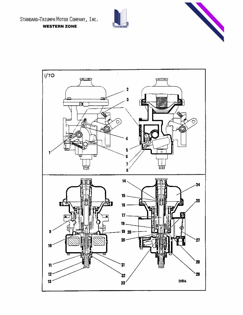
With the introduction of the Stromberg CD Carburetor on TR-4 engines, thefollowing details of design and tuning adjustments are given pendingcompletion of the Workshop Manual Supplement.
The unit functions on the constant vacuum or variable choke principle. Itis dust proof and compact and incorporates a float chamber whichsurrounds the jet orifice in place of the outrigged type of float chamberwhich is mounted away from the jet.
The float is manufactured of expanded synthetic material which eliminatesthe possibility of punctures. It is made in twin parts both being attachedto the same lever to operate the fuel valve.
The float chamber can be removed from below, leaving the float and jethousing in position. ihis arrangement simplifies cleaning and float leveladjustments.
The carburetor has a cold starting device in conjunction with thethrottle which provides a specific degree of opening to give a fast idle.The accelerator pedal should not be depressed when starting from cold.
A temporarily richer mixture to compensate for sudden throttle opening isprovided for by means of a hydraulic damper inside the hollow guide rod 17of the air valve, which should be filled with SAE 20 engine oil to within~ of the end of the rod in which the damper 14 operates.
Adjusting and Synchronizing Carburetors
This should be carried out without the air cleaners.

TO:
BULLETIN T-63-49
ALL TRIUMPH DEALERS - WESTERN ZONE
DEPT:
SUBJECT:
DATE:
SERVICE AND PARTS
TR-4 STROMBERG CARBURETORS
JUNE 28, 1963
I.�Run the engine until thoroughly warm.
2.�Slacken off the clamping bolts of the throttle spindle coupling andset the carburetors independently.
3.�Set the throttle stop screws (3) on each carburetor to the fullyclosed position and then adjust by equal amounts until an idle speed ofapproximately 600 rpm is obtained. Synchronization should be checked bylistening to the �hiss" of each carburetor which should be equal.
4.�Adjust the mixture on each carburetor by means of the jet adjustmentscrew (13). Using a suitable or small screwdriver screw up each adjustingscrew until the jet is felt to contact the inside of the air valve (18).Screw back each one approximately three turns as a basis to work on andthen finally adjust up or down until a regular and even exhaust beat isobtained.
The mixture adjustment may increase idling speed and each throttle screwmust be altered by the same amount to keep a 600 rpm tick over.
5.�The balance of the mixture should be checked by lifting each air valveapproximately 1/32" independently with a long thin screwdriver. If theengine speed rises appreciably, the mixture on the carburetor is toorich. Conversely if the engine stops, it is too weak. Readjust the jetadjusting screw down to richen the mixture and up to weaken.
6.�Hold each throttle adjusting screw against its stop and retighten thespindle clamping bolts.

TO:
BULLETIN T-63-49
ALL TRIUMPH DEALERS - WESTERN ZONE
DEPT:
SUBJECT:
DATE:
SERVICE AND PARTS
TR-4 STROMBERG CARBURETORS
JUNE 28, 1963
Float Chamber Removal
The float chamber is held to the main carburetor body by 8 screws. Therubber �0" ring (11) is situated between the jet assembly and floatchamber spigot boss to prevent fuel leakage. Care must be taken whenremoving and refitting float chamber to avoid damage.
Float Level
With the float chamber removed and the carburetors in an invertedposition, the highest point of the twin floats should be approximately9/16" (14 to 15 MM.) above the face of the main body, with the fuel inletneedle on its seating.
Care should be taken not to twist or disturb the float arms. To reset thelevel, slightly bend the tag which contacts the end of the needle (8). Asimpler method of lowering this level is the addition of a thin fiberwasher under the needle seating assembly.
Jet Centralization
Efficient operation depends on free movement of the air valve (18) andneedle (29) in the jet orifice (19).
To check freedom of the air valve, it should be lifted by means of thespring loaded pin (9) and allowed to fall freely. Failure to fall freelyindicates a sticking valve or the binding of the needle in the jetorifice. The former can be rectified by removal of the valve, cleaning theoutside of the valve and bore with kerosene or gasoline. The latter can berectified by centralizing the jet needle after first ascertaining thatthe needle is not bent.
TO:
BULLETIN T-63-49
ALL TRIUMPH DEALERS - WESTERN ZONE
DEPT:
SUBJECT:
DATE:
SERVICE AND PARTS
TR-4 STROMBERG CARBURETORS
JUNE 28, 1963
if it is found necessary to clean the diaphragm, kerosene only should beused, as the use of any other volatile cleaner such as trichlorethylenemust be avoided.
Should it be necessary to renew the jet neelle, it must be replaced withone bearing of a similar code marking.
When refitting, the shoulder of the needle must line up with the lowerface of the air valve (18).
Whenever this jet assembly is removed, it must be recentralized tofollows:
I. Lift air valve (18) and fully tighten jet assembly (12).
2. Screw up orifice adjuster until the top of the orifice (19) isjust above the bridge (28).
3. Slacken off the whole jet assembly (12) approximately - turn torelease the orifice bush (23).
4. Allow air valve (18) to fall, the needle will then enter theorifice and automatically centralize it.
5. Tighten assembly (12) slowly, checking frequently that the needleremains free in the orifice by raising air valve and allowing it to fallfreely.
6. Reset idle.
TO:
BULLETIN T-63-49
ALL TRIUMPH DEALERS - WESTERN ZONE
DEPT:
SUBJECT:
DATE:
SERVICE AND PARTS
TR-4 STROMBERG CARBURETORS
JUNE 28, 1963
Diaphragm Assembly
A bead and locating tab is moulded to both the inner and outer radii ofthe diaphragm to ensure correct location. The diaphragm is secured to theair valve by a ring and screws with lockwashers and it is essential thatthe bead is correctly positioned and the screws are tight.
Location for the bead and tab on the outer radii of the diaphragm isprovided by a channel at the top of the main body.
If the suction chamber cover is removed, it must be replaced so that thescrew holes line up with those in the main body and the diaphragm is notdisturbed.
Air Valve Rod & Guide
The air valve rod and guide must be kept clean with minimum handling whenremoved to avoid corrosion and a few drops of light oil applied to the rodwhen refitting.

TO:
BULLETIN T-63-50
ALL TRIUMPH DEALERS - WESTERN ZONE
DEPT:
SUBJECT:
DATE:
SERVICE AND PARTS
REAR ROAD SPRING - SPITFIRE
JULY 12, 1963
A small number of rear road springs that may give an incorrect rear wheelcamber might possibly be found between commission numbers FC3200 andFC5588 only.
The affected springs were confined to a small batch of springs of CockerManufacture, which is an alternative supplier of original equipment. Theother supplies are of Woodhead Manufacture and require no action. Itshould be noted that Cocker springs do not necessarily have thevariation, the condition is limited to only a small batch of them.
Identification between the two makes can be done on the car by feeling thesize of the �blister" on the top face of the second leaf adjacent to thespring eye ends. On the Woodhead spring, the �blister" is approximately3/4" diameter with an almost flat head. On the Cocker spring, the�blister" is approximately 1-1/4" diameter with an almost full domedhead.
The specified rear wheel camber for Spitfire models is 0� - 1� positivewith the car unladen but with full tank of gas.
The above camber is not adjustable and any variations or special racingrequirements can only be made by removal and replacement of the rear roadspring for reworking or exchange. Within reason, a camber variation of anegative character does not require any action but in the event of anyobviously excessive positive rear wheel camber, the following actionshould be taken under warranty arrangements. It should be noted that thiscondition will initially be readily visible by the rear wheels positionin comparison with other Spitfire and Herald models and will be found onlyon a small number of Spitfires between commission number FC-3200 andFC-5588.
TO:
BULLETIN T-63-50
ALL TRIUMPH DEALERS - WESTERN ZONE
DEPT:
SUBJECT:
DATE:
SERVICE AND PARTS
REAR ROAD SPRING - SPITFIRE
JULY 12, 1963
It is recommended that all Spitfires between FC-3200 and FC5588 thatcome in for service should be checked for this condition. In the event ofdoubt and excessive camber is apparently present, check whether thespring is of Cocker Manufacture by inspection of the �dimple" and have therear wheel camber checked accurately by the following method:
a)�The gas tank must be full or in the case of a part full tank balancemust be added in the trunk compartment as makeweight for each gallonneeded to fulfill a full tank condition.
b)�Roll the car backwards and forwards to obtain a stable condition ofthe rear suspension.
c)�Take two camber readings of each rear wheel, moving the car a fewinches between each reading to allow for wheel or tire tolerances.
d)�If the average of the two readings of each wheel is in excess of 1�positive, or the combined reading of both wheels is in excess of 2�positive, change the road spring.
A replacement spring from your Zone of Distributor will be made availablefor warranty replacement upon your advising the Service Department of thecommission number of the car concerned.
Prior warranty authorization will be given in each case (at the time ofsupplying the replacement spring) for 3 hours labor time.

TO:
BULLETIN T-63-52
ALL TRIUMPH DEALERS - WESTERN ZONE
DEPT:
SUBJECT:
DATE:
SERVICE AND PARTS
TR-4 OVERHEATING
JULY 19, 1963
Under certain conditions in some Metropolitan areas, cases have been reported of overheating.
This usually occurs in protracted traffic stoppages and no cases have been reported of this
condition arising under normal service conditions. A larger fan has now been incorporated, part
number 209792, from engine number CT21471-E, which will come in somewhere around the CT21000
commission number series.
A number of water pumps has erroneously been blamed for this condition and providing that engine
tune and timing, etc., is correct, this modification should only be required in extreme cases
and, therefore, it is not intended to handle this as a campaign.
Please pass this information to your parts manager for action.

TO:
BULLETIN T-63-53
ALL TRIUMPH DEALERS - WESTERN ZONE
DEPT:
SUBJECT:
DATE:
SERVICE AND PARTS
SPITFIRE H.S.2 S.U. CARBURETORS
AUGUST 2, 1963
A modification to the float and needle valve assembly which affects thesetting of the float level was recently introduced by the S.U. CarburetorCompany.
The parts affected are:
Float with straight lever 511742Needle and seat assembly 509102have been replaced byFloat with cranked lever 512633Needle and seat assembly 512632
Interchangeability Is affected and both units must be used as a pair orserviced Individually with the original condition.
Float level heights are also revised.
To check the level, remove lid and invert which will put the needle in theshut off condition. With the early condition, the gap between the floatlever and the face of the rim of the lid should be 1/8" (illustrated inOwner's Handbook). With the later float, the gap is increased to 3/16".

TO:
BULLETIN T-63-54
ALL TRIUMPH DEALERS - WESTERN ZONE
DEPT:
SUBJECT:
DATE:
SERVICE AND PARTS
BRAKE HOSES & CONNECTIONS
AUGUST 2, 1963TRIUMPH HERALD, TRIUMPH 1200SPORTS SIX AND SPITFIRE
Your attention is called to the necessity for checking all hydraulic pipeconnections and flexible hoses for clearance as detailed in ServiceVoucher Books for the 500 and periodical services.
Front Brake Hoses
The front wheels should be checked on full lock either way and allowancemade for maximum suspension movement. No fouling of the hoses on the tiresshould occur in any position.
Rear Brake Hoses
Examine the position of both rear brake hoses to ensure adequateclearance between hoses and halfshafts and rear springs. When assessingthe clearance, allowance must be made for full bump and reboundconditions, the former being most important and should be tested, ifadditional clearance is required, this may be obtained by resetting thehose attachment bracket on the chassis frame. it is essential that when abracket is reset, the adjacent pipe union is checked for leaks in thenormal way.
TO:
BULLETIN T-63-55
ALL TRIUMPH DEALERS - WESTERN ZONE
DEPT:
SUBJECT:
DATE:
SERVICE AND PARTS
SPITFIRE HEATER HOSES
AUGUST 22, 1963
At Commission Number FC-8274, a moulded rubber hose replaced the canvashose between the heater water valve at the bulkhead and the cylinderblock.
Please notify your Service Department that Spitfire cars betweenCommission Number FC-8274 and FCl0950, when in for service or otherwiseavailable, to ensure that the hose is not fouling the oil filler/breathercap.
Where fouling occurs, slacken the Jubilee Clip at the water valve andreset the hose to give adequate clearance.

TO:
BULLETIN T-63-56
ALL TRIUMPH DEALERS - WESTERN ZONE
DEPT:
SUBJECT:
DATE:
SERVICE AND PARTS
LICHFIELD GREEN
AUGUST 22, 1963REVISED DUPONT SPEC
Samples of the latest batch of Lichfield Green paint have been submitted toour main paint suppliers and there is only one that requires modification.This refers to the DuPont product for Lichfield Green and their formula isas follows:
(246)83738 DUCO TO MAKE (93)-83735 DULUX TO MAKELICHFIELD GREEN 1 PINT LICHFIELD GREEN 1 QUART
#54 White 289 VD-5450 Additive 37#58 Ferrite Yellow 362 #6-H Fast Green 202#65 Black (Hi Strength) 406 #2 Black (Hi Strength) 379#63-H Fast Green 436 #5 Ferrite Yellow 580#49 Clear 459 #23 White (Hi Hiding) 956

TO:
BULLETIN T-63-57
ALL TRIUMPH DEALERS - WESTERN ZONE
DEPT:
SUBJECT:
DATE:
SERVICE AND PARTS
SPITFIRE FRICTIONLESS
AUGUST 22, 1963PROPELLOR SHAFTS
Under no circumstances must the sliding portion of the frictionlesspropeller shafts fitted to the Spitfire models be removed from the mainmember. (Part Numbers 209834 and 210508).
Should any of these shafts be inadvertently dismantled, they must bereplaced by another unit as they can only be rebuilt by the manufacturers.
Any dismantled shafts returned cannot be treated as warranty procedure.

TO:
BULLETIN T-63-58
ALL TRIUMPH DEALERS - WESTERN ZONE
DEPT:
SUBJECT:
DATE:
SERVICE AND PARTS
SPORTS SIX TIMING
AUGUST 22, 1963COVER OIL SEAL
Should the necessity arise to replace the Timing Cover Oil Seal on SportsSix models, the following procedure must be observed.
1.�Remove timing cover and oil seal sleeve, part no. 133235, from thecrankshaft.
2.�Fit new seal to timing cover.
3.�Reassemble timing cover to engine.
4.�Fit sleeve with chamfer towards the crankshaft. This prevents damageto the seal.
5.�Reassemble remaining ports.
If difficulty is experienced in removing the sleeve from the crankshaft,leave it in position and use a second sleeve with the chamfer facing thefront of the car to act as a pilot when replacing the timIng cover.Otherwise, the sharp edge of the sleeve will damage the new seal..
TO:
BULLETIN T-63-59A
ALL TRIUMPH DEALERS - WESTERN ZONE
DEPT:
SUBJECT:
DATE:
SERVICE AND PARTS
TRIUMPH HERALD, TRIUMPH 1200
SEPTEMBER 6, 1963AND SPITFIRE _ GENERATORREINFORCING BRACKET
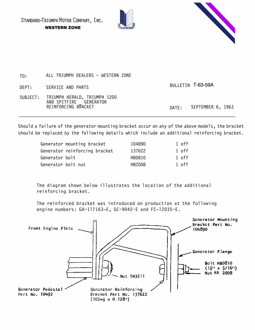
Should a failure of the generator mounting bracket occur on any of the above models, the bracket
should be replaced by the following details which include an additional reinforcing bracket.
Generator mounting bracket 104890 1 off
Generator reinforcing bracket 137622 1 off
Generator bolt HB0810 1 off
Generator bolt nut HN2008 1 off
The diagram shown below illustrates the location of the additionalreinforcing bracket.
The reinforced bracket was introduced on production at the followingengine numbers: GA-1l7163E, GC-9042-E and FCl2035-E.

TO:
BULLETIN T-63-60
ALL TRIUMPH DEALERS - WESTERN ZONE
DEPT:
SUBJECT:
DATE:
PARTS AND SERVICE
SPORTS SIX OVERDRIVE SOLENOIDS
SEPTEMBER 6, 1963
The following procedure must be followed when replacing a solenoid on aSports Six `D" type Overdlve. It does not apply to TR-4 models.
Before carrying out any dismantling obtain from the parts department abackstop plug, part number 513381 and washer 513382. (The fitting of thisbackstop was incorporated on production from Overdrive number 3330/616).
2.�Remove faulty solenoid.
3. Remove the existing hexagon headed plug and replace it with the newrecessed plug. This will reduce the excessive free movement of thesolenoid plunger.
4. Insert a 3/16" (4.76 mm) diameter peg or drill shank through the valveoperating lever locating the lever with the hole in the casing.
5. Energize the solenoid.
6. Adjust the solenoid shaft nut until its face is flush with theoperating lever.
7.�Remove the peg or drill and switch off the solenoid.
8.�Reoperate the solenoid and make sure that the hole in the lever linesup with the hole in the case.
9. Check with the ammeter connected between the solenoid and main feedwire to ensure that the solenoid points open when operated. The currentshould read approximately 2 amps.
TO:
BULLETIN T-63-60
ALL TRIUMPH DEALERS - WESTERN ZONE
DEPT:
SUBJECT:
DATE:
PARTS AND SERVICE
SPORTS SIX OVERDRIVE SOLENOIDS
SEPTEMBER 6, 1963
10.�Finally reinsert the peg or drill shank through the operating lever,locating the lever with the hole in the casing (the solenoid should not beenergized for this operation). Hold the solenoid rod hard against thebackstop plug and check the distance between the rod nut face andoperating lever face. This distance or free play must fall between .100"
.120" (2.54/3.05 mm.). Adjust by fitting plug without a washer or usingthe existing fiber washer from displaced plug, plus an additional one ifrequired.
11.�Remove the peg or drill and refix the cover plate.

TO:
BULLETIN T-63-62
ALL TRIUMPH DEALERS - WESTERN ZONE
DEPT:
SUBJECT:
DATE:
SERVICE & PARTS
DISC BRAKE WARRANTY
OCTOBER 4, 1963
All components relating to disc brakes are of Girling Manufacture and thewarranty is subject to the usual vendor terms and administration.
The Lucas/Girling warranty on disc brakes is 12 months or 12,000 miles forparts only on the usual vendor exchange basis. Labor for removal andreplacement of units is the same as for other vendor items and paid byLeylandTriumph according to the Warranty Filing Instructions.
Most common parts concerned are:
Brake padsBrake DiscsRestrictor Valves (Hydraulic Lines)Brake Calipers
As with other vendor items, overhauls should not be undertaken ifwarranty consideration is required. Replace the parts only. Lucas willexchange or repair and return parts and LTSCI will accept the laborinvolved in the repair and return the parts removal and replacement.
Brake Pads - Brake Linings
Any friction components or material such as the above is excluded fromwarranty due to the many differing conditions which can affect the life ofsuch components. In the event, however, of any unreasonable prematurewear on brake pads, where this has clearly come about by a defectiverestrictor valve, the parts may be return through the usual channels tothe vendor for special consideration. In these cases, it is necessary tosubmit the damaged parts such as brake pads together with the restrictorvalve or any such component that is considered to have caused thiscondition. It is also important that such parts are clearly tagged withthe usual vehicle detatls, owner's name, mileage, etc.

TO:
BULLETIN T-63-63
ALL TRIUMPH DEALERS - WESTERN ZONE
DEPT:
SUBJECT:
DATE:
SERVICE & PARTS
DISC BRAKE PARTS INFORMATION
OCTOBER 4, 1963
NOTE: THIS BULLETIN SUPERSEDES BULLETIN NO. T-63-30
Please make the following notation in your Triumph TR4 Parts Catalog,Part No. 510978. The information relates to Page 6 of this Catalog.
209327. Friction Disc, Front Brake Caliper. 2 off.
Alter note in remarks column to read:
Fitted from commission No. CT4690 and future (wire wheels) and from commissIon No. CT-4388 to 7746 (disc wheels)
Delete 510790. Pad Lining Assembly. 4 off.
Fitted from commission No. CT-4690 to 7629 (wire wheels and from commission No. CT4388 to 7746 (disc wheels)
134339. Pad Lining Assenbly. 4 off.
Fitted from commission No. CT-7630 (wire wheels) and fromcommission No. CT7747 (disc wheels)
130829. Pad Lining Assembly. 4 off.
Alter to read:
130829. Pad Lining Assembly (set of four) I set. Fitted up to commission No. CT-4689 (wire wheels) and CT-4387 (disc wheels) only.

TO:
BULLETIN T-63-63
ALL TRIUMPH DEALERS - WESTERN ZONE
DEPT:
SUBJECT:
DATE:
SERVICE & PARTS
DISC BRAKE PARTS INFORMATION
OCTOBER 4, 1963
l34339. Pad Lining Assembly (set of four) I set.
Fitted from commission No. CT-4690 (wire wheels) and CT-4388 (discwheels) and future.
TO:
BULLETIN T-63-64
ALL TRIUMPH DEALERS - WESTERN ZONE
DEPT:
SUBJECT:
DATE:
SERVICE & PARTS
CLUTCH REPLACEMENTS
OCTOBER 23, 1963
Further to service bulletin T-63-37 as a result of which a number ofclutch pressure plate assemblies have been returned for further factoryexamination it seems that dealers are involving themselves, customer andStandardTriumph in unnecessary expenditures. It is hoped that thefollowing notes will clear up any misunderstanding.
Clutch failures usually fall into three categories:
1.�Failure of pressure plate assembly. Evidence of this condition willclearly show breakage, cracking, bending or distortion in the unititself. The clamping pressure designed is more than adequate and slippagemust be due to a positive condition that can be observed by simpleinspection. Clutch pressure plates within the warranty period in thiscondition, can be claimed providing that it is not due to improper use andthe defect is correctly described as �pressure plate cracked" �fingerbroken", etc. Reason should not be �slipping" without fuller details.�Weak springs" are a most unlikely condition and will be subject to afactory inspection.
2.�Slipping or juddering.
a)�This is usually due to oil or grease on driven plate assembly. If oilis present on the driven plate it usually indicates defective oil seal atfront of transmission or overfilling of transmission. �Oil seal failure"in the first case would be correct description and within the warrantyperiod could be handled as such.
b)�Grease on the driven plate assembly usually indicates improperservicing cause excessive greasing of throw out cross shaft. This wouldnot carry any warranty coverage.

TO:
BULLETIN T-63-64
ALL TRIUMPH DEALERS - WESTERN ZONE
DEPT:
SUBJECT:
DATE:
SERVICE & PARTS
CLUTCH REPLACEMENTS
OCTOBER 23, 1963
The unnecessary repIacement of clutch pressure plates particularly on theTriumph TR-4 should be the concern of all.
A very small delay of clutch return and engagement must be accepted duringextra high speed upshifting on the TRT4. At reasonable speeds thischaracteristic is unnoticeable but it should not be considered as clutchslip.
All clutch claims must quote invoice number on which replacement unit waspurchased and the suspect returned to zones or distributors forexamination.
There is no question that valid claims will always be met but unnecessarycomponents for the rectification concerned will not be considered.
TO:
BULLETIN T-63-65
ALL TRIUMPH DEALERS - WESTERN ZONE
DEPT:
SUBJECT:
DATE:
SERVICE & PARTS
CHASSIS FRAMES - HERALD
OCTOBER 25, 1963
It would seem that there is still some confusion as to the correct type ofchassis frame to be used for the servicing of Herald Estate cars andconvertibles, mark II condition - i.e. from commission number 80,000 andfuture.
The original mark I chassis frame for servicing these two vehicles waspart number 401861, but with the introduction of the mark II condition allchassis frames for all Herald moddls became common. Therefore, each ofthese four types of Heralds i.e. Saloon, Estate Car, Convertible andCoupe, are serviced under part number 401987 - mark II condition.
Details are as follows:
Part No. 401333 Mark I - Saloon and Coupe up to Comm. No. 80,000Part No. 401861 Mark I - Estate & Convertible up to Comm. No. 80,000Part No. 401987 Mark II - For all Herald Models - i.e. Saloon, Estate Car,Convertible & Coupe from 80,000 and future.
The new conditions of frame are shown on pages 29A and 29B of the mainHerald 1200 Catalog, No. 510997, Second Edition. The Frame Condition401974 will not now be used as it is replaced by 401987.
Will you please record this information to avoid any possibility ofincorrect ordering in the future.

TO:
BULLETIN T-63-66
ALL TRIUMPH DEALERS - WESTERN ZONE
DEPT:
SUBJECT:
DATE:
SERVICE & PARTS
SMALL CAR MODELS
NOVEMBER 1, 1963DIFFERENTIAL DRAIN PLUG
The rear axle differential case drain plug has been deleted fromproduction on the Herald, Spitfire and Sports Six.
In future service requirements for the differential unit are reduced totopping up to correct level. Draining and refilling will not benecessary.
Drain plugs will be retained in gearboxes for these models but servicerequirements will be reduced to topping up rather than drain and refill.
Future maintenance instructions will be suitably amended.

TO:
BULLETIN T-63-67
ALL TRIUMPH DEALERS - WESTERN ZONE
DEPT:
SUBJECT:
DATE:
SERVICE & PARTS
TR-4 REAR SUSPENSION
NOVEMBER 1, 1963
The following details apply to a modification TR4 from commission numberCT23383.
Frame Assy. 1 - 306502�U" Bolts 4 - 136865R. Springs 2 - 209964Anchor Brkts. 4 - 137339Dist Piece Assy. R.H. 1 - 137634Dist Piece Assy. L.H. 1 - 137635Dist Piece Assy. 1 - 209962Dist Piece Assy. 1 - 209963Dowel 2 - 136932Check Strap 2 - 137338Set Screw 4 - 137629Nyloc Nut 4 - YN2908Brake Pipe (Bent) 1 - 210868Brake Pipe (Straight) 1 - 130822
Please ensure that your parts department registers these new numbers.

TO:
BULLETIN T-63-68
ALL TRIUMPH DEALERS - WESTERN ZONE
DEPT:
SUBJECT:
DATE:
SERVICE & PARTS
SMOG CONTROL COMPONENT LIST
NOVEMBER 6, 1963
In certain areas there are or will be shortly regulations for positivecrankcase ventilation on all cars to minimize air pollution and necessaryarrangements have been made for the incorporation of these devices in theareas concerned.
Herewith listing of the parts that have been incorporated for yourrecords for the TR4, 1200, Spitfire and Sports Six.
TR-4
100749 Setscrew - Sump to Cyl. Block 1 off132924 Plug - Crankcase Breather 1 off138073 Y piece & support bracket assy. 1 off137191 Rubber Washer (4 off)137192 Spacer (2 off) Y Piece Brkt. to air cleanerWP0008 Plain Washer (2 off) Bolt138098 Hose - Rocker Cover to Breather Pipe Extension 1 off137974 Hose - Y Piece to Air Cleaner 2 off138078 Breather Pipe Extension 1 off306527 Rocker Cover Assy. 1 off138176 Oil Filler Cap 1 off138118 Air Cleaner 2 off112892 Air Cleaner Gasket 2 offHBO825 Bolt (2 off)HB0827 Bolt - Air Cleaner & Y piece (2 off) Air CleanerHN2008 Nut (4 off) toWL0208 Lock Washer (4 off) Carb.138099 Hose - Breather Pipe Extension to Y Piece 1 off

TO:
BULLETIN T-63-68
ALL TRIUMPH DEALERS - WESTERN ZONE
DEPT:
SUBJECT:
DATE:
SERVICE & PARTS
SMOG CONTROL COMPONENT LIST
NOVEMBER 6, 1963
SPORTS SIX
138126 Blanking Plate - Crankcase Breather 1 off124954 Gasket Blanking Plate (as normal Prod.) 1 off210909 Rocker cover & joint washer assy. 1 off138176 Oil Filler Cap 1 off138100 Hose - Air Box to Rocker Cover 1 off210907 Air Box Assy. (Complete) 1 off
TRIUMPH 1200
138380 Plug - Crankcase Breather138202 Hose - Rocker Cover Air Cleaner138176 Oil Filler Cap Assy.138151 Rocker Cover & Joint Washer Assy.210862 Rocker Cover Assy.210869 Cover138171 Neck137970 Breather Pipe137833 Baffle105257 Washer210919 Air Cleaner Assy.138265 Air Cleaner Breather Pipe Assy.138201 Breather Pipe138124 Flame Trap Assy.138123 Housing138048 Gauze Assy.138049 Gauze Bottom138050 Gauze Top

TO:
BULLETIN T-63-68
ALL TRIUMPH DEALERS - WESTERN ZONE
DEPT:
SUBJECT:
DATE:
SERVICE & PARTS
SMOG CONTROL COMPONENT LIST
NOVEMBER 6, 1963
SPITFIRE
438380 Plug - Crankcase Breather138176 Oil Filler Cap Assy.138151 Rocker Cover & joint Washer Assy.210862 Rocker Cover Assy.210869 Cover131871 Neck137970 Breather Pipe137833 Baffle105257 Washer138117 Air Cleaner Assy.137594 Breather pipe138048 Gauze Asy138049 Gauze Bottom138050 Gauze Top138047 Y Piece Connection138046 Y Piece138045 Y Piece Assy.138132 Y piece Suppt. Brkt. Assy.138131 Support Bracket137191 Rubber Washer137192 Spacer138099 Hose138016 Extension138116 Hose138250 Hose

TO:
BULLETIN T-63-69
ALL TRIUMPH DEALERS - WESTERN ZONE
DEPT:
SUBJECT:
DATE:
SERVICE & PARTS
LICHFIELD GREEN PAINT
NOVEMBER 22, 1963REVISED COLOR MATCH
From latest color standard submitted to Rinshed-Mason Company, thefollowing Tintometer formula applies:
U3520 LICHFIELD GREEN (LACQUER) 2U3520 LICHFIELD GREEN (PeR-MAX)
100 Lacquer Thinner 100 100 TE-01 S.S. Mix 100467 30901 White 567 260 TE-41 Black 360194 30401 Black 761 251 TE-74 Ferrite Yellow 61139 30306 Organic Green 963 98 TE-31 Organic Green 93937 30203 Astral Blue 1000 61 TE-22 Astral Blue 1000

TO:
BULLETIN T-63-70
ALL TRIUMPH DEALERS - WESTERN ZONE
DEPT:
SUBJECT:
DATE:
SERVICE & PARTS
VENDOR ITEMS WARRANTY
NOVEMBER 22, 1963
This is a reminder that any vendor items that may be necessary to handleunder warranty should be exchanged and under no circumstances repaired.
Exchange arrangements are handled either direct with the vendor orthrough the zone office or distributor according to locality and localarrangements.
Warranty for the labor in removing and reinstalling vendor items may beclaimed in the normal manner on LTSCI claims directly with the zone officeor distributor.
The main vendor items are as follows:
Lucas Electrical
GeneratorVoltage RegulatorStarter C/W BendixHorns (Clear hooter not vendor - standard warranty procedure) All Switches and RelaysAll Lights C/W Rims, Bodies, Etc.Flasher Unit (Tung-Sol or Lucas)Batteries
Lucas Girlinq
Brake wheel cylindersBrake master cylindersClutch master cylinderClutch slave cylinderDisc brake calipers and padsBrake discBrake restrictor valveBrake hosesBrake linings C/W shoes - Please refer to bulletin T63-62

TO:
BULLETIN T-63-70
ALL TRIUMPH DEALERS - WESTERN ZONE
DEPT:
SUBJECT:
DATE:
SERVICE & PARTS
VENDOR ITEMS WARRANTY
NOVEMBER 22, 1963
Smiths - Nisonger
All instrumentsThermostatsTemperature sending unitOil pressure switchSpeedometer and tachometer - inner and outer cablesSpeedometer drive gear assembly
Armstrong
All shock absorbers
Bendix
All Bendix radios
Tires
Handled by local tire representatives

TO:
BULLETIN T-63-71
ALL TRIUMPH DEALERS - WESTERN ZONE
DEPT:
SUBJECT:
DATE:
SERVICE & PARTS
DEFECTIVE GENERATORS
NOVEMBER 22, 1963
It should be remembered that merely replacing an overheated or burnt outgenerator is not sufficient. Instances have occurred where more than onereplacement generator has been fitted to the same car and this would go onindefinitely if the cause of the failure is not rectified.
The following procedure is recommended when replacing a burnt out unit:
1.�Check control box ground.2.�Check open-circuit voltage.
3. Check that �D" and �F" leads are not crossed at the control box orgenerator. If �D" and �F" leads are crossed, the regulator contacts willweld together necessitating a replacement control box.
4. Check for short-circuit between �D" and �F" leads.
5. Check main charging leads from battery to control box. Rectify any badconnections, etc.
6. Check battery conditions as shorted cells will overload generatorcausing it to overheat.
If the control box appears to be the cause, it should be returned togetherwith the generator if both units are within the warranty period under theusual vendor arrangements. A cross reference show Id be made on theaccompanying paperwork to enable pairing of the units for investigationpurposes.

TO:
BULLETIN T-63-72
ALL TRIUMPH DEALERS - WESTERN ZONE
DEPT:
SUBJECT:
DATE:
SERVICE & PARTS
HERALD 1200 & SPORTS SIX HOOD
NOVEMBER 22, 1963LOCATING PINS AND BRACKETS
At approximately commission number GA89203 and HB-4300 hood locatingpins and brackets were incorporated, the pins being fixed to brackets onthe hood assembly and the locating brackets fixed to the scuttle panel.The pin locating brackets have a plunged tapered hole, the pin attachmentbrackets have plain holes.
To simplify adjustment of the pins, the two brackets were laterinter-changed, so that the pins were fitted to the scuttle brackets.
This alteration has raised some problems when hoods are ordered foraccidental repairs. A condition can arise when a replacement hood isreceived with the locating pin fixing brackets on the hood for a vehicleon which the pin fixing brackets are already attached to the scuttlepanel. A vice versa condition may also be encountered, i.e. locatingbrackets on the hood for a car already fitted with locating brackets onthe scuttle panels. When such a condition is met with, it is suggestedthat the scuttle brackets be modified to suit the new hood condition inpreference to attempting to change the locating brackets on the hood.
Condition A. Plain hole brackets on hood and scuttle.
Drill out spotwelds of existing scuttle brackets and fit new brackets,part numbers 706554 and 706555. It will not be possible to satisfactorilytaper the holes in the existing brackets. Fit locating pins to hoodbrackets with washers and adjust as necessary.
Condition B. Tapered hole brackets on hood and scuttle.
Fit locating pins
Disc off as much of the surplus metal on the underside of the scuttlebrackets as possible and beat flat with a hammer and metal block. Fitlocating pins together with washers and adjust as necessary.
As all hoods now being issued from the Spares Division are with thetapered hole in the hood brackets, Condition B is most probable.

TO:
BULLETIN T-63-73
ALL TRIUMPH DEALERS - WESTERN ZONE
DEPT:
SUBJECT:
DATE:
SERVICE & PARTS
FRONT SUSPENSION VERTICAL LINK
DECEMBER 6, 1963HERALD AND SPITFIRE
At commission number GA-127239, GCl2254 and FCl5576 disc brakecondition only, a revised front suspension vertical link was introduced.
Interchangeability is affected and vehicles must be serviced with theoriginal components.
The parts involved are:
Vertical link R.H. 209222 replaced by 306603Vertical link L.H. 209223 replaced by 306604Stub axle 132448 replaced by 138556Dust shield R.H. 208718 replaced by 211046Dust shield L.H. 208713 replaced by 211047Tie rod lever R.H. 205504 replaced by 211048Tie rod lever L.H. 205505 replaced by 211049
Additional details:
Water shield 138559Bolt 2 off 1385587/16" spring washer WQ0310
Drum brake front suspension assemblies are not affected by this change.
These instructions are for information only and do not constitute anauthority to carry out modifications at the expense of theStandardTriumph Motor Company, Inc.

TO:
BULLETIN T-63-74
ALL TRIUMPH DEALERS - WESTERN ZONE
DEPT:
SUBJECT:
DATE:
SERVICE & PARTS
TR-4 REAR ROAD SPRINGS
DECEMBER 6, 1963
At commission number CT-23383 recambered rear road springs with distance pieces between spring
and axle casing were introduced. This change also necessitated an alteration to the chassis
frame.
Interchangeability is affected and vehicles must be serviced with the original condition.
The affected parts are:
Frame assembly Rear Road Spring 305984 replaced by 306502
Rear Road Spring 208636
and 208637 replaced by 209964
Mounting bolt 4 off 107477 replaced by 137339 (anchor bkt)
U bolt 113194 replaced by 136865
Check strap 107476 replaced by distance pieces:
137634 R.H.
137635 L.H.
209962 R.H.
209963 L.H.
Packing piece 107861 replaced by 210868
Brake Pipe (Bent) 209870 replaced by 210868
Brake Pipe (Straight) 115403 replaced by 130822
These instructions are for information only and do not constitute an authority to carry out
modifications at the expense of the StandardTriumph Motor Company, Inc.