Embed Size (px)
Citation preview

Electronics
WORLD
www.electronicsworld.co.uk
THE ESSENTIAL ELECTRONICS ENGINEERING MAGAZINE
April 2016
Volume 122
Issue 1960
£5.60
Teledyne LeCroy Adds Revolutionary OneTouch Gesture Control To 500MHz–4GHz Oscilloscopes
SPECIAL REPORTAUTOMOTIVE
ELECTRONICS: Connectivity
Lighting
Advanced HMI
Vision processing
Technology Mobile phone charge is being extended
Regular Column This is (Not) Rocket Science
Motor control Overview and basics of different type of motors

www.electronicsworld.co.uk
CONTENTS 03
Cover supplied by TELEDYNE LECROYMore on pages 8-9
05 TREND
Driver safety begins with code security
06 TECHNOLOGY
10 REGULAR COLUMN: MCUS
by Lucio di Jacio
14 REGULAR COLUMN: WIRELESS DESIGN
by Dr Dogan Ibrahim
46 PRODUCTS
18 REVOLUTION IN MOBILITY
Since the modern automobile was invented, its basic functionality
and shape have remained essentially the same. However, the
environment in which cars operate and the data they use to
enhance the driving experience are changing dramatically.
By Alan Amici, Vice President of Engineering for Automotive
Americas at TE Connectivity
22 STRATEGIES FOR IMPLEMENTING AUTOMOTIVE LED LIGHTING SYSTEMS
By Fionn Sheerin, Senior Product Marketing Engineer at the
Analog and Interface Products Division of Microchip Technology
26 PROCESSOR EFFICIENCY AND PROGRAMMABILITY FOR COMPUTE-INTENSIVE VISION PROCESSING SUBSYSTEMS
Chris Rowen from Cadence Design Systems discusses the
ideal processor characteristics for supporting visual intelligence
applications
28 WAYS IN WHICH DRIVERS WANT MORE FROM THEIR HMIS
The design engineer’s role is constantly changing in an effort to
create more intuitive and beneficial input methods for human-
machine interfaces. By Gary Baum, VP of Myscript
32 MEASURING HYBRID ELECTRIC VEHICLE’S STABILITY WITH AN RT NAVIGATION SYSTEM
By Zhibin Miao and Hongtian Zhang from Harbin Engineering
University in China
36 A NOVEL FUZZY LOGIC MODEL FOR INTELLIGENT TRANSPORT SYSTEMS
By Umut Ozkaya and Levent Seyfi from Selcuk University in Turkey
40 BASICS OF ELECTRIC MOTOR CONTROL
Stojce Dimov Ilcev from Durban University of Technology in
South Africa gives a comprehensive overview of different type of
motors and how to best control them
Disclaimer: We work hard to ensure that the information presented in Electronics World
is accurate. However, the publisher will not take responsibility for any injury or loss of
earnings that may result from applying information presented in the magazine. It is your
responsibility to familiarise yourself with the laws relating to dealing with your customers
and suppliers, and with safety practices relating to working with electrical/electronic
circuitry – particularly as regards electric shock, fire hazards and explosions.
REGULARS
FEATURES
28
40
32


www.electronicsworld.co.uk
TREND 05
Industry pundits will say that the top overall automotive story is cybersecurity. Each
month there’s a new vulnerability, report or demonstration of just how insecure
connected cars are. From in-vehicle infotainment system hacking to penetration through
wireless vehicle services, the number of potential attack vectors grows with every vehicle
model, yet the investment into improving cybersecurity at a fundamental level – the
software itself – lags behind.
It’s not hard to fi gure out why; according to a Ponemon Institute survey, 50% of
automotive developers are either unsure or don’t believe automotive software development
teams have the skills necessary to combat software security threats. Furthermore, over 50%
of developers are not convinced that their company prioritizes secure software development
or has the enabling technologies to support it.
Everyone from manufacturers to drivers wants secure software but can’t defi ne a roadmap
to success. Software is where most errors are introduced. Not only has the volume of
delivered automotive code increased, the complexity and variety of architectures, platforms
and protocols has increased too, to where the permutations of state, behaviour, interactions
and outputs are well beyond a development team’s capabilities to test effectively.
The most crucial step is to transform teams so they understand vulnerabilities and know
how to build an effi cient test framework. A relatively small investment in training is the
difference between a team that hides from the cybersecurity reality and one smart enough to
choose the right techniques and tools to mitigate risk.
A simple test is to ask developers to restrict memory reads and writes to specifi c
locations, preventing improper access to data. While the answer may be simple, it’s the fi rst
step toward understanding that protection – and not performance – is the key to security.
Educating developers may take more time than some suppliers have, so it’s
worthwhile to investigate two familiar test techniques and adapt them to automotive.
First, while automotive teams have for some time been using coding and safety
standards, like MISRA and ISO 26262, adopting common, community-driven security
standards such as OWASP and CWE takes advantage of expert security guidelines to
quickly educate development teams on secure coding principles and provide a ready-
to-use measure of their code security. If these standards prove insuffi cient, creating
in-house, application-specifi c standards also provides a consistent, measurable
guideline for application security testing.
It can be said that some developers baulk at new standards, so the second familiar
EDITOR: Svetlana Josifovska Tel: +44 (0)1732 883392
Email: [email protected]
SALES: James CornerTel: +44 (0)20 7933 8985
Email: [email protected]
Philip WoolleyTel: +44 (0)20 7933 8989
Email: [email protected]
DESIGN: Tania King
PUBLISHER: Wayne Darroch
ISSN: 1365-4675
PRINTER: Buxton Press Ltd
SUBSCRIPTIONS:Subscription rates:
1 year: £65 (UK); £94 (worldwide)
Tel/Fax +44 (0)1635 879361/868594
Email: [email protected]
www.electronicsworld.co.uk/subscribe
Follow us on Twitter
@electrowo
Join us on LinkedIn
2nd Floor,
52-54 Gracechurch Street,
London, EC3V 0EH
‘Application Security Practices in the Automotive Industry’ by the Ponemon Institute (www.ponemon.org)
“ Over 50% of developers are not convinced that
their company prioritizes secure software development or
has the enabling technologies to support it
test technique solves three problems at the same time: effi ciency, adoption and
training. Automated testing has proved an effective way to offl oad common,
complex and, often, cumbersome work onto a controllable framework. Adapting
existing automated test-tools to include security verifi cation adds little burden on
the developer but provides useful education around secure coding practices when
a test fails. It’s this unique win-win environment that makes automated testing so
valuable.
Bringing the benefi ts of automated testing into the modern development world
of continuous integration and agile methodologies has proven effective, allowing
organisations to deliver more robust features at a faster pace. These strategies put
the burden of common or complex development tasks onto tools that perform in
the context of frequent check-ins and builds.
When switching from traditional testing methods to continuous integration,
it’s critical to adopt tools to keep up with development velocity and pare down
vulnerability rates. The good thing is that some tools have changed the way
they work to fi t incremental builds without requiring large investments in new
technologies or training. Testing by analysis has been around for years but
it’s only now that algorithm design and hardware performance is at the point
where analytic tools can perform all the checks they’re known for, security
included, against incremental builds.
Beyond education and technology, the most important point to remember is that
it pays to be paranoid. Working on the assumption that inputs to the system can’t
be trusted and that there are far more types of target environments than anyone
could possibly test for, serves to motivate more rigour in security testing and make
testing more effi cient. And that’s the next step in automotive cybersecurity, after the
software developer has evolved to be a secure software developer − fi tting in as
many comprehensive tests as possible so it’s less a question of whether the car is
secure and more a question of “what can we do next?”.
DRIVER SAFETY BEGINS WITH CODE SECURITY

06 TECHNOLOGY
April 2016
Fuel-cell technology firm Intelligent Energy
has joined forces with an undisclosed
smartphone OEM to embed hydrogen
fuel-cells into mobile devices to keep them
powered for over a week between charges.
£5.25M PROJECT PROMISES TO DELIVER WEEK-LONG MOBILE PHONE CHARGE
In the near future, mobile phones will have embedded hydrogen fuel-cells for longer-sustaining power charges
As smartphones become increasingly
loaded with more functionality and
processing demands, battery power is the first
to suffer, causing frustration for consumers.
“We believe embedding fuel cell
technology into portable devices provides
a solution to the current dilemma of
battery life. With consumers demanding
more and more from their phones, and
the advent of the Internet of Things
making the world more connected than
ever, battery innovation has not kept up.
What we offer is a solution that is clean
and efficient, and allows consumers to be
truly mobile and free from the constraints
of the grid,” said Julian Hughes, acting
Managing Director for Intelligent Energy’s
Consumer Electronics division.
Intelligent Energy has tailored a
development and integration programme,
costing £5.25m, for a specific smartphone
application to address battery limitations.
The programme will add embedded fuel
cells to an existing smartphone, resulting
in its licensing.
“We have been working with the
OEM over recent weeks, demonstrating
what our hydrogen fuel-cell technology
can achieve when embedded into a
smartphone,” added Hughes.

www.electronicsworld.co.uk
TECHNOLOGY 07
Cambridge, UK-based Plextek Consulting has
identified five key parameters necessary to make
driverless cars a reality. These are government
legislation, which must be passed to allow
autonomous vehicles on all public roads; insurers
need to accept the risks/implications of this new
level of connectivity and an entirely new model
for ownership that doesn’t make the driver/owner
responsible; manufacturers and service providers must
agree – as a partnership – to standards for resilience
to cyber-attacks; the automotive industry will need
to adopt international rules for interoperability that
ubiquitously apply across all manufacturers and vehicle
models; and manufacturers and service providers must
agree – again as a partnership – to standards for data
sharing via vehicle-to-vehicle (V2V) and vehicle-to-
infrastructure (V2I) communication. This last step also
requires end-to-end communication of critical/private
data to be authenticated by secure means.
Although many automotive companies and outsiders
to the industry, such as Google and Apple, are publicly
committed to eliminating human driving in five years
and promising fully-automated vehicles for sale by 2020,
the road to autonomous driving is not a simple one.
DRIVERLESS CARS NEED GLOBAL STANDARDS AND INTEROPERABILITY, STATES REPORT
“To realise the autonomous ‘dream’, industry
and societal stakeholders must be brought together
to discuss and resolve complex issues over safety,
security, reliability and liability to ensure this
revolutionary technology makes the leap from
concept to reality,” said Andrew Ashby, Automotive
and Transport Business Manager at Plextek
Consulting.
“To produce fully autonomous vehicle systems
where drivers or owners will reap the full benefits
− such as reduced journey times and insurance
premiums, and a healthier lifestyle − a whole new
level of integrated connectivity over and above what
Google calls an ‘autonomous car’ is a fundamental
requirement.”
Latest innovations are paving the way to
monumentally change the landscape of the
automotive industry, creating the biggest
transformation of society’s view of the vehicle in 120
years and a market worth some $42bn by 2025.
Driverless cars need global standards
08 SPONSORED FEATURE
April 2016
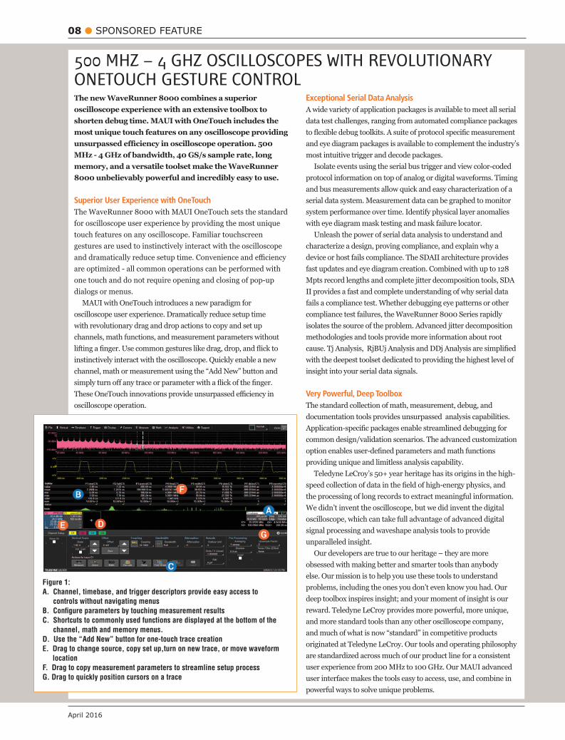
The new WaveRunner 8000 combines a superior oscilloscope experience with an extensive toolbox to shorten debug time. MAUI with OneTouch includes the most unique touch features on any oscilloscope providing
MHz - 4 GHz of bandwidth, 40 GS/s sample rate, long memory, and a versatile toolset make the WaveRunner 8000 unbelievably powerful and incredibly easy to use.
Superior User Experience with OneTouchThe WaveRunner 8000 with MAUI OneTouch sets the standard for oscilloscope user experience by providing the most unique touch features on any oscilloscope. Familiar touchscreen gestures are used to instinctively interact with the oscilloscope
are optimized - all common operations can be performed with one touch and do not require opening and closing of pop-up dialogs or menus.
MAUI with OneTouch introduces a new paradigm for oscilloscope user experience. Dramatically reduce setup time with revolutionary drag and drop actions to copy and set up channels, math functions, and measurement parameters without
channel, math or measurement using the “Add New” button and
oscilloscope operation.
Exceptional Serial Data Analysis
Isolate events using the serial bus trigger and view color-coded protocol information on top of analog or digital waveforms. Timing
serial data system. Measurement data can be graphed to monitor system performance over time. Identify physical layer anomalies
Unleash the power of serial data analysis to understand and characterize a design, proving compliance, and explain why a device or host fails compliance. The SDAII architecture provides fast updates and eye diagram creation. Combined with up to 128 Mpts record lengths and complete jitter decomposition tools, SDA II provides a fast and complete understanding of why serial data fails a compliance test. Whether debugging eye patterns or other compliance test failures, the WaveRunner 8000 Series rapidly isolates the source of the problem. Advanced jitter decomposition methodologies and tools provide more information about root
with the deepest toolset dedicated to providing the highest level of insight into your serial data signals.
Very Powerful, Deep ToolboxThe standard collection of math, measurement, debug, and documentation tools provides unsurpassed analysis capabilities.
common design/validation scenarios. The advanced customization
providing unique and limitless analysis capability.
the processing of long records to extract meaningful information.
signal processing and waveshape analysis tools to provide unparalleled insight.
Our developers are true to our heritage – they are more
else. Our mission is to help you use these tools to understand
deep toolbox inspires insight; and your moment of insight is our reward. Teledyne LeCroy provides more powerful, more unique, and more standard tools than any other oscilloscope company, and much of what is now “standard” in competitive products originated at Teledyne LeCroy. Our tools and operating philosophy are standardized across much of our product line for a consistent user experience from 200 MHz to 100 GHz. Our MAUI advanced
powerful ways to solve unique problems.
Figure 1: A. Channel, timebase, and trigger descriptors provide easy access to
controls without navigating menusB. Configure parameters by touching measurement resultsC. Shortcuts to commonly used functions are displayed at the bottom of the
channel, math and memory menus.D. Use the “Add New” button for one-touch trace creationE. Drag to change source, copy set up,turn on new trace, or move waveform
locationF. Drag to copy measurement parameters to streamline setup processG. Drag to quickly position cursors on a trace
500 MHZ – 4 GHZ OSCILLOSCOPES WITH REVOLUTIONARY ONETOUCH GESTURE CONTROL
www.electronicsworld.co.uk
SPONSORED FEATURE 09
to understand the toolsets that Teledyne LeCroy has created and deployed in our oscilloscopes. Visit our interactive website to
Powerful Mixed-Signal CapabilitiesWith embedded systems growing more complex, powerful mixed signal debug capabilities are an essential part of modern oscilloscopes. The 16 integrated digital channels and set of tools designed to view, measure and analyze analog and digital signals enable fast debugging of mixed-signal designs.
Using the powerful parallel pattern search capability of WaveScan, patterns across many digital lines can be isolated
time-stamped information, speeding up the search for each pattern occurrence. Use a variety of the many timing parameters to measure and analyze the characteristics of digital buses.
of all the digital lines simultaneously using convenient activity indicators. Simulate complete digital designs using logic gate emulation. When used with the web editor, many logic gates can be combined in one math function to simulate complex logic designs. Choose from AND, OR, NAND, NOR, XOR, NOT and D Flip Flop gates.
Flexible analog and digital cross-pattern triggering across all 20
analog signal and trigger on a digital pattern.
QualiPHY
serial buses. It guides the user through each test setup, performs each measurement in accordance with the relevant test procedure,
limits, fully documents all results, and QualiPHY helps the user perform testing the right way
The following standards are supported: ENET, USB, DDR2,
Multi-tab Display ArchitectureUnique Q-Scape multi-tab display architecture speeds up your understanding of your design with 4x the display area. Acquired or
oscilloscope grid displays, with individually selectable grid styles
2160 pixel displays.
Advanced CustomizationWith the XDEV option, third party programs can be completely
or Visual Basic without leaving the oscilloscope application - and view the results directly on the oscilloscope, in real-time.
M Models for Maximum Sample Rate and MemoryAn industry leading 40 GS/s sample rate allows for a detailed edge reconstruction even for signals with the fastest rise times. Long memory allows for maximum sample rate to be maintained in longer timebases. Deep memory of 128 Mpts is ideal for debugging long term behavior on high speed serial data buses.
teledynelecroy.com/wr8000
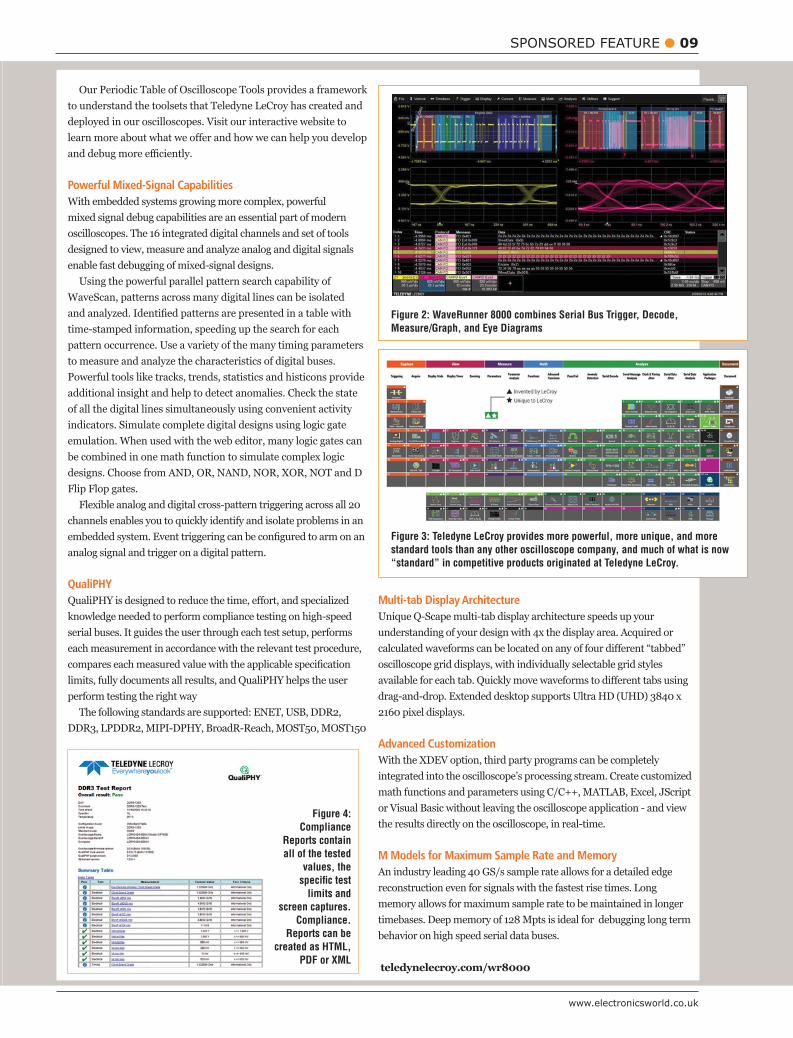
Figure 2: WaveRunner 8000 combines Serial Bus Trigger, Decode, Measure/Graph, and Eye Diagrams
Figure 4: Compliance
Reports contain all of the tested
values, the specific test
limits and screen captures.
Compliance. Reports can be
created as HTML, PDF or XML
Figure 3: Teledyne LeCroy provides more powerful, more unique, and more standard tools than any other oscilloscope company, and much of what is now “standard” in competitive products originated at Teledyne LeCroy.
10 REGULAR COLUMN: MCUs
April 2016
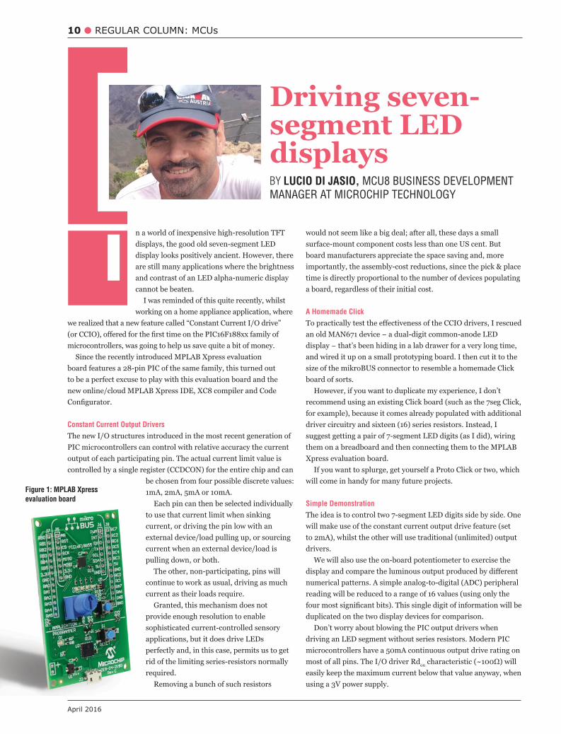
n a world of inexpensive high-resolution TFT displays, the good old seven-segment LED display looks positively ancient. However, there are still many applications where the brightness and contrast of an LED alpha-numeric display cannot be beaten.
I was reminded of this quite recently, whilst working on a home appliance application, where
we realized that a new feature called “Constant Current I/O drive”
microcontrollers, was going to help us save quite a bit of money.
to be a perfect excuse to play with this evaluation board and the
Constant Current Output Drivers
The new I/O structures introduced in the most recent generation of
output of each participating pin. The actual current limit value is controlled by a single register (CCDCON) for the entire chip and can
be chosen from four possible discrete values:
Each pin can then be selected individually to use that current limit when sinking current, or driving the pin low with an external device/load pulling up, or sourcing current when an external device/load is pulling down, or both.
The other, non-participating, pins will continue to work as usual, driving as much current as their loads require.
Granted, this mechanism does not provide enough resolution to enable sophisticated current-controlled sensory applications, but it does drive LEDs perfectly and, in this case, permits us to get rid of the limiting series-resistors normally required.
Removing a bunch of such resistors
would not seem like a big deal; after all, these days a small
board manufacturers appreciate the space saving and, more importantly, the assembly-cost reductions, since the pick & place time is directly proportional to the number of devices populating a board, regardless of their initial cost.
A Homemade Click
and wired it up on a small prototyping board. I then cut it to the
board of sorts.
for example), because it comes already populated with additional
will come in handy for many future projects.
Simple Demonstration
will make use of the constant current output drive feature (set
drivers. We will also use the on-board potentiometer to exercise the
duplicated on the two display devices for comparison.
most of all pins. The I/O driver Rdon
easily keep the maximum current below that value anyway, when using a 3V power supply.
I
Driving seven-segment LED displaysBY LUCIO DI JASIO, MCU8 BUSINESS DEVELOPMENT
MANAGER AT MICROCHIP TECHNOLOGY
Figure 1: MPLAB Xpress evaluation board
www.electronicsworld.co.uk
REGULAR COLUMN: MCUs 11
Quick Configuration With MCC
URL (https://mplabxpress.microchip.com). Logging into your MyMicrochip or MicrochipDirect account will complete the entry.
and a few mouse clicks to populate the project with the correct initialization code for the device and all the required peripherals.
Here is the procedure I followed, step by step:
input function row.
proto board. I took notice of which one went where, and I
set to the Right.
the project sources. We are now ready to focus on the core of the application.
In 10 Lines Of Code
Module table, although I expect this feature to become available very
soon. We will instead access the new control registers directly from our application, which is CCDCON, to enable/disable and set the
the purpose:
when driving the output low (negative or sink current).
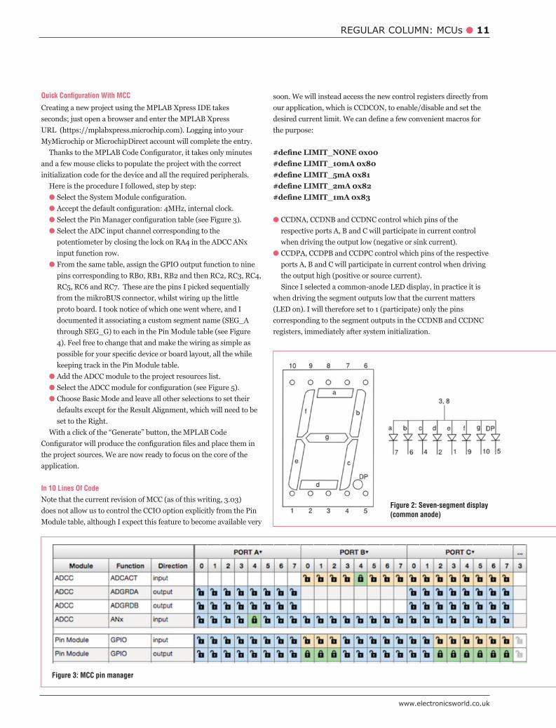
the output high (positive or source current).Since I selected a common-anode LED display, in practice it is
when driving the segment outputs low that the current matters
registers, immediately after system initialization.
Figure 2: Seven-segment display (common anode)
Figure 3: MCC pin manager

12 REGULAR COLUMN: MCUs
April 2016
void main(void){
{
}}
Listing 1: Displaying the pattern for digit ‘1’ side by side
If all goes well, this simple pre-test should bring the message
is visibly higher than that of the controlled digit, proving that current limiting is working.
Beyond 10 Lines Of Code
issues, there is an aesthetic problem with uncontrolled LED
more/all LEDs are turned on, the current in the uncontrolled LED digit (truly limited only by the driver CMOS Rdon characteristic) will divide among the diodes, resulting in a lower perceived luminous output.
Simply put, as the pattern display changes, so does the luminous output
a constant luminous output from each segment as the digit displayed changes.
To demonstrate this, we prepare a simple encoding table (matrix[])
pattern.
the correct LED segments requested, as shown in Listings 2 and 3.
Listing 2: Hex to 7-segment matrix
{
}
Listing 3: Hex digit translation
The complete application code is now a bit longer but much more
Figure 4: Pin module configuration

www.electronicsworld.co.uk
REGULAR COLUMN: MCUs 13
void main(void){
{
}}
Listing 4: Constant current drive, main.c
Figure 5: ADC configuration
Turn the potentiometer and observe how stable the luminous output produced by each display digit is as the information/pattern shown changes.
In Closing
Constant current I/O drive is only one of the many new features
particular application it helps us save eight or possibly sixteen
perhaps most importantly it speeds up board manufacturing time,
These little improvements are not as revolutionary as the Core
14 REGULAR COLUMN: WIRELESS DESIGN
April 2016
voice recognition system accepts a user’s spoken words as inputs, interprets them as commands and creates an action based on them. Simply put, voice recognition gives a system the ability to listen and understand.
Although voice recognition is not yet a perfect
home automation and some factory automation systems. For example, a typical home voice automation system allows control of household appliances, lights and other home systems by simple voice commands.
voice commands. Most voice automation systems are in the form of on/
response to voice commands.
The Advent Of IoT
With the advent of the Internet of Things (IoT) in the last decade, ubiquitous computing has become very important in our daily lives, making it necessary to simplify the human-machine interface using
is through voice. This idea can be extended to machines which can easily and simply be controlled by the human voice.
The advantages of a voice-recognition-based automation system are:
People with disabilities will be able to control their environments
Human convenience is increased since, for example, a light can be
Multi-lingual control is possible.Voice recognition systems also have some disadvantages. Even
the most sophisticated system can make errors, especially if there is
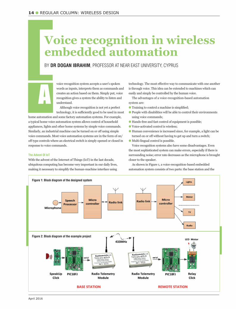
closer to the speaker.As shown in Figure 1, a voice-recognition-based embedded
automation system consists of two parts: the base station and the
A
Voice recognition in wireless embedded automationBY DR DOGAN IBRAHIM, PROFESSOR AT NEAR EAST UNIVERSITY, CYPRUS
Figure 1: Block diagram of the designed system
Figure 2: Block diagram of the example project
www.electronicsworld.co.uk
REGULAR COLUMN: WIRELESS DESIGN 15
remote station. The base station simply consists of a microphone, speech-recognition module, digital processor and a radio telemetry module. The speech-recognition module is usually programmable in the sense it can be trained with words that the module should recognise. Such modules have limited vocabularies, where the duration of each word is also limited.
At the base station, upon recognising the spoken words, the speech-recognition module composes the required commands and sends them to the processor, usually in the form of serial data. The digital processor is usually a microcontroller, which upon receiving the commands, formats them and then passes them on to the wireless radio telemetry module for transmission to the remote station.
At the remote station, a compatible radio telemetry receiver module receives the commands and passes them to the microcontroller for processing and activation. In the simplest and most common cases, electromechanical (or semiconductor-based) relays are connected to the microcontroller output ports to
alarm, washing machine, microwave, television, radio etc. In more advanced systems, sensors are used to determine the status of a controlled device to ensure it has been controlled as desired. For example, light sensors can be used to detect if the lights are on or
are in turn sent to the base station in acknowledgement. In such applications a transceiver module will be required at each station instead of a transmitter at the base station and a receiver at the remote station.
Example Voice-Recognition Automation System
Figure 2 shows the block diagram of an example voice-recognition-based automation system. At the base station a SpeakUp Click board is used. This is a voice recognition module
The module has two operation modes: standalone and click. The standalone mode is rather limited as it uses the on-board STM32415RG microcontroller I/O interface. In this example the click mode is used, with a very simple operation: words or phrases
a PC interface, and then assigned to commands. In operational mode the module listens to spoken words and
matches the sound to one of the pre-recorded commands, and then sends the index of the matched command to a selectable interface (USB or UART). The microcontroller then activates the required equipment based on this index.
A Clicker 2 for PIC18FJ microcontroller development board (based on the PIC18F87J50 microcontroller operating at 8MHz) is used in this example, with the SpeakUp Click board plugged-in to mikroBUS socket 1 (see Figure 3).
The microcontroller sends the index of the recognised command to an RF modem module (Figure 4). Although this project is based on RF radio telemetry, it is also possible to use other communications technologies, such as Wi-Fi, Bluetooth, ZigBee and others, a choice
use among others.
telemetry module receives the command and passes it to another PIC18FJ microcontroller development board. A Relay Click board is plugged into the mikroBUS socket 1 of the board. Relay Click is equipped with two electromechanical relays where one is
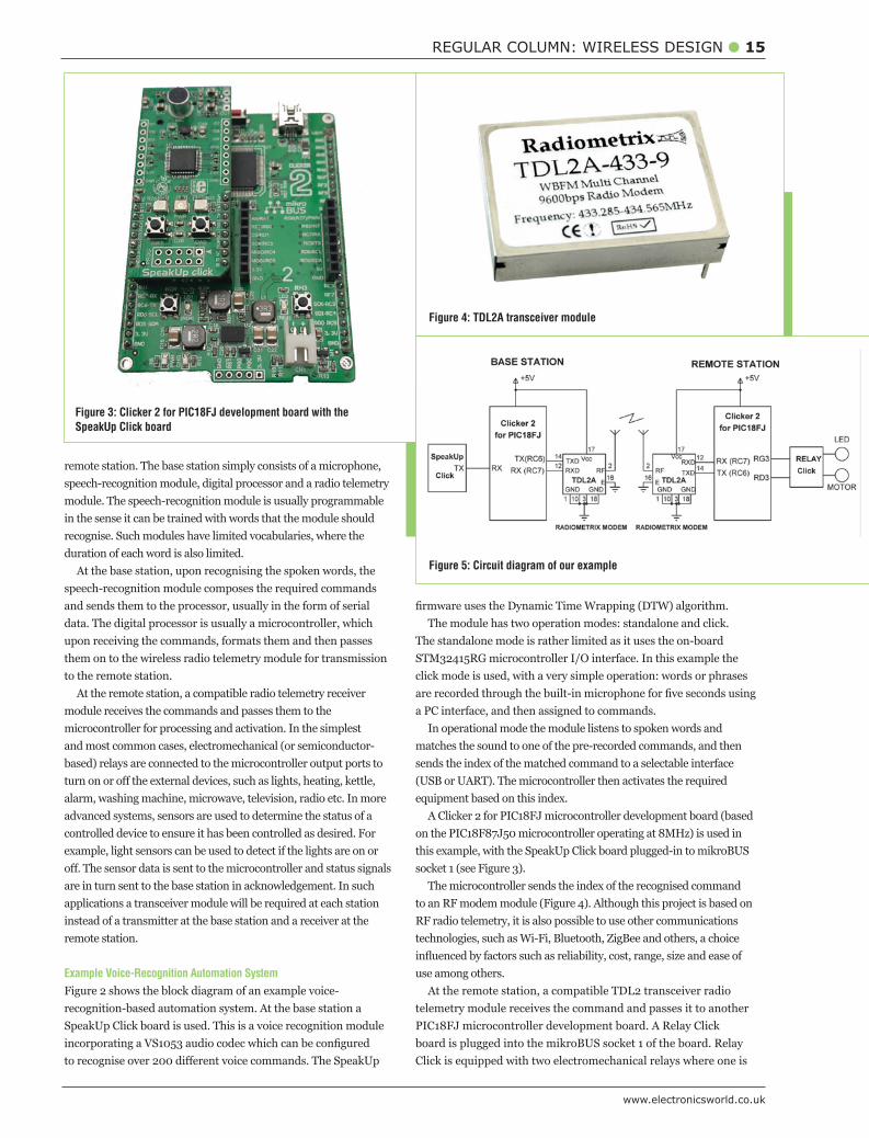
Figure 3: Clicker 2 for PIC18FJ development board with the SpeakUp Click board
Figure 4: TDL2A transceiver module
Figure 5: Circuit diagram of our example
In this example, the SpeakUp Click board is trained to recognise the following words:
Motor OFF (index 3)
Training The SpeakUp Click Board
The SpeakUp Click board can be trained by using the freely
PC. Various parameters, such as recording timeout, word length, noise level, data rate and the acceptance threshold can be set as required.
tool. These commands are then assigned to actions that will be performed when the voice is recognised. Also, a 16-bit index number of the voice command will be sent via the chosen communication interface (UART or USB).
commands, the project should be uploaded to the SpeakUp board. The command names and their indexes are in the form of a source
The Circuit Diagram
The circuit diagram of this project is shown in Figure 5. At the base station, the transmit pin of the SpeakUp board is connected to UART2 input (RG2) of the development board, and the UART1 output (RC6) is connected to the radio telemetry transmitter. At the remote station, the radio telemetry receiver passes the received command to the second development board which then activates the relays accordingly. In this project the base station transmits and the remote station receives. Some applications may need to send back acknowledgement to the base station when a command has been implemented and the required action physically taken at the remote station.
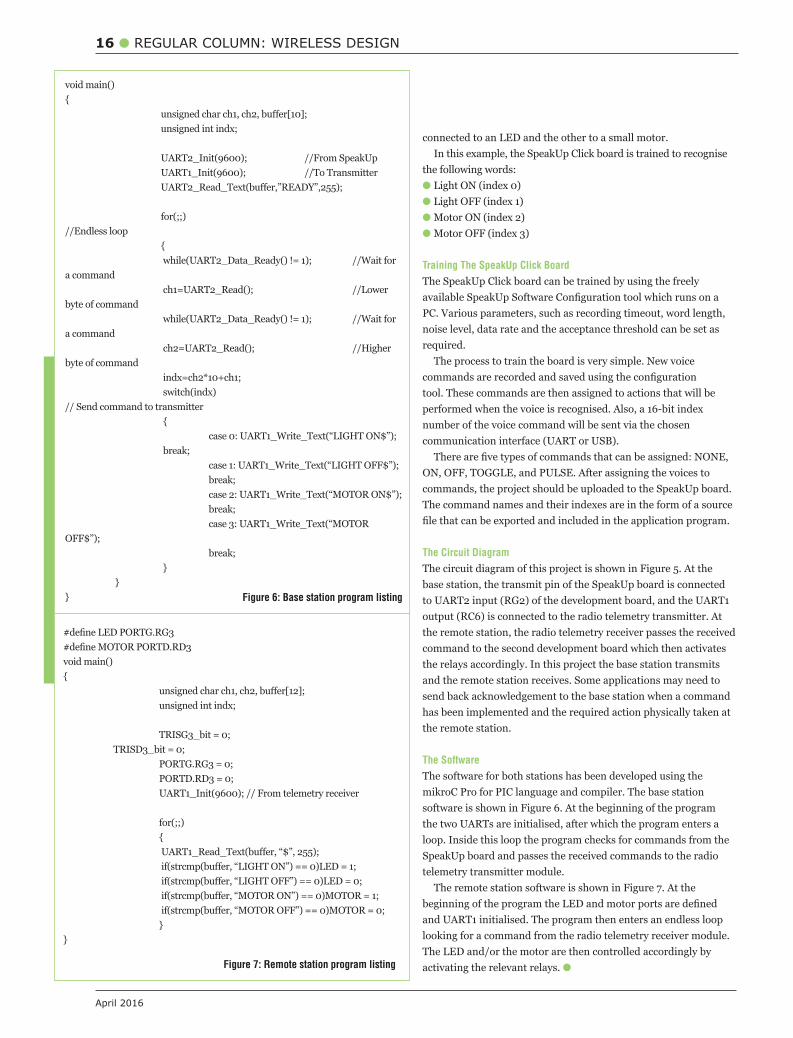
The Software
The software for both stations has been developed using the mikroC Pro for PIC language and compiler. The base station software is shown in Figure 6. At the beginning of the program the two UARTs are initialised, after which the program enters a loop. Inside this loop the program checks for commands from the SpeakUp board and passes the received commands to the radio telemetry transmitter module.
The remote station software is shown in Figure 7. At the
and UART1 initialised. The program then enters an endless loop looking for a command from the radio telemetry receiver module.
activating the relevant relays. T
16 REGULAR COLUMN: WIRELESS DESIGN
April 2016
void main(){
//Endless loop {
a command
byte of command
a command
byte of command
switch(indx) // Send command to transmitter {
case 3: UART1_Write_Text(“MOTOR
} }} Figure 6: Base station program listing
Figure 7: Remote station program listing
void main(){
{
}}

18 AUTOMOTIVE
April 2016
he connected car has the power to shake up the auto industry as profoundly as Model T (also known as Tin Lizzie, made by the Ford Motor Company between 1908 and 1927).
The implications for the connected car revolution and the outlook for its growth are strongly positive. Market
analysis house IHS Automotive predicts that sales of connected cars will grow six-fold globally by 2020. According to Gartner, by then some 250 million connected vehicles will be on roads, making connected cars a major element of the Internet of Things (IoT). But, if connected cars, equipped with Internet connectivity and sensor capabilities that share information with many sources inside and outside the vehicle, are to become as feature-rich and reliable as forecasted, car makers and OEMs must develop quality connectors and sensors to make that connectivity possible.
Inside the vehicle, sensors provide feedback that can control how and when a vehicle takes an action, from braking, steering and throttle control, to warnings and route guidance. Outside the vehicle, information is sensed and transmitted to determine position, speed, fuel level, diagnostics and a wide array of other functions.
Driving The Connected Car TrendThere are several factors that drive the trend for connected cars, among them safety, the environment and automation.
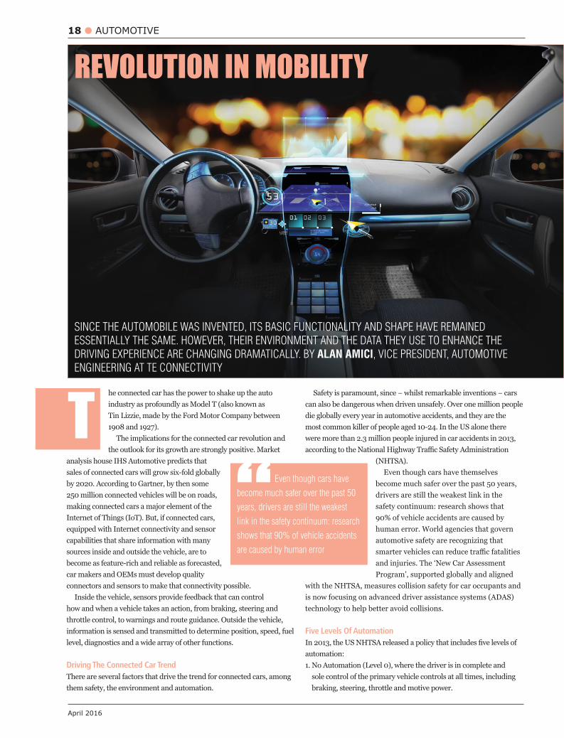
SINCE THE AUTOMOBILE WAS INVENTED, ITS BASIC FUNCTIONALITY AND SHAPE HAVE REMAINED
ESSENTIALLY THE SAME. HOWEVER, THEIR ENVIRONMENT AND THE DATA THEY USE TO ENHANCE THE
DRIVING EXPERIENCE ARE CHANGING DRAMATICALLY. BY ALAN AMICI, VICE PRESIDENT, AUTOMOTIVE
ENGINEERING AT TE CONNECTIVITY
T can also be dangerous when driven unsafely. Over one million people die globally every year in automotive accidents, and they are the most common killer of people aged 10-24. In the US alone there were more than 2.3 million people injured in car accidents in 2013,
(NHTSA).Even though cars have themselves
become much safer over the past 50 years, drivers are still the weakest link in the safety continuum: research shows that 90% of vehicle accidents are caused by human error. World agencies that govern automotive safety are recognizing that
and injuries. The ‘New Car Assessment Program’, supported globally and aligned
with the NHTSA, measures collision safety for car occupants and is now focusing on advanced driver assistance systems (ADAS) technology to help better avoid collisions.
Five Levels Of Automation
automation:1. No Automation (Level 0), where the driver is in complete and
sole control of the primary vehicle controls at all times, including braking, steering, throttle and motive power.
“ Even though cars have
become much safer over the past 50
years, drivers are still the weakest
link in the safety continuum: research
shows that 90% of vehicle accidents
are caused by human error
REVOLUTION IN MOBILITY
www.electronicsworld.co.uk
AUTOMOTIVE 19
stability control or pre-charged brakes, where the vehicle automatically assists with braking to enable the driver regain control of the vehicle or stop faster than possible by acting alone.
3. Combined-Function (Level 2), where automation covers at least two primary control functions designed to work in unison for driver release. An example of such combined functions includes adaptive cruise control in combination with lane centering.
4. Limited Self-Driving Automation (Level 3), where automation enables the driver to give up full control of all safety-critical functions under
vehicle to monitor for changes that may require the driver to take back control. The driver is expected to be available for occasional control,
limited self-driving automation.5. Full Self-Driving Automation (Level 4), where the vehicle performs
all safety-critical driving functions and monitors road conditions for an entire trip. Such a design anticipates that the driver will provide destination or navigation input, but is not expected to be available for control at any time during the trip. This includes both occupied and unoccupied vehicles.
Environment As with safety, vehicle makers, working with government regulators, have made tremendous strides in reducing polluting emissions from cars. The automotive industry is currently working to reduce greenhouse gas emissions, with a focus on vehicle weight, fuel
making cars more environmentally-friendly. Better driving habits can be enabled by data-awareness of both a car’s performance and
increase carbon dioxide (CO2) emissions and drive up costs, including costs of combating pollution. In the European Union, €80bn is spent annually due to congestion.
The EU is targeting all new cars to emit less than 95 grams of CO2 per kilometer by 2021, a 40% reduction on 2007.
A key link between connected cars and greener cars is more
infrastructure, they use less fuel and hence pollute less, because there is
Lifestyle Nowadays, consumers are used to connectivity everywhere they go and expect the same from their cars. As greater connectivity permeates their homes, such as home automation and kitchen appliances sharing data and being controlled by apps, they not only expect the same convenience and access in their cars, but anticipate their connected homes also to sync with their connected cars.
There’s a school of thought that connected cars can help people drive
conditions so they can steer clear of congestion, or choose safer routes in case of weather issues. Drivers will seek out tools that
carpooling and how many miles it is to reach the next service or charging station.
OEM Criteria As vehicle manufacturers shift resources toward technology inside the car, they must focus on three market drivers: safety, environmental requirements and lifestyle expectations. This will require a far more complex combination of hardware, software and connectivity. For example:1. Robust and reliable connectivity and sensor technologies;2. Core connectivity – essential, seamless, power signal and data;3. Reliable performance in harsh environments, such as extreme
temperature variations and vibration in rugged terrain;4. Miniaturization – ever-smaller, lighter and modular components;
6. Faster data transmission, which consumers have come to expect in their connected homes;
7. Sensing for improved performance and monitoring.
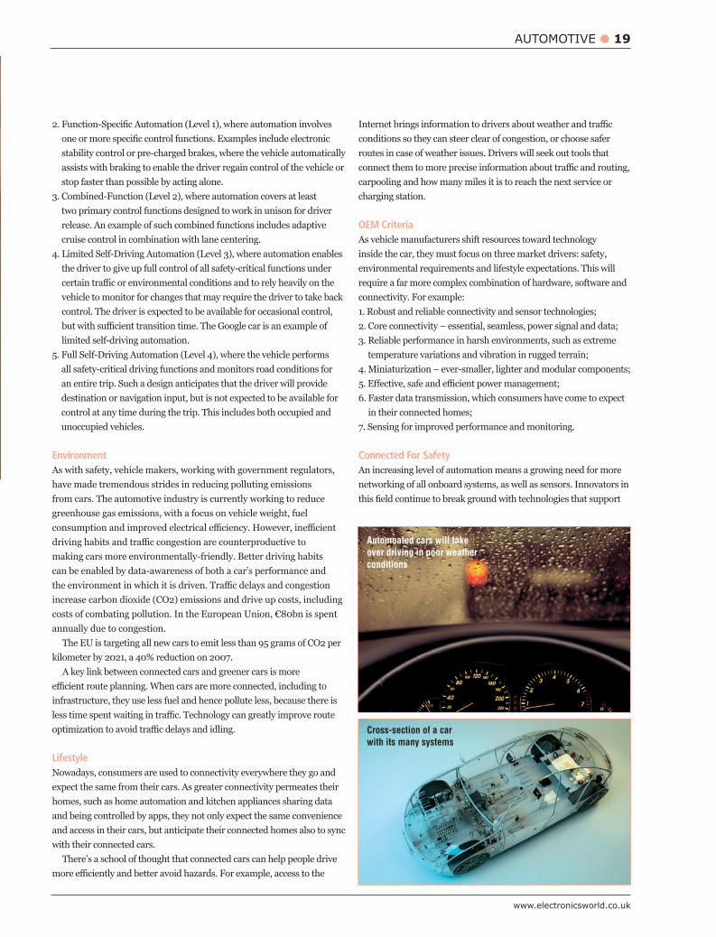
Connected For Safety An increasing level of automation means a growing need for more networking of all onboard systems, as well as sensors. Innovators in
Automoated cars will take over driving in poor weather conditions
Cross-section of a car with its many systems
20 AUTOMOTIVE
April 2016
ADAS, such as headlamps that help drivers see the road better, collision avoidance systems that automatically apply the brakes, a shift from warning systems to avoidance systems, and sensor solutions for fully automated control.
As consumers push for real-time data in their cars, car makers and technology providers need to guarantee data speeds and availability. For example, vehicles must respond immediately when a transmitted
reaction time must be a fraction of a second. Connected-car systems must be able to transmit a full gigabyte of information per second under high-vibration conditions to be considered reliable.
To contribute to safety, connected cars must also share supplementary information from WLAN or mobile telecommunication channels between the onboard electronic devices and the infrastructure (V2I) or other vehicles in the vicinity (V2V), which will
Connected cars can enhance driver and passenger safety even further. For instance, they can send alerts when children or pets are mistakenly locked inside an overheating car; they can send panic alarms in case of accidents or other unsafe situations; or can include geo-fencing options that send car owners a text if the vehicle travels beyond a set boundary.
Connected For GreenEverybody agrees that if we are committed to improving air quality,
reduce the time cars are on the road, and also requiring less fuel to
For example, it is estimated that 25% of city driving typically involves just searching for parking spaces. By building parking
cars much faster. In addition, power management technologies and
systems are closed-loop control and require sensors.Environmentally-friendly driving can also be enhanced by advanced
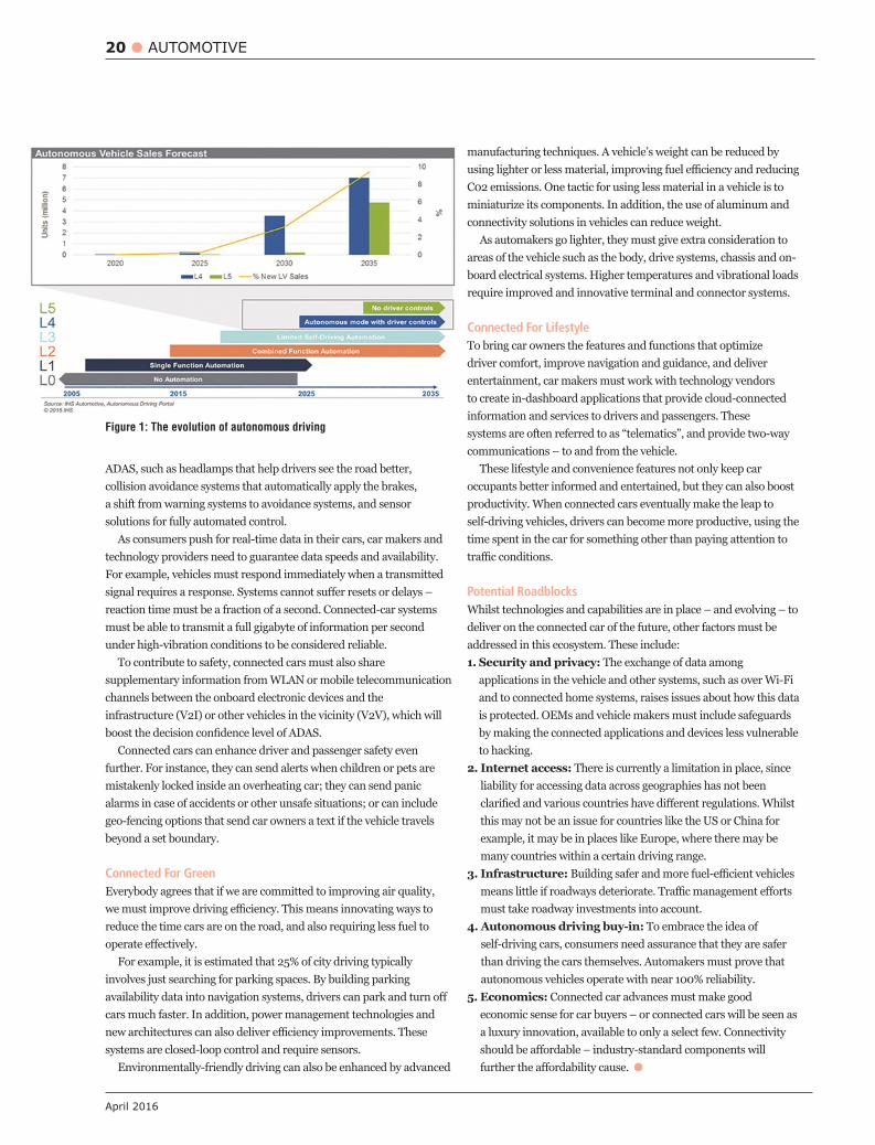
Figure 1: The evolution of autonomous driving
manufacturing techniques. A vehicle’s weight can be reduced by
C02 emissions. One tactic for using less material in a vehicle is to miniaturize its components. In addition, the use of aluminum and connectivity solutions in vehicles can reduce weight.
As automakers go lighter, they must give extra consideration to areas of the vehicle such as the body, drive systems, chassis and on-board electrical systems. Higher temperatures and vibrational loads require improved and innovative terminal and connector systems.
Connected For LifestyleTo bring car owners the features and functions that optimize driver comfort, improve navigation and guidance, and deliver entertainment, car makers must work with technology vendors to create in-dashboard applications that provide cloud-connected information and services to drivers and passengers. These systems are often referred to as “telematics”, and provide two-way communications – to and from the vehicle.
These lifestyle and convenience features not only keep car occupants better informed and entertained, but they can also boost productivity. When connected cars eventually make the leap to self-driving vehicles, drivers can become more productive, using the time spent in the car for something other than paying attention to
Potential Roadblocks Whilst technologies and capabilities are in place – and evolving – to deliver on the connected car of the future, other factors must be addressed in this ecosystem. These include:1. Security and privacy: The exchange of data among
applications in the vehicle and other systems, such as over Wi-Fi and to connected home systems, raises issues about how this data is protected. OEMs and vehicle makers must include safeguards by making the connected applications and devices less vulnerable to hacking.
2. Internet access: There is currently a limitation in place, since liability for accessing data across geographies has not been
this may not be an issue for countries like the US or China for example, it may be in places like Europe, where there may be many countries within a certain driving range.
3. Infrastructure:
must take roadway investments into account.4. Autonomous driving buy-in: To embrace the idea of
self-driving cars, consumers need assurance that they are safer than driving the cars themselves. Automakers must prove that autonomous vehicles operate with near 100% reliability.
5. Economics: Connected car advances must make good economic sense for car buyers – or connected cars will be seen as a luxury innovation, available to only a select few. Connectivity

22 AUTOMOTIVE LIGHTING
April 2016
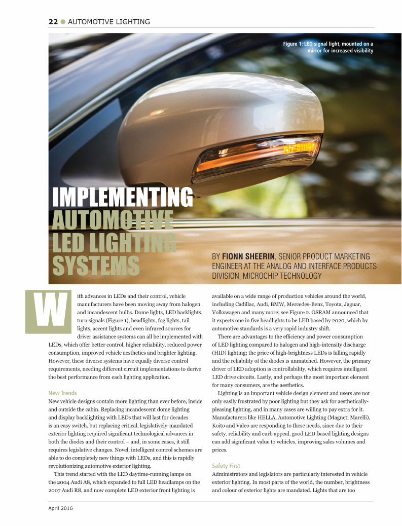
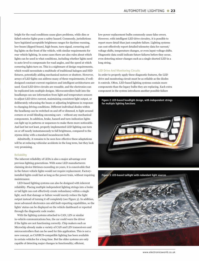
ith advances in LEDs and their control, vehicle manufacturers have been moving away from halogen and incandescent bulbs. Dome lights, LED backlights, turn signals (Figure 1), headlights, fog lights, tail lights, accent lights and even infrared sources for driver assistance systems can all be implemented with
consumption, improved vehicle aesthetics and brighter lighting. However, these diverse systems have equally diverse control
the best performance from each lighting application.
New TrendsNew vehicle designs contain more lighting than ever before, inside and outside the cabin. Replacing incandescent dome lighting and display backlighting with LEDs that will last for decades is an easy switch, but replacing critical, legislatively-mandated
requires legislative changes. Novel, intelligent control schemes are able to do completely new things with LEDs, and this is rapidly revolutionizing automotive exterior lighting.
This trend started with the LED daytime-running lamps on the 2004 Audi A8, which expanded to full LED headlamps on the 2007 Audi R8, and now complete LED exterior front lighting is
BY FIONN SHEERIN, SENIOR PRODUCT MARKETING
ENGINEER AT THE ANALOG AND INTERFACE PRODUCTS
DIVISION, MICROCHIP TECHNOLOGY
W available on a wide range of production vehicles around the world, including Cadillac, Audi, BMW, Mercedes-Benz, Toyota, Jaguar, Volkswagen and many more; see Figure 2. OSRAM announced that
automotive standards is a very rapid industry shift.
of LED lighting compared to halogen and high-intensity discharge (HID) lighting; the price of high-brightness LEDs is falling rapidly and the reliability of the diodes is unmatched. However, the primary driver of LED adoption is controllability, which requires intelligent LED drive circuits. Lastly, and perhaps the most important element for many consumers, are the aesthetics.
Lighting is an important vehicle design element and users are not only easily frustrated by poor lighting but they ask for aesthetically-pleasing lighting, and in many cases are willing to pay extra for it. Manufacturers like HELLA, Automotive Lighting (Magneti Marelli), Koito and Valeo are responding to these needs, since due to their safety, reliability and curb appeal, good LED-based lighting designs
prices.
Safety FirstAdministrators and legislators are particularly interested in vehicle exterior lighting. In most parts of the world, the number, brightness and colour of exterior lights are mandated. Lights that are too
IMPLEMENTING AUTOMOTIVE LED LIGHTING SYSTEMS
Figure 1: LED signal light, mounted on a mirror for increased visibility
www.electronicsworld.co.uk
AUTOMOTIVE LIGHTING 23
bright for the road conditions cause glare problems, while dim or failed exterior lights pose a safety hazard. Commonly, jurisdictions have legislated acceptable brightness ranges for daytime-running, low-beam (dipped-beam), high-beam, turn-signal, cornering and fog lights on the front of the vehicle, with similar requirements for rear vehicle lighting. In some cases there are also rules about which lights can be used in what conditions, including whether lights need to auto-level to compensate for road angles, and the speed at which cornering lights turn on. This is a nightmare of design requirements, which would necessitate a multitude of traditional halogen and HID
arrays of LED lights can address many of these requirements, if well-designed constant-current regulators and intelligent architectures are used. Good LED drive circuits are reusable, and the electronics can be replicated into multiple designs. Microcontrollers built into the headlamps can use information from light and temperature sensors to adjust LED drive current, maintaining consistent light output, or deliberately refocusing the beam or adjusting brightness in response
components. In addition, brake, hazard and turn-indication lights can light up in patterns or sequences to make them more noticeable. And last but not least, properly implemented LED lighting can turn
250ms delay with a standard incandescent bulb.
will be at reducing vehicular accidents in the long term, but they look very promising.
ReliabilityThe inherent reliability of LEDs is also a major advantage over previous lighting generations. With some LED manufacturers claiming device lifetimes exceeding 20 years, it is conceivable that in the future vehicle lights would not require replacement. Factory-installed lights could last as long as the power train, without requiring maintenance.
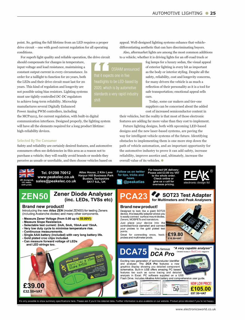
LED-based lighting systems can also be designed with inherent reliability. Placing multiple independent lighting strings into a brake
light, such that damage or failure would merely reduce the light
more advanced electronics can add fault-reporting capabilities, so the lights’ status can be displayed on the vehicle dashboard or reported through the diagnostic code reader.
With the lighting systems attached to CAN, LIN or similar in-vehicle communications bus, the car could warn the driver if the lights are not functioning correctly. Chip makers such as Microchip already make a variety of CAN and LIN transceivers and microcontrollers that can be used for this application. This is not a new concept, as CANBUS-compatible lighting has been available in certain vehicles for a long time. But the older systems are only
low-power replacement bulbs commonly cause false errors. However, with intelligent LED drive circuitry, it is possible to report more detail than just complete failure. Lighting systems
voltage shifts, temperature changes, or even input-voltage shifts. Diagnostic data could indicate future failures before they occur, even detecting minor changes such as a single shorted LED in a long string.
LED Drive And Monitoring CircuitsIn order to properly apply these diagnostic features, the LED drive and monitoring circuit must be as reliable as the diodes it controls. Often, LED-based lighting systems contain more components than the legacy bulbs they are replacing. Each extra component in the system introduces another possible failure
Figure 2: LED-based headlight design, with independent strings for multiple lighting functions
Figure 3: LED-based taillight with redundant light sources

www.electronicsworld.co.uk
AUTOMOTIVE LIGHTING 25
point. So, getting the full lifetime from an LED requires a proper
conditions. For superb light quality and reliable operation, the drive circuit
should compensate for changes in temperature, input voltage and load resistance, maintaining a constant output current in every circumstance. In order for a taillight to function for 20 years, both the LEDs and their drive circuit must last for 20 years. This kind of regulation and longevity are not possible using bias resistors. Lighting systems must use tightly-controlled DC-DC regulators to achieve long-term reliability. Microchip manufactures several Digitally Enhanced
communication interfaces. Designed properly, the lighting system
high-reliability devices.
Selected By The ConsumerSafety and reliability are certainly desired features, and automotive
perceive as unsafe or unreliable, and then choose vehicles based on
fog lamps for a luxury sedan, the visual appeal of exterior lighting is every bit as important as the body or interior styling. Despite all the safety, reliability, cost and longevity concerns, for many drivers the vehicle is as much a
safe transportation; emotional appeal sells cars.
Today, some car makers and tier-one suppliers can be concerned about the added cost of increased semiconductor content in
their vehicles, but the reality is that most of those electronic features are adding far more value than they cost to implement.
path of vehicle automation, and an important opportunity for the automotive industry to prove it can add safety, increase reliability, improve ascetics and, ultimately, increase the overall value of its vehicles.
“ OSRAM announced
that it expects one in five
headlights to be LED-based by
2020, which is by automotive
standards a very rapid industry
shift
26 VISION PROCESSING
April 2016
erformance demands for vision processing are exploding. From pedestrian detection systems on cars to facial recognition in social media apps, vision processing is increasingly about extracting useful, actionable information from a given image stream. As a result, vision processing is highly compute-intensive
and calls for a processor with architecture to handle high-bandwidth
Consider the example of advanced driver assistance systems with everything from rear-view cameras to blind-spot detection, parking assistance and driver monitoring. In a short time, we’ve seen peak processor rates for automotive vision platforms rise from about 100 giga-operations per second (GOPS) in early 2014 to more than 2000 GOPS in late 2015.
Indeed, vision processing may be the most compute-intensive task in embedded systems, involving high sample rates and enormous computation per pixel. Systems are now commonly equipped with multiple cameras capturing visual data, with the end goal to not only extract images, but obtain useful information about events in the image stream, such as identifying people and objects and detecting motion.
Balancing ActMoving from simply processing pixels to enabling visual intelligence calls for a new kind of vision instruction-set design. In these designs, there is tension between the desire for maximum throughput and
on the other. Conventional wisdom holds that hardwiring, not
hardwiring whilst still maintaining programmability. There are several key features to look for in an instruction set
architecture (ISA) for a vision processing subsystem: It should handle voluminous data rate streams, moving data in and out of processors with high local memory bandwidth and low latency;
operations (2D data access, histograms, convolution, search, non-linear functions);
EFFICIENCY AND PROGRAMMABILITY OF PROCESSORS FOR COMPUTE-INTENSIVE VISION PROCESSING SUBSYSTEMS
P It needs to support sustained operations per cycle from a combination of very long instruction word (VLIW) and single instruction, multiple data (SIMD); Scalability is key: as the needs of the application grow, the platform needs to grow with it and so should the software environment to address a range of cost and performance goals; Automatic compiler inference of vectors and complex operations is also a valuable asset.
the needs of a wide range vision-computing system designs. A single
vision computing applications.
ISA FlexibilityFor vision computing, there is a wide range of available application
Collectively, these application kernels are quite diverse in terms of
operations, how many are multiplies, and so on. An intensive analysis of 50 real-world application kernels reveals
store ratio is generally 1:2 to 5:1. Many important functions don’t do multiplies, while a fraction have heavy multiply usage (convolutions are an example). A good vision-computing ISA should be able to
A successful architecture also maximizes the fraction of kernels that can be vectorized. There is a big opportunity here to vectorize applications, i.e. work on a whole strip of pixels at a time in a single cycle. You can often take advantage of the fact that what is done at one pixel is typically dependent on what happens at adjacent pixels. The vector processor can then run applications up to 50X faster than a scalar processor can. (A small number of functions may still use scalar operations heavily.)
When you’re trying to operate on a whole strip of pixels, you won’t always want to operate on them in the same order or groupings in which they appeared in memory. Instead, you might want to operate on, say, every fourth pixel.
Operations in the instruction set that can reorganize data on the
CHRIS ROWEN FROM CADENCE DESIGN SYSTEMS DISCUSSES THE IDEAL PROCESSOR CHARACTERISTICS
FOR VISUAL INTELLIGENCE APPLICATIONS
www.electronicsworld.co.uk
VISION PROCESSING 27
vectorization.
Example: Convolutional Neural NetworkIn automated machine learning convolutional neural networks (CNNs) are becoming a widely used general technique for pattern recognition. CNNs are roughly analogous to functions of the brain. Just as locally receptive visual cortex cells sample a small region of the visual domain and detect a set of primitive features, we can organize a set of parallel convolution computations to respond to
of convolutions take these primitive features as inputs and compute higher-level features.
Convolutional neural networks with 5, 10 or even 20 layers of convolutions have proven capable of recognizing large sets of objects with high accuracy. Image processing is one of the most important applications for the CNN, where individual neurons are tiled to
While neural networks have been around for decades, automated techniques have only recently emerged to train these networks to recognize almost anything. Obviously, such a task is extremely computationally demanding, involving performing numerous convolutions at every location of an image in order to generate a sophisticated and meaningful pattern. It is through this layer-to-layer processing that a vision computing system can distinguish between,
lighting conditions. Happily, a well-designed vision instruction set lends itself well
to CNN computations, as the core convolution kernel is strikingly
processing. Moreover, no complete vision system is likely to rely
recognition functions, a more versatile data-parallel instruction is needed for image enhancement, scaling, data conversion, warping, noise reduction, depth processing and extraction of 3D structure from images.
Configurable Processor For Vision Computing A good vision-processing architecture supports a wide variety of operations and precisions. Consider, for example, a pedestrian detection application. Table 1 shows the array of operations and precisions needed for this type of application. Even in a single task
needed.
to more devices and new applications continue to emerge for vision computing. Because vision computing is so intensive in terms of bandwidth and power, it’s not practical to run such algorithms on
optimized for high-volume pixel computations. g
Key Functions % of Processing Operations and Precisions
Pyramid generation 10 Fractional coordinate calculations (16-bit coordinates), pixel interpolations (8-bit values)
Gradient magnitude and orientation 25 Finite differences or Sobel (8-bit pixels), sum of squares (8-/16-bit gradients),
calculation square root (16-/32-bit values), divide (8-/160-bit values), Arctan (8-/16-bit values)
Histogram of gradients calculation 25 Magnitude projection on bins (16-bit values), weighted histograms (16-bit values)
Histogram normalization 5 L1 (sum) or L2 (sum of squares) (16-bit values), square root (32-bit values), divide (16-bit values)
Support vector machine classifier 35 Multiply accumulate (16-bit values)
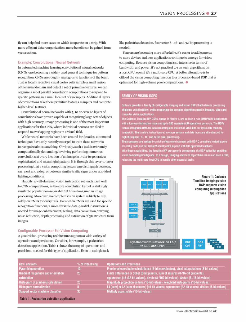
FAMILY OF VISION DSPS
Cadence provides a family of configurable imaging and vision DSPs that balances processing
efficiency with flexibility, whilst supporting the complex algorithms used in imaging, video and
computer vision applications.
The Cadence Tensilica IVP DSPs, shown in Figure 1, are built on a rich SIMD/VLIW architecture
with a four-way instruction issue and up to 200 separate ALU operations per cycle. The DSPs
feature integrated DMA for data streaming and more than 2000 bits per cycle data memory
bandwidth. The family’s instruction set, memory system and data types are all optimized for
high-throughput, 8-, 16- and 32-bit pixel processing.
The processors are backed by a rich software environment with DSP C compilers featuring zero
assembly code and full OpenCV and OpenVX support with 800 optimized functions.
With these capabilities, the Tensilica IVP processor is an example of a DSP suited for enabling
vision computing intelligence. In a design, imaging and video algorithms can run on such a DSP,
releasing the multi-core host CPU to handle other essential tasks.
Table 1: Pedestrian detection application
Figure 1: Cadence Tensilica imaging/vision
DSP supports vision computing intelligence
applications
28 HMI
April 2016
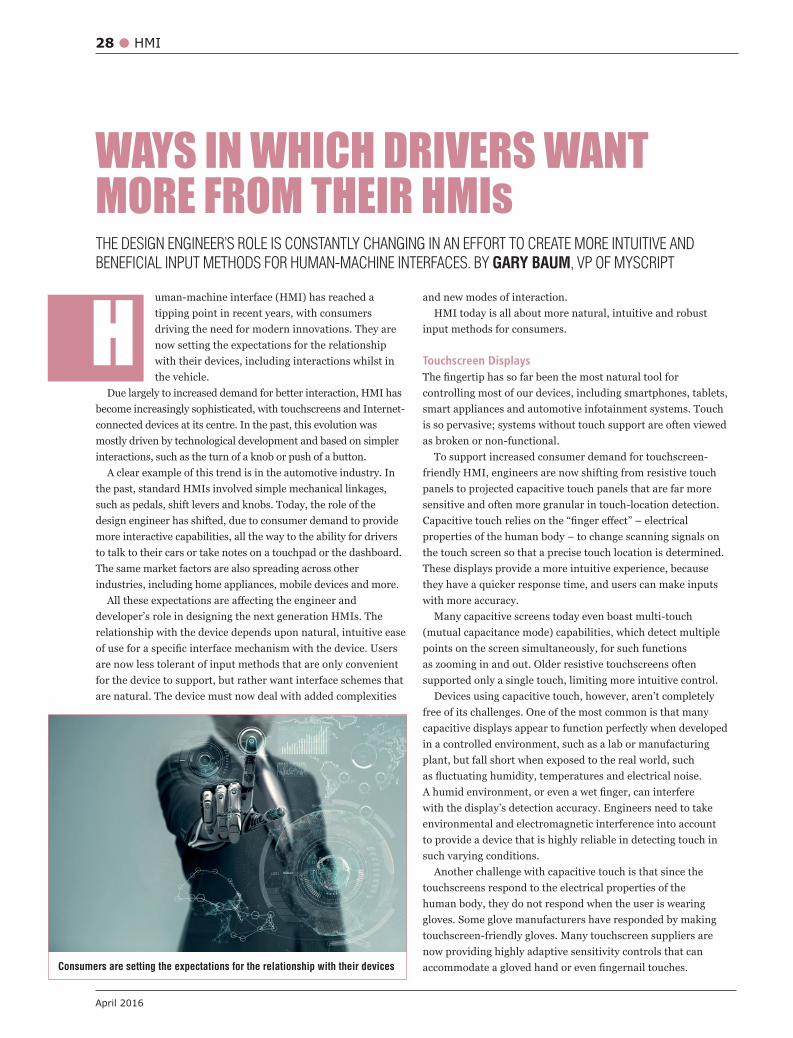
uman-machine interface (HMI) has reached a tipping point in recent years, with consumers driving the need for modern innovations. They are now setting the expectations for the relationship with their devices, including interactions whilst in the vehicle.
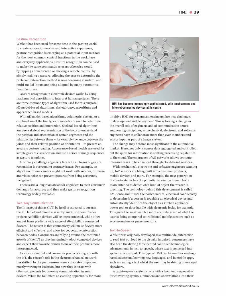
Due largely to increased demand for better interaction, HMI has become increasingly sophisticated, with touchscreens and Internet-connected devices at its centre. In the past, this evolution was mostly driven by technological development and based on simpler interactions, such as the turn of a knob or push of a button.
A clear example of this trend is in the automotive industry. In the past, standard HMIs involved simple mechanical linkages, such as pedals, shift levers and knobs. Today, the role of the design engineer has shifted, due to consumer demand to provide more interactive capabilities, all the way to the ability for drivers to talk to their cars or take notes on a touchpad or the dashboard. The same market factors are also spreading across other industries, including home appliances, mobile devices and more.
developer’s role in designing the next generation HMIs. The relationship with the device depends upon natural, intuitive ease
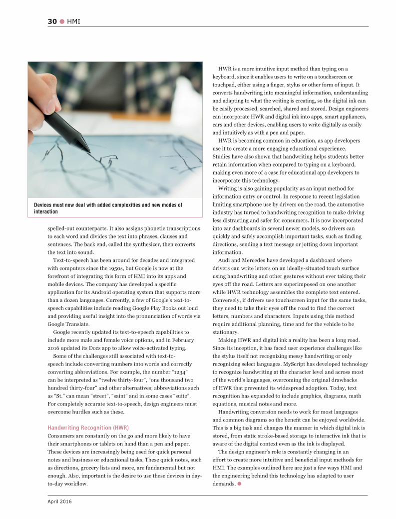
are now less tolerant of input methods that are only convenient for the device to support, but rather want interface schemes that are natural. The device must now deal with added complexities
WAYS IN WHICH DRIVERS WANT MORE FROM THEIR HMIs
Hand new modes of interaction.
HMI today is all about more natural, intuitive and robust input methods for consumers.
Touchscreen Displays
controlling most of our devices, including smartphones, tablets, smart appliances and automotive infotainment systems. Touch is so pervasive; systems without touch support are often viewed as broken or non-functional.
To support increased consumer demand for touchscreen-friendly HMI, engineers are now shifting from resistive touch panels to projected capacitive touch panels that are far more sensitive and often more granular in touch-location detection.
the touch screen so that a precise touch location is determined. These displays provide a more intuitive experience, because they have a quicker response time, and users can make inputs with more accuracy.
Many capacitive screens today even boast multi-touch (mutual capacitance mode) capabilities, which detect multiple points on the screen simultaneously, for such functions as zooming in and out. Older resistive touchscreens often supported only a single touch, limiting more intuitive control.
Devices using capacitive touch, however, aren’t completely free of its challenges. One of the most common is that many capacitive displays appear to function perfectly when developed in a controlled environment, such as a lab or manufacturing plant, but fall short when exposed to the real world, such
with the display’s detection accuracy. Engineers need to take environmental and electromagnetic interference into account to provide a device that is highly reliable in detecting touch in such varying conditions.
Another challenge with capacitive touch is that since the touchscreens respond to the electrical properties of the human body, they do not respond when the user is wearing gloves. Some glove manufacturers have responded by making touchscreen-friendly gloves. Many touchscreen suppliers are now providing highly adaptive sensitivity controls that can
Consumers are setting the expectations for the relationship with their devices
THE DESIGN ENGINEER’S ROLE IS CONSTANTLY CHANGING IN AN EFFORT TO CREATE MORE INTUITIVE AND
BENEFICIAL INPUT METHODS FOR HUMAN-MACHINE INTERFACES. BY GARY BAUM, VP OF MYSCRIPT
www.electronicsworld.co.uk
HMI 29
Gesture RecognitionWhile it has been used for some time in the gaming world to create a more immersive and interactive experience, gesture recognition is emerging as a potential input method for the most common control functions in the workplace and everyday applications. Gesture recognition can be used to make the same commands as users otherwise would by tapping a touchscreen or clicking a remote control, by simply making a gesture. Allowing the user to determine the preferred interaction method is now becoming standard, and multi-modal inputs are being adopted by many automotive manufacturers.
Gesture recognition in electronic devices works by using mathematical algorithms to interpret human gestures. There are three common types of algorithm used for this purpose: 3D model-based algorithms, skeletal-based algorithms and appearance-based models.
With 3D model-based algorithms, volumetric, skeletal or a combination of the two types of models are used to determine relative position and interaction. Skeletal-based algorithms analyze a skeletal representation of the body to understand the position and orientation of certain segments and the
accurate gesture reading. Appearance-based models are used for
as gesture templates.A primary challenge engineers face with all forms of gesture
recognition is overcoming accuracy issues. For example, an algorithm for one camera might not work with another, or image and video noise can prevent gestures from being accurately recognized.
There’s still a long road ahead for engineers to meet consumer demands for accuracy and then make gesture-recognition technology widely available.
Two-Way CommunicationThe Internet of things (IoT) by itself is expected to surpass the PC, tablet and phone market by 2017. Business Insider projects 50 billion devices will be interconnected, while other
devices. The reason is that connectivity will make devices more
between nodes. Consumers are rallying around the continued growth of the IoT as they increasingly adopt connected devices and expect their favorite brands to make their products more interconnected.
As more industrial and consumer products integrate with the IoT, the sensor’s role in the electromechanical network has shifted. In the past, sensors were a discrete component mostly working in isolation, but now they interact with other components for two-way communication in smart
intuitive HMI for consumers, engineers face new challenges in development and deployment. This is forcing a change in the overall role of engineers and of communication across engineering disciplines, as mechanical, electronic and software engineers have to collaborate more than ever to understand sensor input as part of a larger system.
market. Here, not only is sensor data aggregated and controlled, but the quest for information is shifting processing capabilities to the cloud. The emergence of 5G networks allows compute-intensive tasks to be enhanced through cloud-based services.
With mechanical, electronic and software engineers teaming up, IoT sensors are being built into consumer products, mobile devices and more. For example, the next generation of smartwatches has the potential to use the human body as an antenna to detect what kind of object the wearer is touching. The technology behind this development is called EM-Sense and it uses the body’s natural electrical conductivity to determine if a person is touching an electrical device and automatically identifies the object as a kitchen appliance, power tool or door handle with electronic locks, for example. This gives the smartwatch a more accurate grasp of what the user is doing compared to traditional mobile sensors such as accelerometers or pulse monitors.
Text-To-SpeechWhile it was originally developed as a multimodal interaction to read text out loud to the visually impaired, consumers have also been the driving force behind continued technological advancements in text-to-speech, where text is converted into spoken voice output. This type of HMI can be used for reading-based education, learning new languages, and in mobile apps, such as reading a text whilst the user may be driving or engaged elsewhere.
A text-to-speech system starts with a front end responsible for converting symbols, numbers and abbreviations into their
HMI has become increasingly sophisticated, with touchscreens and Internet-connected devices at its centre
HWR is a more intuitive input method than typing on a keyboard, since it enables users to write on a touchscreen or
converts handwriting into meaningful information, understanding and adapting to what the writing is creating, so the digital ink can be easily processed, searched, shared and stored. Design engineers can incorporate HWR and digital ink into apps, smart appliances, cars and other devices, enabling users to write digitally as easily and intuitively as with a pen and paper.
HWR is becoming common in education, as app developers use it to create a more engaging educational experience. Studies have also shown that handwriting helps students better retain information when compared to typing on a keyboard, making even more of a case for educational app developers to incorporate this technology.
Writing is also gaining popularity as an input method for information entry or control. In response to recent legislation limiting smartphone use by drivers on the road, the automotive industry has turned to handwriting recognition to make driving less distracting and safer for consumers. It is now incorporated into car dashboards in several newer models, so drivers can
directions, sending a text message or jotting down important information.
Audi and Mercedes have developed a dashboard where drivers can write letters on an ideally-situated touch surface using handwriting and other gestures without ever taking their eyes off the road. Letters are superimposed on one another while HWR technology assembles the complete text entered. Conversely, if drivers use touchscreen input for the same tasks, they need to take their eyes off the road to find the correct letters, numbers and characters. Inputs using this method require additional planning, time and for the vehicle to be stationary.
Making HWR and digital ink a reality has been a long road. Since its inception, it has faced user experience challenges like the stylus itself not recognizing messy handwriting or only recognizing select languages. MyScript has developed technology to recognize handwriting at the character level and across most of the world’s languages, overcoming the original drawbacks of HWR that prevented its widespread adoption. Today, text recognition has expanded to include graphics, diagrams, math equations, musical notes and more.
Handwriting conversion needs to work for most languages
This is a big task and changes the manner in which digital ink is stored, from static stroke-based storage to interactive ink that is aware of the digital context even as the ink is displayed.
The design engineer’s role is constantly changing in an
HMI. The examples outlined here are just a few ways HMI and the engineering behind this technology has adapted to user demands. g
30 HMI
April 2016
spelled-out counterparts. It also assigns phonetic transcriptions to each word and divides the text into phrases, clauses and sentences. The back end, called the synthesizer, then converts the text into sound.
Text-to-speech has been around for decades and integrated with computers since the 1950s, but Google is now at the forefront of integrating this form of HMI into its apps and
application for its Android operating system that supports more than a dozen languages. Currently, a few of Google’s text-to-speech capabilities include reading Google Play Books out loud and providing useful insight into the pronunciation of words via Google Translate.
Google recently updated its text-to-speech capabilities to include more male and female voice options, and in February 2016 updated its Docs app to allow voice-activated typing.
Some of the challenges still associated with text-to-speech include converting numbers into words and correctly
For completely accurate text-to-speech, design engineers must overcome hurdles such as these.
Handwriting Recognition (HWR)Consumers are constantly on the go and more likely to have their smartphones or tablets on hand than a pen and paper. These devices are increasingly being used for quick personal notes and business or educational tasks. These quick notes, such as directions, grocery lists and more, are fundamental but not enough. Also, important is the desire to use these devices in day-
Devices must now deal with added complexities and new modes of interaction

32 ELECTRIC CARS
April 2016
ybrid electric vehicles are widely considered to be green vehicles with fewer polluting emissions. They offer advantages such as energy saving and clean running, with research showing that they offer energy savings of over 30% and produce 15% CO2 emissions than traditional vehicles.
In addition, traditional vehicle driving systems consist of many power-train components that do not exist in hybrid vehicles, making them simpler and more efficient. Hybrid vehicle motors can be controlled directly, so it is possible to design electronic control systems such as ABS (anti-lock braking), ESP (vehicle stability), TCS (traction control) and others. However, the electronic control system in electric vehicles is implemented based on original engine models, since drive motors are mounted directly on the drive axles.
Although this method reduces the design cycle and lowers costs, it doesn’t completely exploit the advantages
H
Figure 2: Schematic of the RT3102 instrument’s internal components
of electric vehicles. Furthermore, some hybrid vehicles use independent control of each of the four wheels, which makes coordinated control between motors more complicated. In this case, the measurement of a hybrid electric vehicle’s stability is even more crucial and necessary for vehicle safety.
Statistics by German car-maker Audi show that traffic accidents at speeds of 80km/h and above are caused by some 40% of the vehicles losing stability. Faster than 160km/h, almost all accidents are related to instability.
Better ControlVehicle handling stability can be improved by controlling the vehicle’s yaw motion. Sideslip angle and yaw rate are two most important stability parameters. Sideslip angle is the angle between the longitudinal axis of the automobile and its direction. But, the sideslip angle can’t be
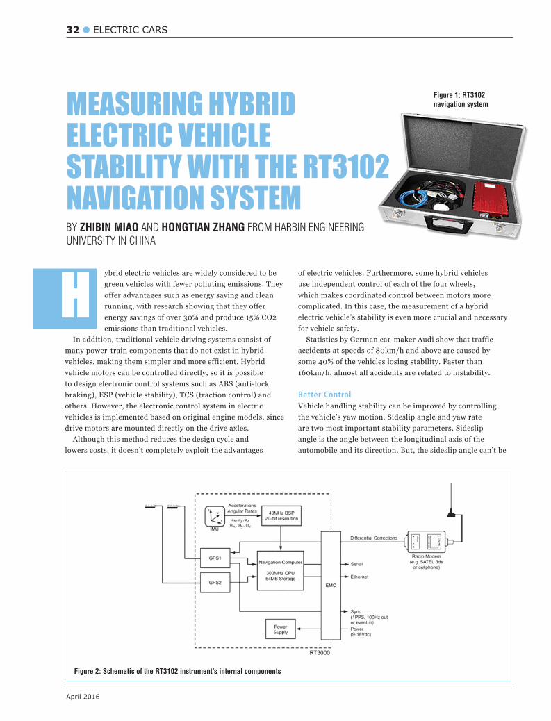
Figure 1: RT3102 navigation system
BY ZHIBIN MIAO AND HONGTIAN ZHANG FROM HARBIN ENGINEERING
UNIVERSITY IN CHINA
MEASURING HYBRID ELECTRIC VEHICLE STABILITY WITH THE RT3102 NAVIGATION SYSTEM
www.electronicsworld.co.uk
ELECTRIC CARS 33
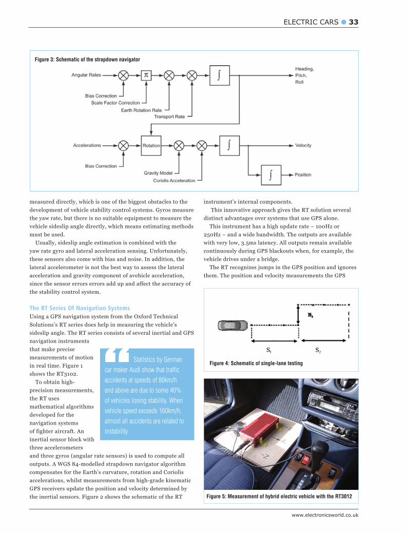
Figure 3: Schematic of the strapdown navigator
measured directly, which is one of the biggest obstacles to the development of vehicle stability control systems. Gyros measure the yaw rate, but there is no suitable equipment to measure the vehicle sideslip angle directly, which means estimating methods must be used.
Usually, sideslip angle estimation is combined with the yaw rate gyro and lateral acceleration sensing. Unfortunately, these sensors also come with bias and noise. In addition, the lateral accelerometer is not the best way to assess the lateral acceleration and gravity component of avehicle acceleration, since the sensor errors errors add up and affect the accuracy of the stability control system.
The RT Series Of Navigation SystemsUsing a GPS navigation system from the Oxford Technical Solutions’s RT series does help in measuring the vehicle’s sideslip angle. The RT series consists of several inertial and GPS navigation instruments that make precise measurements of motion in real time. Figure 1 shows the RT3102.
To obtain high-precision measurements, the RT uses mathematical algorithms developed for the navigation systems of fighter aircraft. An inertial sensor block with three accelerometers and three gyros (angular rate sensors) is used to compute all outputs. A WGS 84-modelled strapdown navigator algorithm compensates for the Earth’s curvature, rotation and Coriolis accelerations, whilst measurements from high-grade kinematic GPS receivers update the position and velocity determined by the inertial sensors. Figure 2 shows the schematic of the RT
instrument’s internal components. This innovative approach gives the RT solution several
distinct advantages over systems that use GPS alone.
with very low, 3.5ms latency. All outputs remain available continuously during GPS blackouts when, for example, the vehicle drives under a bridge.
them. The position and velocity measurements the GPS
“ Statistics by German
car maker Audi show that traffic
accidents at speeds of 80km/h
and above are due to some 40%
of vehicles losing stability. When
vehicle speed exceeds 160km/h,
almost all accidents are related to
instability
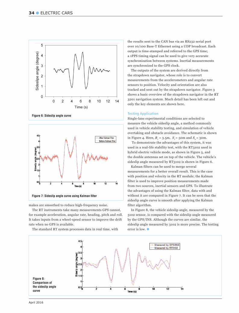
Figure 4: Schematic of single-lane testing
Figure 5: Measurement of hybrid electric vehicle with the RT3012
34 ELECTRIC CARS
April 2016
makes are smoothed to reduce high-frequency noise. The RT instruments take many measurements GPS cannot,
for example acceleration, angular rate, heading, pitch and roll. It takes inputs from a wheel-speed sensor to improve the drift rate when no GPS is available.
The standard RT system processes data in real time, with
the results sent to the CAN bus via an RS232 serial port over 10/100 Base-T Ethernet using a UDP broadcast. Each output is time-stamped and referred to the GPS time; a 1PPS timing signal can be used to give very accurate
The outputs of the system are derived directly from the strapdown navigator, whose role is to convert measurements from the accelerometers and angular rate sensors to position. Velocity and orientation are also tracked and sent out by the strapdown navigator. Figure 3 shows a basic overview of the strapdown navigator in the RT 3201 navigation system. Much detail has been left out and only the key elements are shown here.
Testing Application Single-lane experimental conditions are selected to measure the vehicle sideslip angle, a method commonly used in vehicle stability testing, and simulation of vehicle overtaking and obstacle avoidance. The schematic is shown in Figure 4. Here, B1 = 3.5m, S1 = 50m and S2 = 30m.
To demonstrate the advantages of this system, it was used in a real-life stability test, with the RT3102 used in hybrid electric vehicle mode, as shown in Figure 5, and the double antennas set on top of the vehicle. The vehicle’s sideslip angle measured by RT3102 is shown in Figure 6.
Kalman filters can be used to merge several measurements for a better overall result. This is the case with position and velocity in the RT module; the Kalman filter is used to improve position measurements made from two sources, inertial sensors and GPS. To illustrate the advantages of using the Kalman filter, data with and without it are compared in Figure 7. It can be seen that the sideslip angle curve is smooth after applying the Kalman filter algorithm.
In Figure 8, the vehicle sideslip angle, measured by the 3102 sensor, is compared with the sideslip angle measured by the GPS/INS. Although the curves are similar, the sideslip angle measured by 3102 is more precise. The testing error is low.
Figure 6: Sideslip angle curve
Figure 7: Sideslip angle curve using Kalman filter
Figure 8: Comparison of the sideslip angle curve

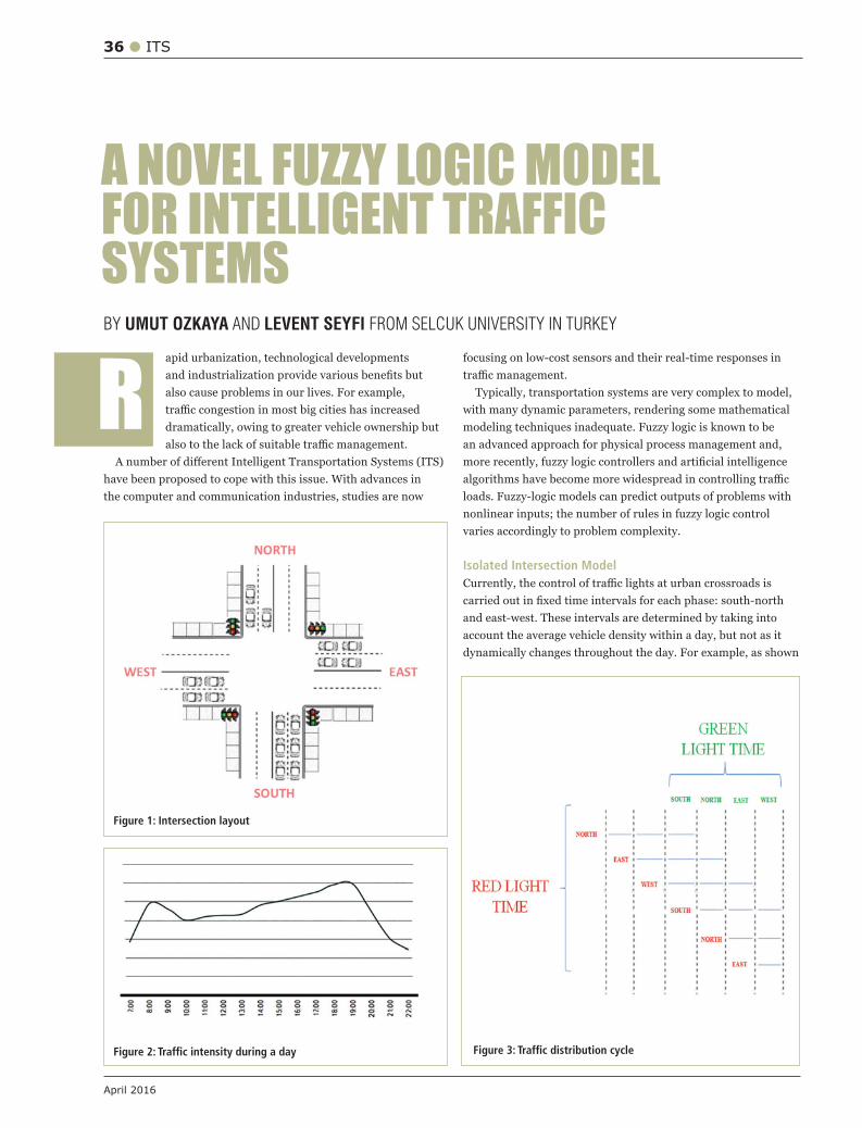
36 ITS
April 2016
apid urbanization, technological developments
also cause problems in our lives. For example,
dramatically, owing to greater vehicle ownership but
have been proposed to cope with this issue. With advances in the computer and communication industries, studies are now
BY UMUT OZKAYA AND LEVENT SEYFI FROM SELCUK UNIVERSITY IN TURKEY
Rfocusing on low-cost sensors and their real-time responses in
with many dynamic parameters, rendering some mathematical modeling techniques inadequate. Fuzzy logic is known to be an advanced approach for physical process management and,
loads. Fuzzy-logic models can predict outputs of problems with nonlinear inputs; the number of rules in fuzzy logic control varies accordingly to problem complexity.
Isolated Intersection Model
account the average vehicle density within a day, but not as it dynamically changes throughout the day. For example, as shown
A NOVEL FUZZY LOGIC MODEL FOR INTELLIGENT TRAFFIC SYSTEMS
Figure 2: Traffic intensity during a day
Figure 1: Intersection layout
Figure 3: Traffic distribution cycle
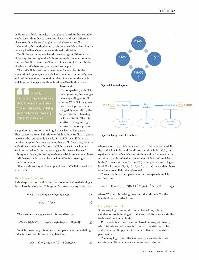
www.electronicsworld.co.uk
ITS 37
Generally, this method aims to minimize vehicle delays, but it’s
of the day. For example, the daily commute is the most common
conventional system, every cycle has a constant amount of green and red time, making the total number of cycles per day stable, which never changes even though vehicle distribution in each
phase might.
some cycles may have longer
time in each phase can be changed dynamically by the fuzzy controller, changing
duration of the green light in three of the four phases
is equal to the duration of red light times for the last phase.
are intertwined and they may change with the so called self-subsequent phases, for example when a vehicle arrives at a phase.
All these criteria have to be considered before creating a simulation model.
crossroads.
State Space EquationsA single-phase intersection must be modelled before designing a
Vehicle queue length is an important parameter in modelling a
where i = 0, 1, 2, 3… M and n = 0, 1, 2, 3… N-1 are sequentially Q
i(n) and
qi(n) are number of vehicles at nth time and in ith queue in the
nth time. di(n)
in the ith queue at the nth time. S(n) is the phase state at logic (S
1, S
2, S
3, S
4) = (0, 0, 0, 1) means that phase
four has a green light, the others red.
length of the discretized time.
Fuzzy Logic Control
to those of the human brain.Fuzzy logic is a control method based on fuzzy set theory,
which translates real values into human linguistic variables
parameters.
certainty, multi parameters and non-linear behaviour.
Figure 4: Phase diagram
Figure 5: Fuzzy control structure
“ Typically,
transportation systems are very
complex to model, with many
dynamic parameters, rendering
some mathematical modeling
techniques inadequate
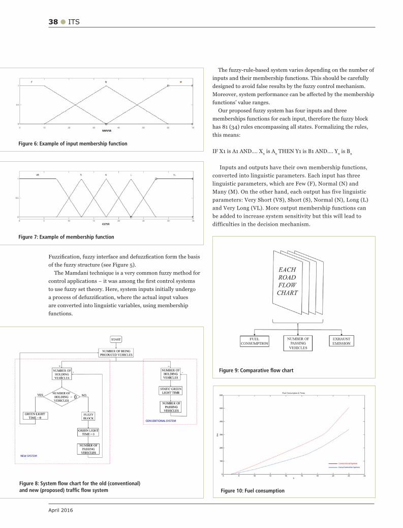
38 ITS
April 2016
to use fuzzy set theory. Here, system inputs initially undergo
are converted into linguistic variables, using membership functions.
designed to avoid false results by the fuzzy control mechanism.
functions’ value ranges. Our proposed fuzzy system has four inputs and three
memberships functions for each input, therefore the fuzzy block
n is An n n
be added to increase system sensitivity but this will lead to difficulties in the decision mechanism.
Figure 6: Example of input membership function
Figure 7: Example of membership function
Figure 9: Comparative flow chart
Figure 10: Fuel consumptionFigure 8: System flow chart for the old (conventional) and new (proposed) traffic flow system
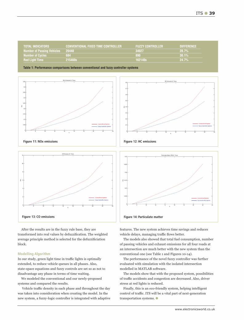
www.electronicsworld.co.uk
ITS 39
After the results are in the fuzzy rule base, they are
block.
Modelling Algorithm
extended, to reduce vehicle queues in all phases. Also, state-space equations and fuzzy controls are set so as not to disadvantage any phase in terms of time waiting.
We modeled the conventional and our newly-proposed systems and compared the results.
new system, a fuzzy-logic controller is integrated with adaptive
of passing vehicles and exhaust emissions for all four roads at an intersection are much better with the new system than the
evaluated with simulation with the isolated intersection
stress at red lights is reduced. Finally, this is an eco-friendly system, helping intelligent
transportation systems.
TOTAL INDICATORS CONVENTIONAL FIXED TIME CONTROLLER FUZZY CONTROLLER DIFFERENCE
Number of Passing Vehicles 26440 34027 28.7%
Number of Cycles 684 890 30.1%
Red Light Time 215460s 162140s 24.7%
Table 1: Performance comparisons between conventional and fuzzy controller systems
Figure 11: NOx emissions Figure 12: HC emissions
Figure 13: CO emissions Figure 14: Particulate matter

40 MOTOR CONTROL
April 2016
he first electric motor was invented by William Sturgeon in 1832, whereas the first commercially successful electric motor was created in 1873.
Today, electric motors are found in a variety of applications, including domestic, industrial, mining, agriculture, transportation and others.
They can be used in elevators and lifts, kitchen machines, wristwatches, mobile phones (to vibrate instead of ring), scanners, printers, plotters, robots and others, as suggested in Figure 1.
Motors’ flexibility and wide variety mean they can be matched to almost any kind of application.
Motor Types Depending on the power supply, motors can be divided into two groups: AC (alternate current), run by high voltage, and DC motors (direct current), run by rechargeable batteries and thus suitable for portable applications.
There are two main types of DC motors: brush and brushless. The brush DC motor uses a rotor with stationary magnets, whereas the brushless ones use rotating permanent magnets.
Then there are:1. Stepper Motors, which are brushless, and rotate in
multiple steps. The stepper can move and hold at one
STOJCE DIMOV ILCEV FROM DURBAN UNIVERSITY OF TECHNOLOGY (DUT) IN SOUTH AFRICA GIVES A AN
OVERVIEW OF DIFFERENT TYPES OF MOTORS AND HOW BEST TO CONTROL THEM
Tof these steps without a feedback sensor. Stepper motors are used to position the heads in floppy disk drives, and in plotters, CD ROMs and scanners among others.
2. Servo Motors. These are used in servomechanisms, a device relying on error sensing to improve machine performance. In specific applications and high-torque requirements, these motors can produce 8,000-70,000RPM.
Motor ControlEnergy efficiency, mobility and security are important challenges facing modern society. Motor-control solutions can address all these needs, providing outstanding reliability, excellent quality and leading-edge innovations. Thus, it’s everyone’s goal to consistently improve motors’ computing performance, switching frequency, figure of merit, accuracy, quality and reliability, to name just a few of their many technical parameters.
As new product generations are released, each device becomes a benchmark in its own category. But the real beauty lies in combining these individual devices and their strengths to create different motor control systems able to set new standards in energy efficiency, dynamic behaviour, robustness and longevity.
It is also very important to harness the benefits of efficient semiconductor solutions for electric motor control and drive applications.
AC MotorsAC motors are much more prevalent than DC motors since they offer several advantages. To match the choice of an AC motor to the application, it is essential to know the different types.
The first type is the induction motor, also known as asynchronous. Figure 2 shows a domestic low-power AC motor (left) and an industrial high-power AC motor (right).
Figure 3 shows a simplified drawing of an induction motor (left) and construction of its cage with a shorted rotor (right). Such motors are used for kitchen aspirators, low-pressure water pumps, air conditioners, hair dryers, mixers, vacuum cleaners, fans and other domestic appliances where there’s no need for high torque. They are self-starting, but because of their relative low power and speed, control is not used.
AC motors are categorized as single-phase or three-phase AC
BASICS OF ELECTRIC MOTOR CONTROL
Figure 1: The motor’s versatility
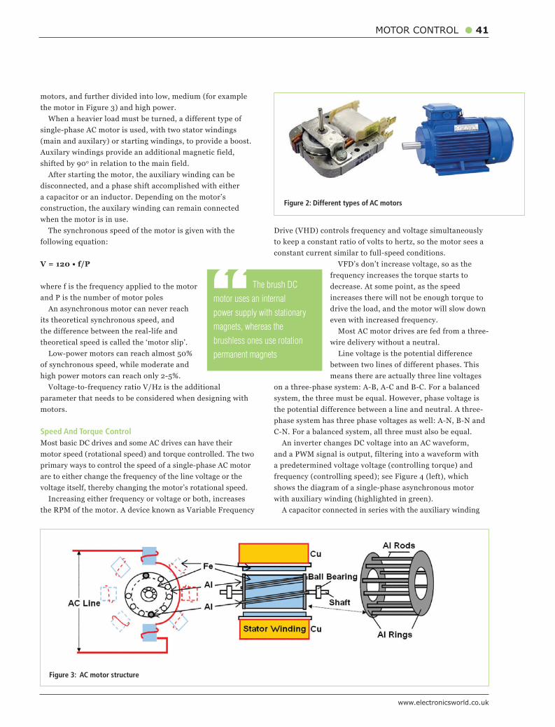
www.electronicsworld.co.uk
MOTOR CONTROL 41
motors, and further divided into low, medium (for example the motor in Figure 3) and high power.
When a heavier load must be turned, a different type of single-phase AC motor is used, with two stator windings (main and auxilary) or starting windings, to provide a boost. Auxilary windings provide an additional magnetic field, shifted by 900 in relation to the main field.
After starting the motor, the auxiliary winding can be disconnected, and a phase shift accomplished with either a capacitor or an inductor. Depending on the motor’s construction, the auxilary winding can remain connected when the motor is in use.
The synchronous speed of the motor is given with the following equation:
V = 120 • f/P
where f is the frequency applied to the motor and P is the number of motor poles
An asynchronous motor can never reach its theoretical synchronous speed, and the difference between the real-life and theoretical speed is called the ‘motor slip’.
Low-power motors can reach almost 50% of synchronous speed, while moderate and high power motors can reach only 2-5%.
Voltage-to-frequency ratio V/Hz is the additional parameter that needs to be considered when designing with motors.
Speed And Torque ControlMost basic DC drives and some AC drives can have their motor speed (rotational speed) and torque controlled. The two primary ways to control the speed of a single-phase AC motor are to either change the frequency of the line voltage or the voltage itself, thereby changing the motor’s rotational speed.
Increasing either frequency or voltage or both, increases the RPM of the motor. A device known as Variable Frequency
Drive (VHD) controls frequency and voltage simultaneously to keep a constant ratio of volts to hertz, so the motor sees a constant current similar to full-speed conditions.
VFD’s don’t increase voltage, so as the frequency increases the torque starts to decrease. At some point, as the speed increases there will not be enough torque to drive the load, and the motor will slow down even with increased frequency.
Most AC motor drives are fed from a three-wire delivery without a neutral.
Line voltage is the potential difference between two lines of different phases. This means there are actually three line voltages
on a three-phase system: A-B, A-C and B-C. For a balanced system, the three must be equal. However, phase voltage is the potential difference between a line and neutral. A three-phase system has three phase voltages as well: A-N, B-N and C-N. For a balanced system, all three must also be equal.
An inverter changes DC voltage into an AC waveform, and a PWM signal is output, filtering into a waveform with a predetermined voltage voltage (controlling torque) and frequency (controlling speed); see Figure 4 (left), which shows the diagram of a single-phase asynchronous motor with auxiliary winding (highlighted in green).
A capacitor connected in series with the auxiliary winding
“ The brush DC
motor uses an internal
power supply with stationary
magnets, whereas the
brushless ones use rotation
permanent magnets
Figure 2: Different types of AC motors
Figure 3: AC motor structure
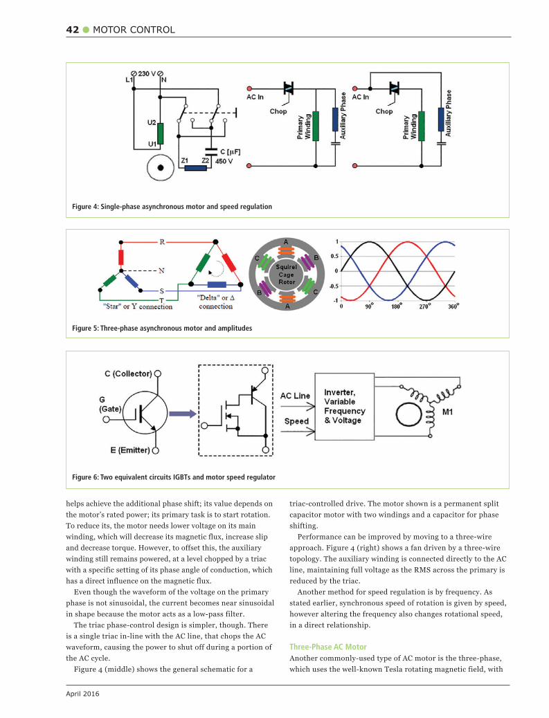
42 MOTOR CONTROL
April 2016
helps achieve the additional phase shift; its value depends on the motor’s rated power; its primary task is to start rotation. To reduce its, the motor needs lower voltage on its main winding, which will decrease its magnetic flux, increase slip and decrease torque. However, to offset this, the auxiliary winding still remains powered, at a level chopped by a triac with a specific setting of its phase angle of conduction, which has a direct influence on the magnetic flux.
Even though the waveform of the voltage on the primary phase is not sinusoidal, the current becomes near sinusoidal in shape because the motor acts as a low-pass filter.
The triac phase-control design is simpler, though. There is a single triac in-line with the AC line, that chops the AC waveform, causing the power to shut off during a portion of the AC cycle.
Figure 4 (middle) shows the general schematic for a
triac-controlled drive. The motor shown is a permanent split capacitor motor with two windings and a capacitor for phase shifting.
Performance can be improved by moving to a three-wire approach. Figure 4 (right) shows a fan driven by a three-wire topology. The auxiliary winding is connected directly to the AC line, maintaining full voltage as the RMS across the primary is reduced by the triac.
Another method for speed regulation is by frequency. As stated earlier, synchronous speed of rotation is given by speed, however altering the frequency also changes rotational speed, in a direct relationship.
Three-Phase AC MotorAnother commonly-used type of AC motor is the three-phase, which uses the well-known Tesla rotating magnetic field, with
Figure 4: Single-phase asynchronous motor and speed regulation
Figure 5: Three-phase asynchronous motor and amplitudes
Figure 6: Two equivalent circuits IGBTs and motor speed regulator
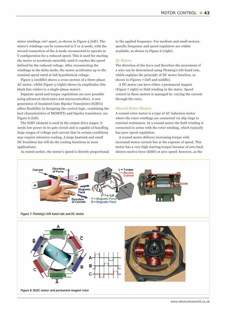
www.electronicsworld.co.uk
MOTOR CONTROL 43
stator windings 120o apart, as shown in Figure 5 (left). The
Y configuration for a reduced speed. This is used for starting the motor to accelerate smoothly until it reaches the speed defined by the reduced voltage. After reconnecting the windings in the delta mode, the motor accelerates up to the nominal speed rated at full hypothetical voltage. Figure 5 (middle) shows a cross-section of a three-phase AC motor, whilst Figure 5 (right) shows its amplitudes (the black line relates to a single-phase motor).
Separate speed and torque regulations are now possible using advanced electronics and microcontrollers. A new generation of Insulated Gate Bipolar Transistors (IGBTs) offers flexibility in designing the control logic, combining the best characteristics of MOSFETs and bipolar transistors; see Figure 6 (left).
The IGBT element is used in the output drive stages; it needs low power in its gate circuit and is capable of handling large ranges of voltage and current that in certain conditions may require intensive cooling. A large heatsink and small DC brushless fan will do the cooling functions in most applications.
As stated earlier, the motor’s speed is directly proportional
to the applied frequency. For medium and small motors, specific frequency and speed regulators are widely available, as shown in Figure 6 (right).
DC MotorsThe direction of the force and therefore the movement of a wire can be determined using Fleming’s left-hand rule, which explains the principle of DC motor function, as shown in Figures 7 (left and middle).
A DC motor can have either a permanent magnet (Figure 7 right) or field winding in the stator. Speed control in these motors is managed by varying the current through the rotor.
Wound Rotor MotorsA wound-rotor motor is a type of AC induction motor where the rotor windings are connected via slip rings to external resistances. In a wound motor the field winding is connected in series with the rotor winding, which typically has poor speed regulation.
A wound motor delivers increasing torque with increased motor current but at the expense of speed. This motor has a very high starting-torque because of zero back electro-motive force (EMF) at zero speed; however, as the
Figure 7: Fleming’s left hand rule and DC motor
Figure 8: BLDC motor and permanent magnet rotor
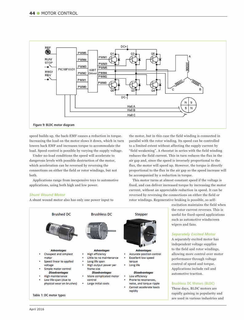
44 MOTOR CONTROL
April 2016
speed builds up, the back-EMF causes a reduction in torque. Increasing the load on the motor slows it down, which in turn lowers back EMF and increases torque to accommodate the load. Speed control is possible by varying the supply voltage.
Under no-load conditions the speed will accelerate to dangerous levels with possible destruction of the motor, which acceleration can be reversed by reversing the connections on either the field or rotor windings, but not both.
Applications range from inexpensive toys to automotive applications, using both high and low power.
Shunt Wound MotorA shunt wound motor also has only one power input to
the motor, but in this case the field winding is connected in parallel with the rotor winding. Its speed can be controlled to a limited extent without affecting the supply current by “field weakening”. A rheostat in series with the field winding reduces the field current. This in turn reduces the flux in the air gap and, since the speed is inversely proportional to the flux, the motor will speed up. However, the torque is directly proportional to the flux in the air gap so the speed increase will be accompanied by a reduction in torque.
This motor turns at almost constant speed if the voltage is fixed, and can deliver increased torque by increasing the motor current, without an appreciable reduction in speed. It can be reversed by reversing the connections on either the field or rotor windings. Regenerative braking is possible, so self-
excitation maintains the field when the rotor current reverses. This is useful for fixed-speed applications such as automotive windscreen wipers and fans.
Separately Excited MotorA separately excited motor has independent voltage supplies to the field and rotor windings, allowing more control over motor performance through voltage control of speed and torque. Applications include rail and automotive traction.
Brushless DC Motors (BLDC)These days, BLDC motors are rapidly gaining in popularity and are used in various industries and
Figure 9: BLDC motor diagram
Table 1: DC motor types
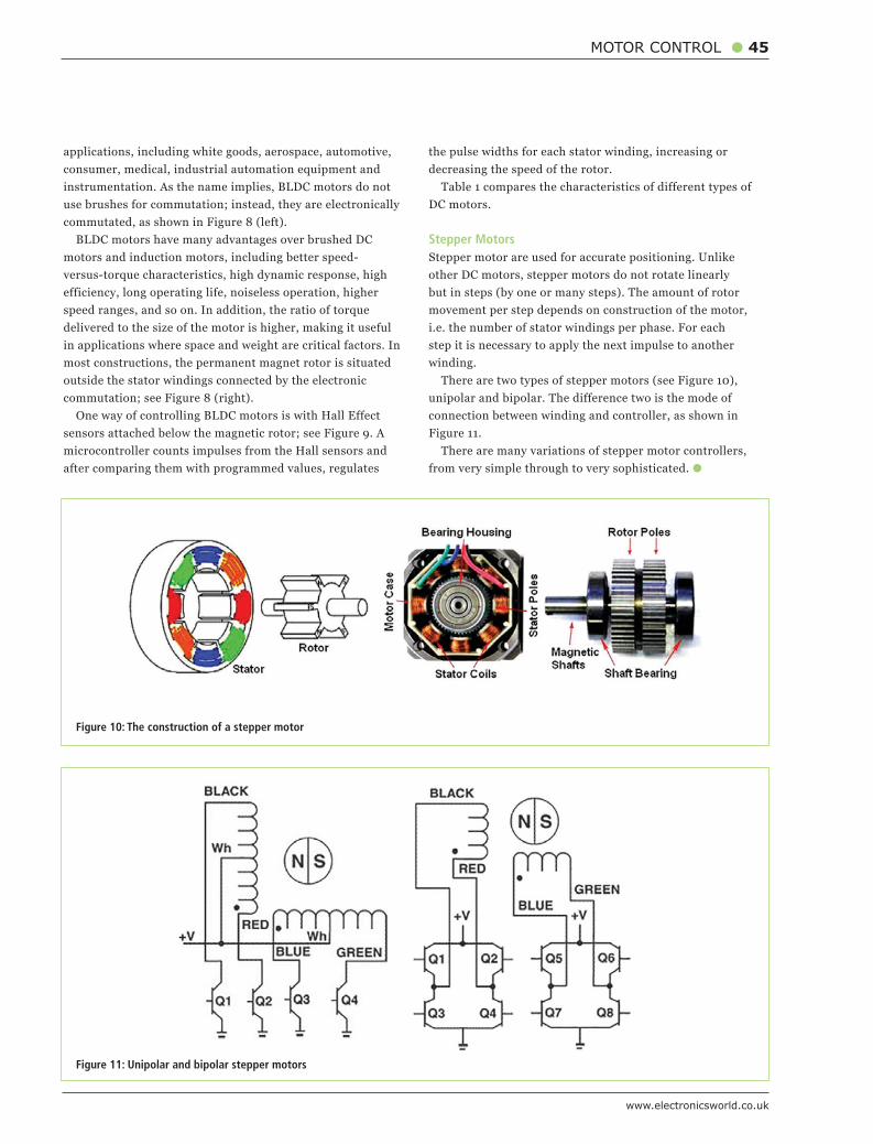
www.electronicsworld.co.uk
MOTOR CONTROL 45
applications, including white goods, aerospace, automotive, consumer, medical, industrial automation equipment and instrumentation. As the name implies, BLDC motors do not use brushes for commutation; instead, they are electronically commutated, as shown in Figure 8 (left).
BLDC motors have many advantages over brushed DC motors and induction motors, including better speed-versus-torque characteristics, high dynamic response, high efficiency, long operating life, noiseless operation, higher speed ranges, and so on. In addition, the ratio of torque delivered to the size of the motor is higher, making it useful in applications where space and weight are critical factors. In most constructions, the permanent magnet rotor is situated outside the stator windings connected by the electronic commutation; see Figure 8 (right).
One way of controlling BLDC motors is with Hall Effect sensors attached below the magnetic rotor; see Figure 9. A microcontroller counts impulses from the Hall sensors and after comparing them with programmed values, regulates
the pulse widths for each stator winding, increasing or decreasing the speed of the rotor.
Table 1 compares the characteristics of different types of DC motors.
Stepper MotorsStepper motor are used for accurate positioning. Unlike other DC motors, stepper motors do not rotate linearly but in steps (by one or many steps). The amount of rotor movement per step depends on construction of the motor, i.e. the number of stator windings per phase. For each step it is necessary to apply the next impulse to another winding.
There are two types of stepper motors (see Figure 10), unipolar and bipolar. The difference two is the mode of connection between winding and controller, as shown in Figure 11.
There are many variations of stepper motor controllers, from very simple through to very sophisticated.
Figure 10: The construction of a stepper motor
Figure 11: Unipolar and bipolar stepper motors
46 PRODUCTS
April 2016
ALLEGRO ANNOUNCES NEW DMOS MICROSTEPPING DRIVER Allegro MicroSystems Europe announced a new
integrated bipolar stepper motor driver IC with built-in
translator for easy operation. The A5984 is designed
to operate bipolar stepper motors from full-step up
to 1/32 step modes that are selectable by MSx logic
inputs.
This new device has an output drive capacity of
up to 40V and ±2A and operates with a single supply.
It is targeted at the office and industrial automation
markets with key applications to include: automatic
teller machines, point of sale and laser printers, 3D
printers, copiers, CCTV, cameras, sewing machines,
vending and robotics.
Allegro’s A5984 motor driver IC introduces a
proprietary Adaptive Percent Fast Decay (APFD)
algorithm to optimise the current waveform over
a wide range of stepper speeds and stepper motor
characteristics.
www.allegromicro.com
MOUSER NOW SHIPPING INDUSTRY’S SMALLEST IO-LINK DEVICE TRANSCEIVER Mouser Electronics is now stocking the MAX14827
transceiver from Maxim Integrated. As the industry’s
smallest dual-channel transceiver using IO-Link
point-to-point communication technology, the
MAX14827 transceiver allows designers incorporate
intelligent sensors with continuous diagnostics and
monitoring into Industry 4.0 or industrial Internet of
Things (IoT) applications.
The Maxim MAX14827 dual-channel transceiver
integrates the high-voltage functions commonly found
in industrial sensors, including drivers and regulators.
It features two ultra-low-power drivers with active
reverse-polarity protection to reduce downtime. It
also provides a selectable driver current (50mA to
250mA), supports supply voltages from 24-60V and
includes a micro transient voltage suppressor (TVS)
that increases voltage tolerance to provide transient
voltage protection.
www.mouser.com
PARTNERSHIP ACHIEVES ‘MOST AMBITIOUS’ CONNECTOR ASSEMBLY MACHINE Hi-rel connector maker Harwin and automation
technology supplier Festo have built one of the largest
assembly lines around, in response to Harwin’s
growing sales of the Gecko 1.25mm pitch connector
family.
Festo delivered a full range of pneumatics, PLCs,
drives, motors and electric axis that allowed Harwin
to select the best suited technology in each area of the
machine. The new assembly line also includes laser
marking and it can automatically assemble the full
range of Gecko products up to 50 contacts.
“It is our company philosophy to invest in the latest
equipment and pursue a drive towards automation.
As the Gecko range continues to grow with increasing
variants and design options we needed this new
machine,” said Paul McGuinness, Harwin’s Director
of Engineering.
www.harwin.co.uk
TEKTRONIX EXPANDS INNOVATIVE USB-BASED REAL-TIME SPECTRUM ANALYZER LINE-UP Tektronix has expanded its line of USB-based real-
time spectrum analyzers with four new higher-
performance models targeting design, spectrum
management, wireless transmitter installation
and maintenance applications. The new RSA500
and RSA600 series of analyzers offer frequency
coverage from 9kHz up to 7.5GHz with 40MHz
acquisition bandwidth, a measurement dynamic
range from -161dBm/Hz Displayed Average Noise
Level and up to +30dBm maximum input.
The analyzers use the design approach of
the very successful 6.2GHz RSA306 USB-based
real-time spectrum analyzer introduced last year,
offering even higher instrument performance
levels and analysis capabilities in two new
compact, affordable packages. www.tektronix.com
ROBUST CABLE ASSEMBLIES FOR HEAVY-DUTY APPLICATIONS Overmoulded cable assemblies are the
definitive choice for harsh and demanding
environments. They are widely used in
consumer and industrial environments as they
offer a variety of valuable benefits.
In consumer electronics, overmoulding
offers durability, protection from tampering and
safeguards against moisture ingress, making
it the finish of choice for I/O connections and
desktop and networking products. In industrial
applications, overmoulded cable assemblies
can be designed and manufactured to
withstand the specific demands of their working
environment, which is typically harsher.
All component parts of the outer cable
assembly are carefully designed to ensure they
are fit for purpose. www.gtk.co.uk
NEW MINIATURE QUARTZ CRYSTALS AND OSCILLATORS FROM GEYER ELECTRONIC Geyer Electronic has released its new micro
SMD RTC crystal – the KX-327VT, measuring
only 1.25mm x 1.05mm x 0.5mm.
Manufactured by a special, fully-automatic
production process, the crystal offers accurate
time measuring over a very long period. It has
an operating temperature of -40°C to +85°C,
standard tolerance of ±20ppm and is available
with load capacitances of 12.5pF or 7pF for
lower power consumption.
Geyer’s also offers the new VCTCXO KXO-81,
which measures just 2mm x 1.6mm x 0.7mm,
with a frequency tolerance of ±1.5ppm (±2.5ppm
25°C) and 1.5mA power consumption.
Also available as a TCXO, it is an ideal
component for W-LAN, ISM, NFT and wireless
modules.www.geyer-electronic.co.uk