Embed Size (px)
Citation preview
ReplacementStandard values, such as torques and certain adjustments,
If removed, the following parts should always be replaced
6
Parts Depending on their location.
When replacing parts, use HYUNDAI genuine parts.
of parts.
9. Specified oil or grease should be applied to the
AdjustmentUse gauges and testers to adjust correclty the parts to
standard values correctly
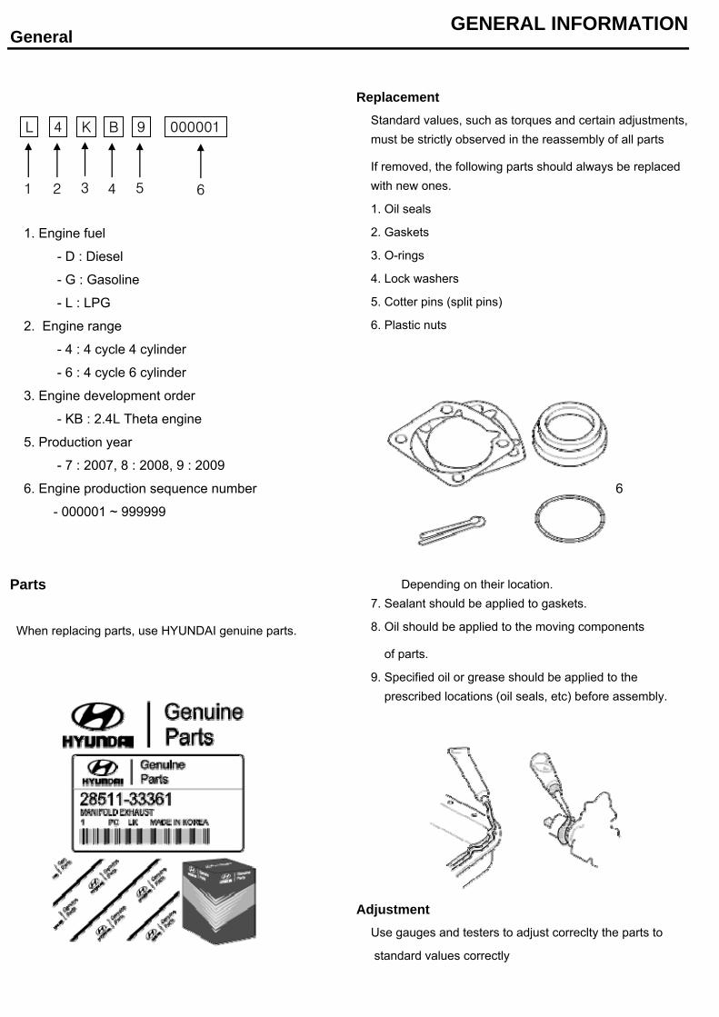
- 6 : 4 cycle 6 cylinder
- 000001 ~ 999999
prescribed locations (oil seals, etc) before assembly.
- KB : 2.4L Theta engine
5. Production year
- 7 : 2007, 8 : 2008, 9 : 2009
6. Engine production sequence number
GENERAL INFORMATIONGeneral
must be strictly observed in the reassembly of all parts
with new ones.
1. Oil seals
2. Gaskets
3. O-rings
- L : LPG
2. Engine range
- 4 : 4 cycle 4 cylinder
3. Engine development order
- G : Gasoline
1. Engine fuel
- D : Diesel4. Lock washers
5. Cotter pins (split pins)
6. Plastic nuts
8. Oil should be applied to the moving components
7. Sealant should be applied to gaskets.
4 K B 9L 000001
2 3 4 51 6
4 K B 9L
Electrical System 7. Check for incorrect wiring.
8. Check that the wiring is so clamped to prevent
contact with sharp corners of the vehicle body, etc.
or hot parts (exhaust manifold, etc.)
9. Check that the wiring is clamped firmy to provide
enough clearance from the fan pulley, fan belt and
other rotating or moving parts.
10. Check that the wiring has a little space so that it
can vibrate between fixed and moving parts such as
the vehicle body and the engine.
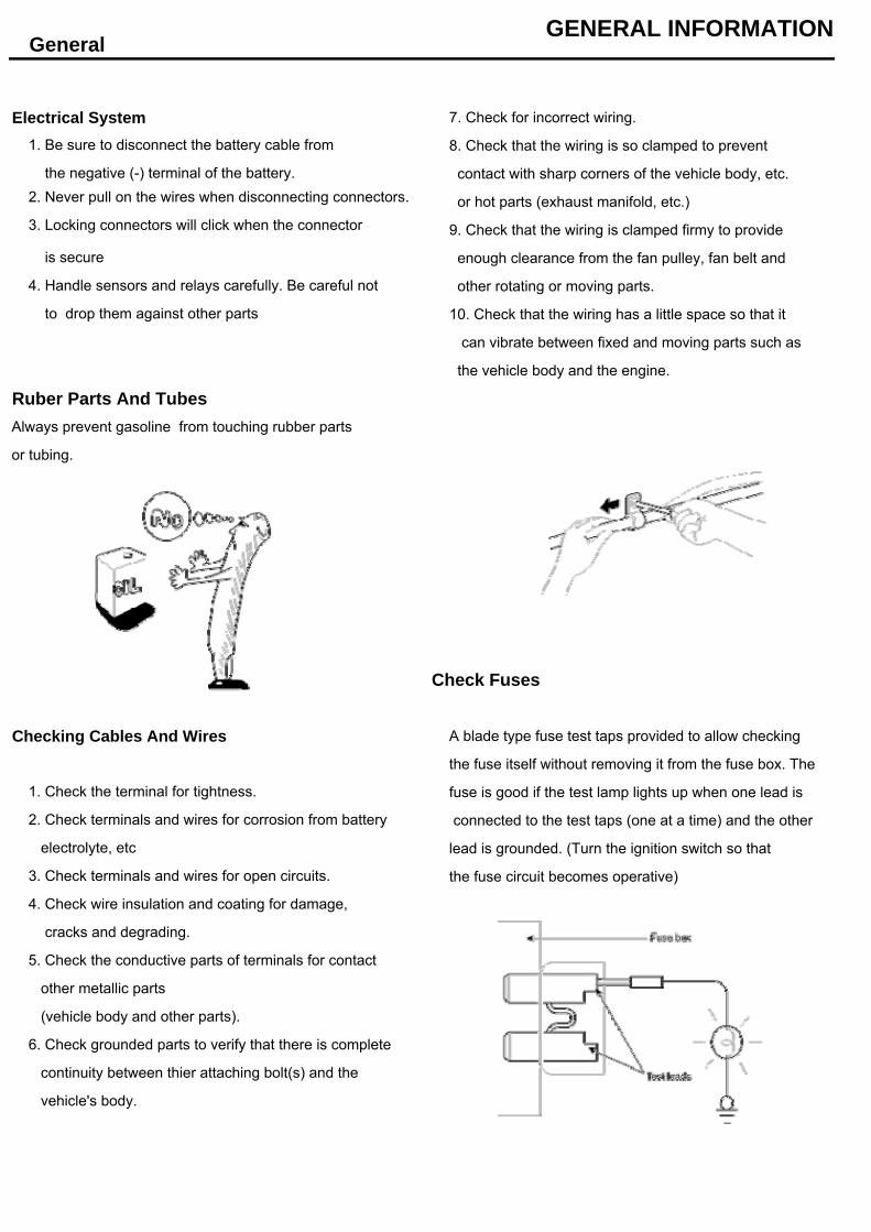
Ruber Parts And TubesAlways prevent gasoline from touching rubber parts
or tubing.
Check Fuses
Checking Cables And Wires A blade type fuse test taps provided to allow checking
the fuse itself without removing it from the fuse box. The
fuse is good if the test lamp lights up when one lead is
connected to the test taps (one at a time) and the other
lead is grounded. (Turn the ignition switch so that
the fuse circuit becomes operative)
GENERAL INFORMATION
5. Check the conductive parts of terminals for contact
(vehicle body and other parts).
2. Never pull on the wires when disconnecting connectors.
4. Check wire insulation and coating for damage,
4. Handle sensors and relays carefully. Be careful not
1. Be sure to disconnect the battery cable from
General
3. Locking connectors will click when the connector
is secure
the negative (-) terminal of the battery.
6. Check grounded parts to verify that there is complete
continuity between thier attaching bolt(s) and the
vehicle's body.
to drop them against other parts
other metallic parts
1. Check the terminal for tightness.
2. Check terminals and wires for corrosion from battery
electrolyte, etc
3. Check terminals and wires for open circuits.
cracks and degrading.
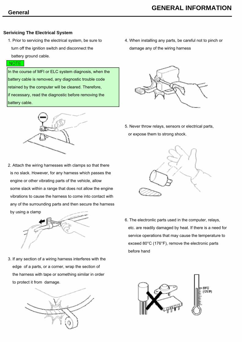
Serivicing The Electrical System1. Prior to servicing the electrical system, be sure to 4. When installing any parts, be careful not to pinch or
turn off the ignition switch and disconnect the damage any of the wiring harness
battery ground cable.
In the course of MFI or ELC system diagnosis, when the
5. Never throw relays, sensors or electrical parts,
or expose them to strong shock.
2. Attach the wiring harnesses with clamps so that there
6. The electronlic parts used in the computer, relays,
etc. are readily damaged by heat. If there is a need for
service operations that may cause the temperature to
exceed 80°C (176°F), remove the electronic parts
before hand
3. If any section of a wiring harness interferes with the
battery cable is removed, any diagnostic trouble code
vibrations to cause the harness to come into contact with
any of the surrounding parts and then secure the harness
by using a clamp
some slack within a range that does not allow the engine
GeneralGENERAL INFORMATION
retained by the computer will be cleared. Therefore,
if necessary, read the diagnostic before removing the
is no slack. However, for any harness which passes the
engine or other vibrating parts of the vehicle, allow
edge of a parts, or a corner, wrap the section of
battery cable.
the harness with tape or something similar in order
to protect it from damage.
NOTE
7. Loose connectors cause problems. Make sure that
the connectors are always securely fastened.
10. Connect connectors which have catches by inserting
the connectors until they make a clicking sound
8. When disconnecting a connector, be sure to grip
only the connector, not the wires.
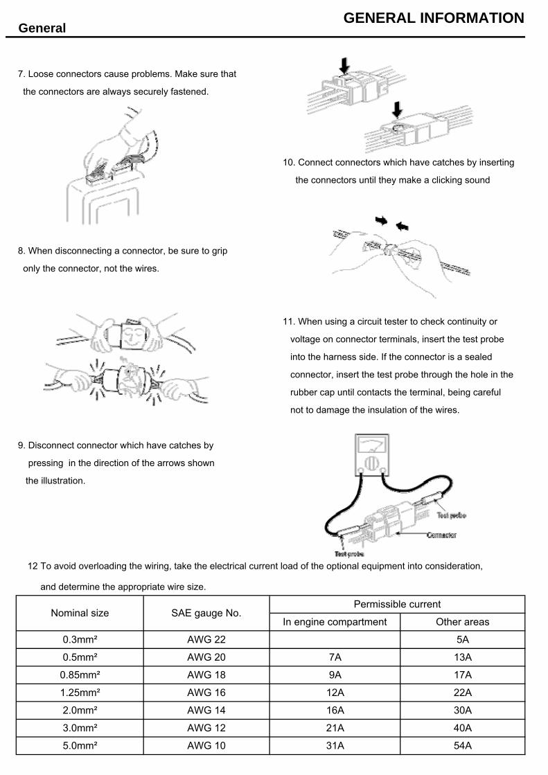
11. When using a circuit tester to check continuity or
voltage on connector terminals, insert the test probe
into the harness side. If the connector is a sealed
connector, insert the test probe through the hole in the
rubber cap until contacts the terminal, being careful
not to damage the insulation of the wires.
9. Disconnect connector which have catches by
pressing in the direction of the arrows shown
the illustration.
12
and determine the appropriate wire size.
GeneralGENERAL INFORMATION
0.85mm² AWG 18
3.0mm²
AWG 22
In engine compartment
0.3mm²
Other areas
To avoid overloading the wiring, take the electrical current load of the optional equipment into consideration,
0.5mm² AWG 20 7A 13A
5A
Permissible currentNominal size SAE gauge No.
17A
1.25mm² AWG 16 12A 22A
5.0mm² AWG 10 31A
9A
16A 30A
AWG 12 21A 40A
54A
2.0mm² AWG 14
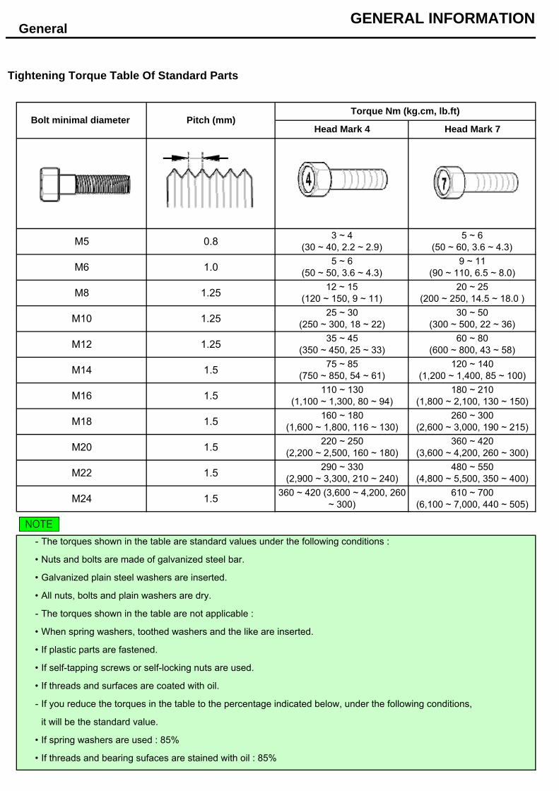
Tightening Torque Table Of Standard Parts
-
•
•
•
-
•
•
•
•
-
•
•
If plastic parts are fastened.
it will be the standard value.
GeneralGENERAL INFORMATION
3 ~ 4(30 ~ 40, 2.2 ~ 2.9)
5 ~ 6(50 ~ 50, 3.6 ~ 4.3)
12 ~ 15(120 ~ 150, 9 ~ 11)
25 ~ 30(250 ~ 300, 18 ~ 22)
35 ~ 45(350 ~ 450, 25 ~ 33)
75 ~ 85(750 ~ 850, 54 ~ 61)
110 ~ 130(1,100 ~ 1,300, 80 ~ 94)
160 ~ 180(1,600 ~ 1,800, 116 ~ 130)
1.5
M24 1.5
220 ~ 250(2,200 ~ 2,500, 160 ~ 180)
290 ~ 330(2,900 ~ 3,300, 210 ~ 240)
360 ~ 420 (3,600 ~ 4,200, 260~ 300)
1.5
5 ~ 6(50 ~ 60, 3.6 ~ 4.3)
9 ~ 11(90 ~ 110, 6.5 ~ 8.0)
20 ~ 25(200 ~ 250, 14.5 ~ 18.0 )
30 ~ 50(300 ~ 500, 22 ~ 36)
60 ~ 80(600 ~ 800, 43 ~ 58)
120 ~ 140(1,200 ~ 1,400, 85 ~ 100)
180 ~ 210(1,800 ~ 2,100, 130 ~ 150)
260 ~ 300(2,600 ~ 3,000, 190 ~ 215)
Nuts and bolts are made of galvanized steel bar.
360 ~ 420(3,600 ~ 4,200, 260 ~ 300)
480 ~ 550(4,800 ~ 5,500, 350 ~ 400)
610 ~ 700(6,100 ~ 7,000, 440 ~ 505)
M22 1.5
M20
The torques shown in the table are not applicable :
M14 1.5
When spring washers, toothed washers and the like are inserted.
Galvanized plain steel washers are inserted.
M16 1.5
All nuts, bolts and plain washers are dry.
The torques shown in the table are standard values under the following conditions :
M18
M6 1.0
If spring washers are used : 85%
M8 1.25
If threads and surfaces are coated with oil.
M10 1.25
1.25
If self-tapping screws or self-locking nuts are used.
If you reduce the torques in the table to the percentage indicated below, under the following conditions,
If threads and bearing sufaces are stained with oil : 85%
M12
Torque Nm (kg.cm, lb.ft)
Head Mark 4 Head Mark 7
M5 0.8
Bolt minimal diameter Pitch (mm)
NOTE
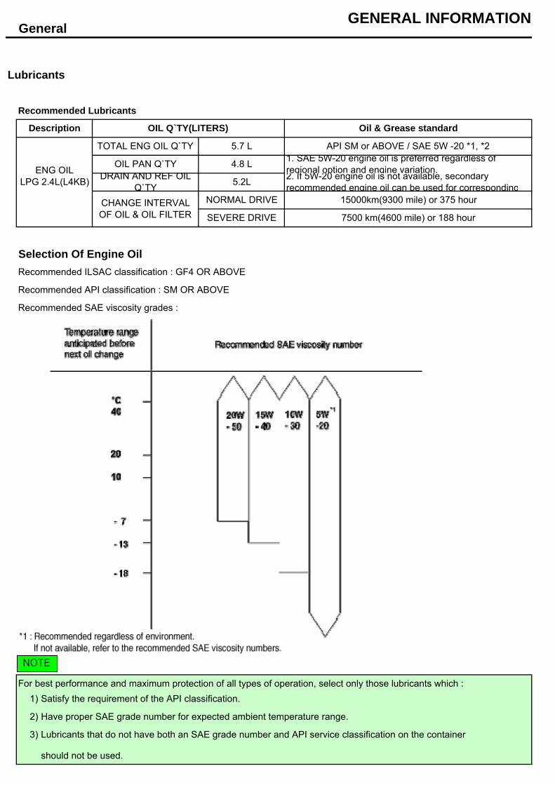
Lubricants
Recommended Lubricants
Selection Of Engine OilRecommended ILSAC classification : GF4 OR ABOVE
Recommended API classification : SM OR ABOVE
Recommended SAE viscosity grades :
1)
2)
3)
should not be used.
GeneralGENERAL INFORMATION
2. If 5W-20 engine oil is not available, secondaryrecommended engine oil can be used for corresponding
CHANGE INTERVALOF OIL & OIL FILTER
NORMAL DRIVE 15000km(9300 mile) or 375 hour
SEVERE DRIVE 7500 km(4600 mile) or 188 hour
ENG OILLPG 2.4L(L4KB) DRAIN AND REF OIL
Q`TY
API SM or ABOVE / SAE 5W -20 *1, *2
OIL PAN Q`TY 4.8 L 1. SAE 5W-20 engine oil is preferred regardless ofregional option and engine variation.
TOTAL ENG OIL Q`TY 5.7 L
5.2L
Description OIL Q`TY(LITERS) Oil & Grease standard
Lubricants that do not have both an SAE grade number and API service classification on the container
For best performance and maximum protection of all types of operation, select only those lubricants which :Satisfy the requirement of the API classification.
Have proper SAE grade number for expected ambient temperature range.
NOTE
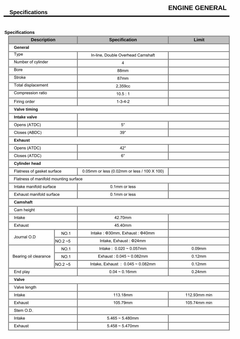
Specifications
Specifications
NO.1
NO.2 ~5
NO.1
NO.1
NO.2 ~5
Exhaust 5.458 ~ 5.470mm
Stem O.D.
Intake 5.465 ~ 5.480mm
Intake 113.18mm 112.93mm min
Exhaust 105.79mm 105.74mm min
Valve
Valve length
Intake, Exhaust : 0.045 ~ 0.082mm 0.12mm
End play 0.04 ~ 0.16mm 0.24mm
Bearing oil clearance
Intake : 0.020 ~ 0.057mm 0.09mm
Exhaust : 0.045 ~ 0.082mm 0.12mm
Exhaust 45.40mm
Intake : Φ30mm, Exhaust : Φ40mmJournal O.D
Intake, Exhaust : Φ24mm
Cam height
Intake 42.70mm
Exhaust manifold surface 0.1mm or less
Camshaft
Intake manifold surface 0.1mm or less
Flatness of manifold mounting surface
Cylinder head
Flatness of gasket surface 0.05mm or less (0.02mm or less / 100 X 100)
Opens (ATDC) 42°
Closes (ATDC) 6°
Closes (ABDC) 39°
Exhaust
Intake valve
Opens (ATDC) 5°
Valve timing
Firing order 1-3-4-2
Compression ratio 10.5 : 1
Total displacement 2,359cc
Stroke 87mm
Bore 88mm
Number of cylinder 4
Type In-line, Double Overhead Camshaft
Limit
ENGINE GENERAL
General
Description Specification
Specifications
Valve stem to valve guide clearance
ENGINE GENERAL
Exhaust
Tappet bore inner dia
MLA out dia
Intake
Intake
Width of seat contact
Valve seat
MLA & Tappet bore claearance
Squareness
Load
Free length
Exhaust
Exhaust
Intake
Cold (20°C[68°F])
Valve clearance
Piston
Out-of-round and taper of cylinder bore
Cylinder bore
Cylinder block
No.1
Ring groove width
Clearance with cylinder bore
O.D (To set limits to new parts)
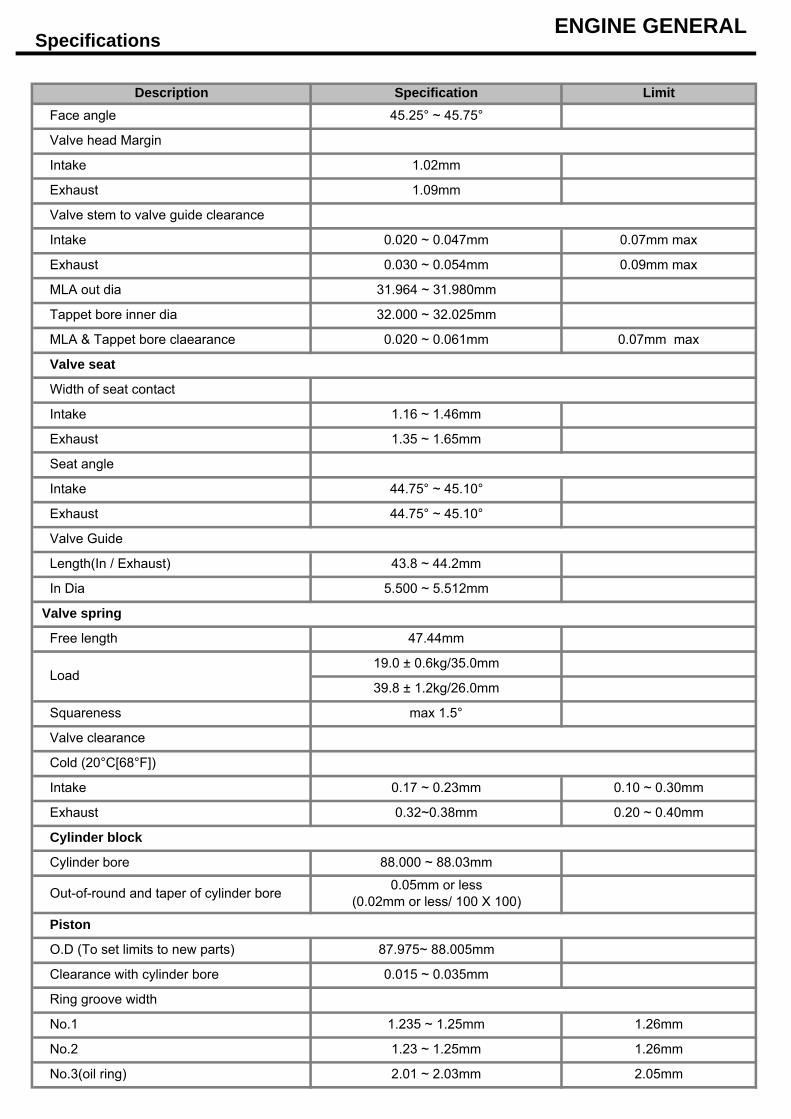
88.000 ~ 88.03mm
0.05mm or less(0.02mm or less/ 100 X 100)
87.975~ 88.005mm
No.3(oil ring) 2.01 ~ 2.03mm
0.015 ~ 0.035mm
1.235 ~ 1.25mm
1.23 ~ 1.25mmNo.2
0.17 ~ 0.23mm
0.32~0.38mm
19.0 ± 0.6kg/35.0mm
39.8 ± 1.2kg/26.0mm
max 1.5°
47.44mm
Valve Guide
Intake
Seat angle
1.35 ~ 1.65mm
44.75° ~ 45.10°
44.75° ~ 45.10°
2.05mm
1.26mm
1.26mm
0.20 ~ 0.40mm
0.10 ~ 0.30mm
Valve spring
43.8 ~ 44.2mm
5.500 ~ 5.512mmIn Dia
Length(In / Exhaust)
Valve head Margin
1.16 ~ 1.46mm
0.07mm max
0.07mm max
0.09mm max
0.020 ~ 0.047mm
Description Specification LimitFace angle 45.25° ~ 45.75°
1.09mm
1.02mm
Exhaust
Intake
31.964 ~ 31.980mm
32.000 ~ 32.025mm
0.020 ~ 0.061mm
0.030 ~ 0.054mmExhaust
Specifications
82 ± 1.5°C
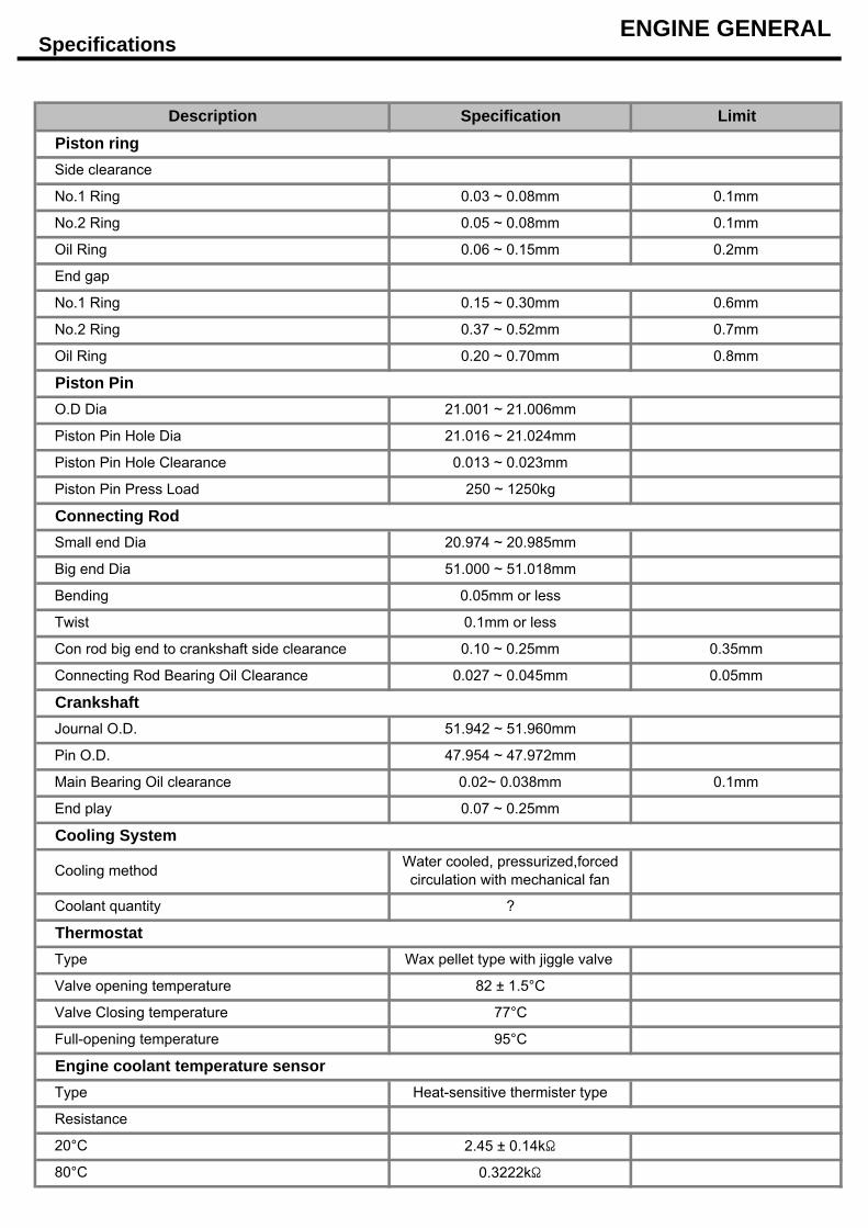
Piston ring
0.03 ~ 0.08mm
Side clearance
No.1 Ring 0.1mm
Cooling method Water cooled, pressurized,forcedcirculation with mechanical fan
2.45 ± 0.14kΩ
Full-opening temperature 95°C
80°C 0.3222kΩ
Type Heat-sensitive thermister type
Resistance
20°C
Valve Closing temperature 77°C
ThermostatType Wax pellet type with jiggle valve
Valve opening temperature
Coolant quantity ?
End play 0.07 ~ 0.25mm
Cooling System
Pin O.D. 47.954 ~ 47.972mm
Main Bearing Oil clearance 0.02~ 0.038mm 0.1mm
Connecting Rod Bearing Oil Clearance 0.027 ~ 0.045mm 0.05mm
Engine coolant temperature sensor
CrankshaftJournal O.D. 51.942 ~ 51.960mm
Small end Dia 20.974 ~ 20.985mm
Big end Dia 51.000 ~ 51.018mm
Piston Pin Press Load 250 ~ 1250kg
Connecting Rod
Piston Pin Hole Dia 21.016 ~ 21.024mm
Piston Pin Hole Clearance 0.013 ~ 0.023mm
O.D Dia 21.001 ~ 21.006mm
Piston PinOil Ring 0.20 ~ 0.70mm 0.8mm
No.2 Ring 0.37 ~ 0.52mm 0.7mm
0.1mm
0.2mm
No.1 Ring 0.15 ~ 0.30mm 0.6mm
End gap
Oil Ring
0.05 ~ 0.08mm
0.06 ~ 0.15mm
No.2 Ring
Description Specification Limit
ENGINE GENERAL
Con rod big end to crankshaft side clearance 0.10 ~ 0.25mm 0.35mm
Bending 0.05mm or less
Twist 0.1mm or less
Specifications
Q`TY N.m kgf.m lb-ft9 23.5 ~ 27.4 2.4 ~ 2.8 17.4 ~ 20.2
4 23.5 ~ 27.4 2.4 ~ 2.8 17.4 ~ 20.2
9 18.6 ~ 22.5 1.9 ~ 2.3 13.7 ~ 16.6
9 7.8 ~ 9.8 0.8 ~ 1.0 5.8 ~ 7.2
16 9.8 ~ 11.8 1.0 ~ 1.2 7.2 ~ 8.7
16 10.8 ~ 12.7 1.1 ~ 1.3 7.9 ~ 9.4
4 27.4 ~ 31.4 2.8 ~ 3.2 20.3 ~ 23.1
10 34.3 + 90° + 90° 3.5 + 90° +90° 25.3 + 90° + 90°
18 7.8 ~ 9.8 0.8 ~ 1.0 5.8 ~ 7.2
1 166.6 ~ 176.4 17.0 ~ 18.0 122.9 ~ 130.1
7 117.6 ~ 127.4 12.0 ~ 13.0 86.8 ~ 93.9
7 117.6 ~ 127.4 12.0 ~ 13.0 86.8 ~ 93.9
2 9.8 ~ 11.8 1.0 ~ 1.2 7.2 ~ 8.7
1 9.8 ~ 11.8 1.0 ~ 1.2 7.2 ~ 8.7
3 9.8 ~ 11.8 1.0 ~ 1.2 7.2 ~ 8.7
2 53.9 ~ 63.7 5.5 ~ 6.5 39.7 ~ 47.0
2 9.8 ~ 11.8 1.0 ~ 1.2 7.2 ~ 8.7
1 9.8 ~ 11.8 1.0 ~ 1.2 7.2 ~ 8.7
3 18.6 ~ 23.5 1.9 ~ 2.4 13.7 ~ 17.4
2 18.6 ~ 23.5 1.9 ~ 2.4 13.7 ~ 17.4
2 39.2 ~ 44.1 4.0 ~ 4.5 28.9 ~ 32.5
3 39.2 ~ 44.1 4.0 ~ 4.5 28.9 ~ 32.5
2 18.6 ~ 23.5 1.9 ~ 2.4 13.7 ~ 17.4
2 18.6 ~ 23.5 1.9 ~ 2.4 13.7 ~ 17.4
1 7.8 ~ 11.8 0.8 ~ 1.2 5.8 ~ 8.7
4 9.8 ~ 11.8 1.0 ~ 1.2 7.2 ~ 8.7
3 18.6 ~ 27.5 1.9 ~ 2.8 13.7 ~ 20.3
2 18.6 ~ 27.5 1.9 ~ 2.8 13.7 ~ 20.3
8 18.6 ~ 27.5 1.9 ~ 2.8 13.7 ~ 20.3
3 7.8 ~ 11.8 0.8 ~ 1.2 5.8 ~ 8.7
7 49.0 ~ 53.9 5.0 ~ 5.5 36.2 ~ 39.8
1 9.8 ~ 11.8 1.0 ~ 1.2 7.2 ~ 8.7
1 39.2 ~ 49.0 4.0 ~ 5.0 28.9 ~ 36.1
1 18.6 ~ 23.5 1.9 ~ 2.4 13.7 ~ 17.4
1 19.6~ 44.1 2.0 ~ 4.0 14.5
1 9.8 ~ 11.8 1.0 ~ 1.2 7.2 ~ 8.7
1 7.8 ~ 11.8 0.8 ~ 1.2 5.8 ~ 8.7
10 29.4 + 120° 3.0 + 120° 21.7 +120°
1 11.8 ~ 15.7 1.2 ~ 1.6 8.7 ~ 11.6
8 19.6 + 90° 2.0 + 90° 14.5 + 90°
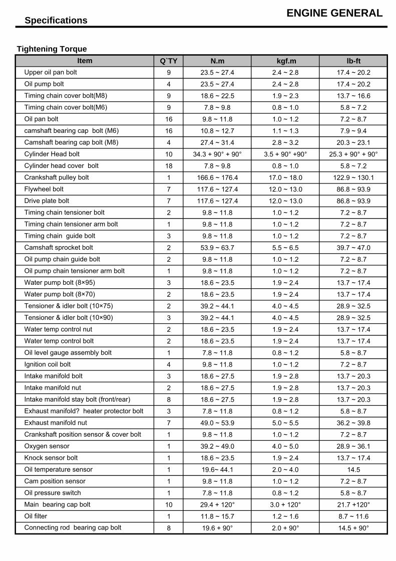
Oil filter
Oil pressure switch
Main bearing cap bolt
Tensioner & idler bolt (10×75)
Tensioner & idler bolt (10×90)
Oil temperature sensor
Cam position sensor
Oxygen sensor
Knock sensor bolt
Exhaust manifold nut
Water temp control nut
Connecting rod bearing cap bolt
Water temp control bolt
Oil level gauge assembly bolt
Ignition coil bolt
Crankshaft position sensor & cover bolt
Intake manifold stay bolt (front/rear)
Exhaust manifold? heater protector bolt
Intake manifold bolt
Intake manifold nut
Water pump bolt (8×70)
Oil pump chain tensioner arm bolt
Water pump bolt (8×95)
Camshaft sprocket bolt
Oil pump chain guide bolt
Timing chain tensioner arm bolt
Timing chain guide bolt
Drive plate bolt
Timing chain tensioner bolt
Crankshaft pulley bolt
Flywheel bolt
Cylinder Head bolt
Cylinder head cover bolt
camshaft bearing cap bolt (M6)
Camshaft bearing cap bolt (M8)
Timing chain cover bolt(M6)
Oil pan bolt
Tightening Torque
ENGINE GENERAL
Oil pump bolt
Timing chain cover bolt(M8)
ItemUpper oil pan bolt
Compression
InspectionCompression Pressure Inspection
speed of 250 rpm or more
as possible.
Compression pressure :
Difference between each cylinder :
100kPa (1.0kgf/cm², 15psi) or less
5) If the cylinder compression in 1 or more cylinders is low,
pour a small amount of engine oil into the cylinder through
the spark plug hole and repeat steps (1) through (3) for
cylinders with low compression.
piston rings and/or cylinder bore are worn or damaged.
4.Check cylinder compression pressure.
7. Connect the injector connectors and ignition coil connectors.
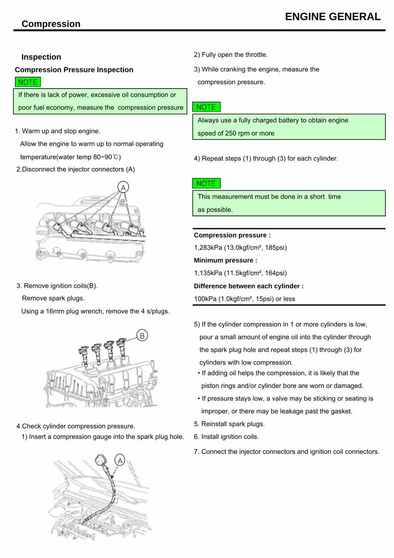
1) Insert a compression gauge into the spark plug hole.
• If pressure stays low, a valve may be sticking or seating is
5. Reinstall spark plugs.
6. Install ignition coils.
• If adding oil helps the compression, it is likely that the
improper, or there may be leakage past the gasket.
ENGINE GENERAL
2) Fully open the throttle.
1,135kPa (11.5kgf/cm², 164psi)
4) Repeat steps (1) through (3) for each cylinder.
This measurement must be done in a short time
Minimum pressure :
1,283kPa (13.0kgf/cm², 185psi)
3) While cranking the engine, measure the
compression pressure.
Always use a fully charged battery to obtain engine
If there is lack of power, excessive oil consumption or
poor fuel economy, measure the compression pressure
1. Warm up and stop engine.
Allow the engine to warm up to normal operating
2.Disconnect the injector connectors (A)
temperature(water temp 80~90)
3. Remove ignition coils(B).
Remove spark plugs.
Using a 16mm plug wrench, remove the 4 s/plugs.
B
A
A
NOTE
NOTE
NOTE
Valve Clearance
Inspect and adjust the valve clearance when the
engine is cold
(Engine coolant temperature : 20°C (68°F)) and
cylinder head is installed on the cylinder block.
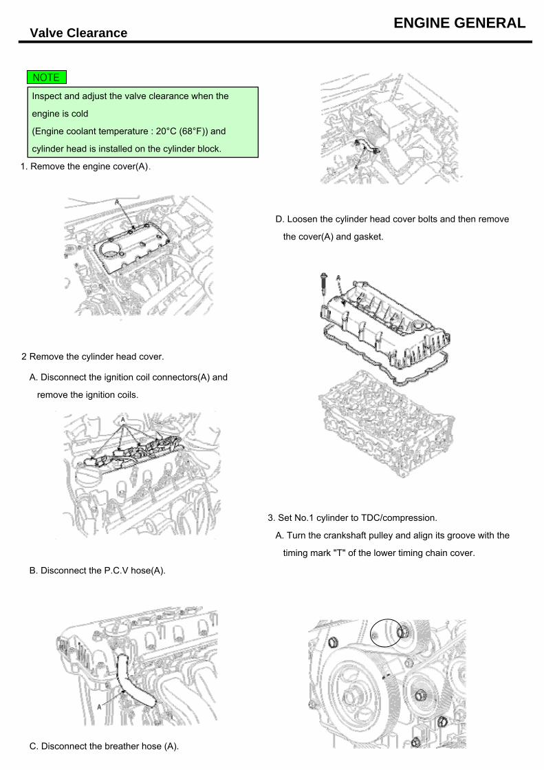
1. Remove the engine cover(A).
D. Loosen the cylinder head cover bolts and then remove
the cover(A) and gasket.
2
A. Disconnect the ignition coil connectors(A) and
remove the ignition coils.
3. Set No.1 cylinder to TDC/compression.
A. Turn the crankshaft pulley and align its groove with the
timing mark "T" of the lower timing chain cover.
B. Disconnect the P.C.V hose(A).
C. Disconnect the breather hose (A).
Remove the cylinder head cover.
ENGINE GENERAL
NOTE
Adjustment
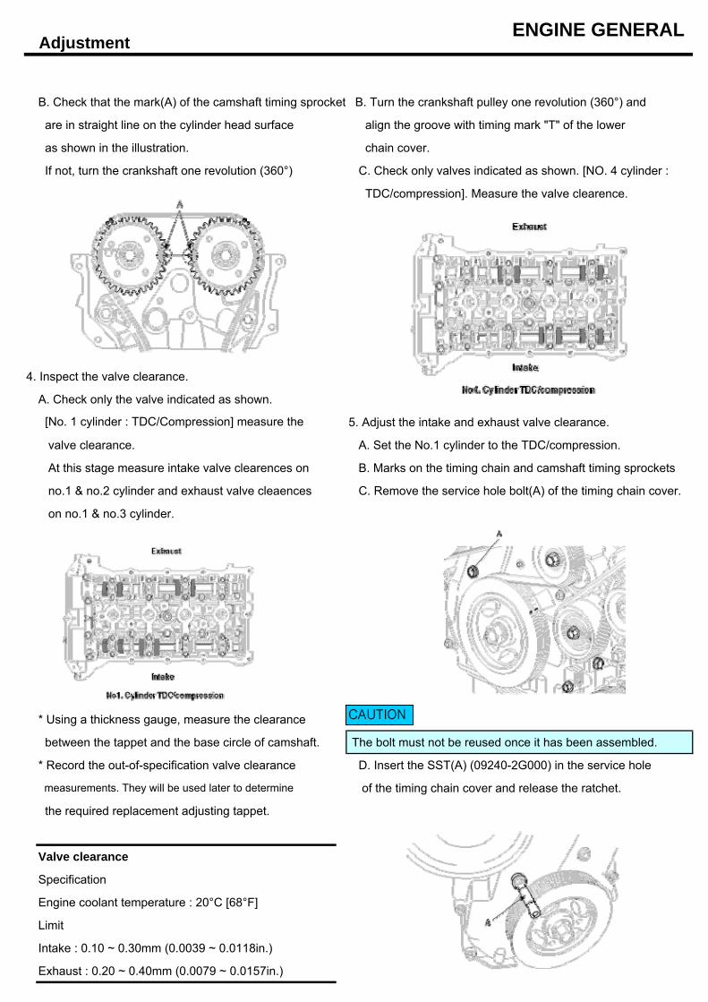
B. Check that the mark(A) of the camshaft timing sprocket B. Turn the crankshaft pulley one revolution (360°) and
are in straight line on the cylinder head surface align the groove with timing mark "T" of the lower
as shown in the illustration. chain cover.
If not, turn the crankshaft one revolution (360°) C. Check only valves indicated as shown. [NO. 4 cylinder :
TDC/compression]. Measure the valve clearence.
4. Inspect the valve clearance.
A. Check only the valve indicated as shown.
5. Adjust the intake and exhaust valve clearance.
valve clearance. A. Set the No.1 cylinder to the TDC/compression.
At this stage measure intake valve clearences on B. Marks on the timing chain and camshaft timing sprockets
no.1 & no.2 cylinder and exhaust valve cleaences C. Remove the service hole bolt(A) of the timing chain cover.
on no.1 & no.3 cylinder.
* Using a thickness gauge, measure the clearance
between the tappet and the base circle of camshaft. The bolt must not be reused once it has been assembled.
* Record the out-of-specification valve clearance D. Insert the SST(A) (09240-2G000) in the service hole
measurements. They will be used later to determine of the timing chain cover and release the ratchet.
the required replacement adjusting tappet.
Valve clearance
Specification
Engine coolant temperature : 20°C [68°F]
Limit
Intake : 0.10 ~ 0.30mm (0.0039 ~ 0.0118in.)
Exhaust : 0.20 ~ 0.40mm (0.0079 ~ 0.0157in.)
[No. 1 cylinder : TDC/Compression] measure the
ENGINE GENERAL
CAUTION
Adjustment
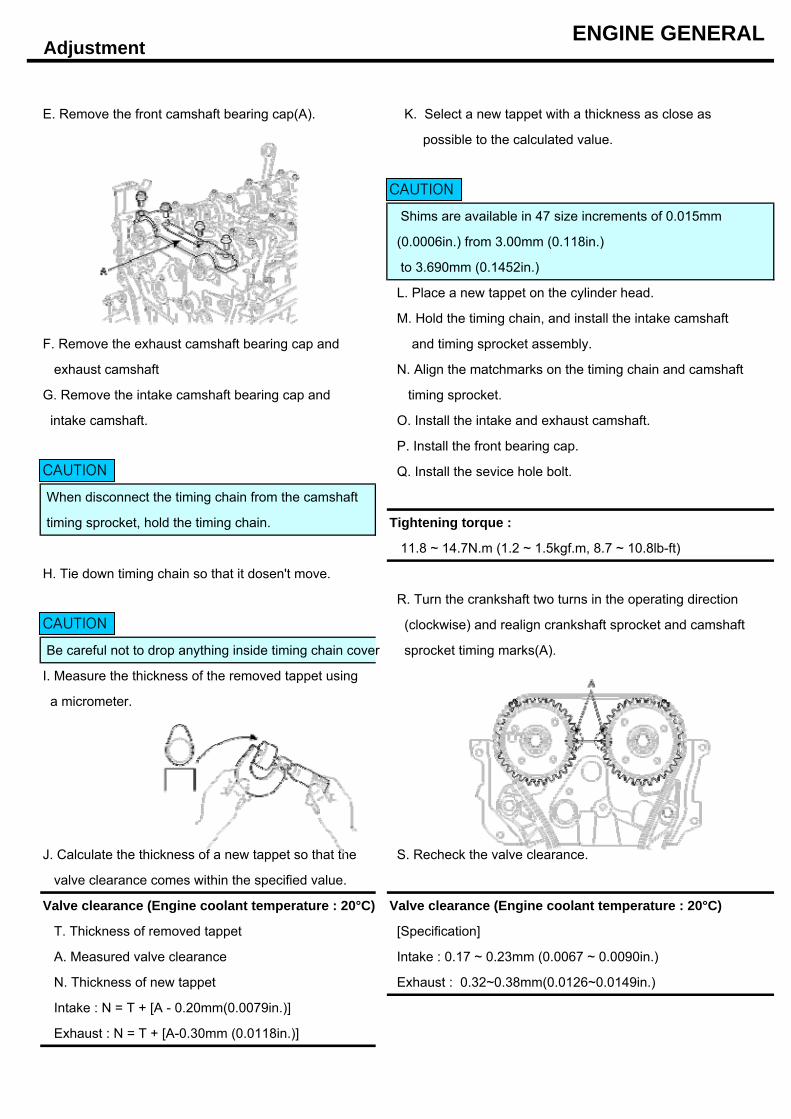
E. Remove the front camshaft bearing cap(A). K. Select a new tappet with a thickness as close as
possible to the calculated value.
Shims are available in 47 size increments of 0.015mm
(0.0006in.) from 3.00mm (0.118in.)
to 3.690mm (0.1452in.)
L. Place a new tappet on the cylinder head.
M. Hold the timing chain, and install the intake camshaft
F. Remove the exhaust camshaft bearing cap and and timing sprocket assembly.
exhaust camshaft N. Align the matchmarks on the timing chain and camshaft
G. Remove the intake camshaft bearing cap and timing sprocket.
intake camshaft. O. Install the intake and exhaust camshaft.
P. Install the front bearing cap.
Q. Install the sevice hole bolt.
When disconnect the timing chain from the camshaft
timing sprocket, hold the timing chain. Tightening torque :
11.8 ~ 14.7N.m (1.2 ~ 1.5kgf.m, 8.7 ~ 10.8lb-ft)
H. Tie down timing chain so that it dosen't move.
R. Turn the crankshaft two turns in the operating direction
(clockwise) and realign crankshaft sprocket and camshaft
Be careful not to drop anything inside timing chain cover sprocket timing marks(A).
I. Measure the thickness of the removed tappet using
a micrometer.
J. Calculate the thickness of a new tappet so that the S. Recheck the valve clearance.
valve clearance comes within the specified value.
Valve clearance (Engine coolant temperature : 20°C) Valve clearance (Engine coolant temperature : 20°C)
T. Thickness of removed tappet [Specification]
A. Measured valve clearance Intake : 0.17 ~ 0.23mm (0.0067 ~ 0.0090in.)
N. Thickness of new tappet Exhaust : 0.32~0.38mm(0.0126~0.0149in.)
Intake : N = T + [A - 0.20mm(0.0079in.)]
Exhaust : N = T + [A-0.30mm (0.0118in.)]
ENGINE GENERAL
CAUTION
CAUTION
CAUTION
TroubleshootingENGINE GENERAL
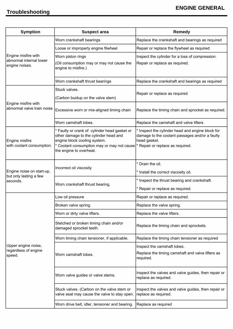
Symption Suspect area Remedy
Worn crankshaft bearings Replace the crankshaft and bearings as required
Loose or improperly engine filwheel Repair or replace the flywheel as required
Worn piston rings Inspect the cylinder for a loss of compression.
Repair or replace as required.
Worn crankshaft thrust bearings Replace the crankshaft and bearings as required
Stuck valves.
(Carbon buidup on the valve stem)
Worn camshaft lobes. Replace the camshaft and valve lifters.
* Drain the oil.
* Install the correct viscosity oil.
* Inspect the thrust bearing and crankshaft.
* Repair or replace as required.
Low oil pressure Repair or replace as required.
Broken valve spring. Replace the valve spring.
Worn or dirty valve lifters. Replace the valve lifters.
Worn timing chain tensioner, if applicable. Replace the timing chain tensioner as required
Inspect the camshaft lobes.
Worn drive belt, idler, tensioner and bearing. Replace as required
Upper engine noise,regardless of enginespeed.
Inspect the valves and valve guides, then repair orreplace as required.
Replace the timing chain and sprockets.
Replace the timing camshaft and valve lifters asrequired.
Stetched or broken timing chain and/ordamaged sprocket teeth.
Worn camshaft lobes.
Worn valve guides or valve stems.
Inspect the valves and valve guides, then repair orreplace as required.
Stuck valves. (Carbon on the valve stem orvalve seat may cause the valve to stay open.
* Repair or replace as required.
Engine noise on start-up,but only lasting a fewseconds.
Incorrect oil viscosity
Worn crankshaft thrust bearing.
(Oil consumption may or may not cause theengine to misfire.)
Engine misfire withabnormal internal lowerengine noises.
* Faulty or crank of cylinder head gasket orother damage to the cylinder head andengine block cooling system.
* Inspect the cylinder head and engine block fordamage to the coolant passages and/or a faultyhead gasket.Engine misfire
with coolant consumption.
Engine misfire withabnormal valve train noise.
Repair or replace as required
* Coolant consumption may or may not causethe engine to overheat.
Excessive worn or mis-aligned timing chain Replace the timing chain and sprocket as required.
TroubleshootingENGINE GENERAL
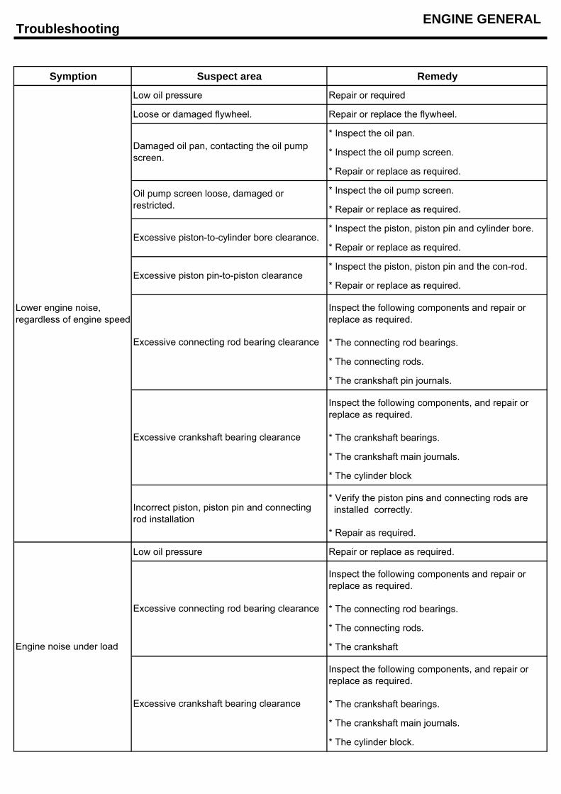
Symption Suspect area Remedy
Low oil pressure Repair or required
Loose or damaged flywheel. Repair or replace the flywheel.
* Inspect the oil pan.
* Inspect the oil pump screen.
* Repair or replace as required.
* Inspect the oil pump screen.
* Repair or replace as required.
* Inspect the piston, piston pin and cylinder bore.
* Repair or replace as required.
* Inspect the piston, piston pin and the con-rod.
* Repair or replace as required.
* The connecting rod bearings.
* The connecting rods.
* The crankshaft pin journals.
* The crankshaft bearings.
* The crankshaft main journals.
* The cylinder block
* Repair as required.
Low oil pressure Repair or replace as required.
* The connecting rod bearings.
* The connecting rods.
* The crankshaft
* The crankshaft bearings.
* The crankshaft main journals.
* The cylinder block.
Inspect the following components, and repair orreplace as required.
Excessive connecting rod bearing clearance
Inspect the following components and repair orreplace as required.
Inspect the following components, and repair orreplace as required.
* Verify the piston pins and connecting rods are installed correctly.
Engine noise under load
Oil pump screen loose, damaged orrestricted.
Excessive piston-to-cylinder bore clearance.
Excessive piston pin-to-piston clearance
Excessive crankshaft bearing clearance
Excessive crankshaft bearing clearance
Excessive connecting rod bearing clearance
Incorrect piston, piston pin and connectingrod installation
Inspect the following components and repair orreplace as required.
Lower engine noise,regardless of engine speed
Damaged oil pan, contacting the oil pumpscreen.
TroubleshootingENGINE GENERAL
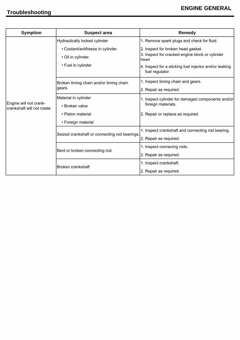
Symption Suspect area Remedy
Hydraulically locked cylinder 1. Remove spark plugs and check for fluid.
• Coolant/antifreeze in cylinder. 2. Inspect for broken head gasket.
• Oil in cylinder. 3. Inspect for cracked engine block or cylinderhead.
• Fuel in cylinder
1. Inspect timing chain and gears.
2. Repair as required.
Material in cylinder
• Broken valve
• Piston material 2. Repair or replace as required.
• Foreign material
1. Inspect crankshaft and connecting rod bearing.
2. Repair as required.
1. Inspect connecing rods.
2. Repair as required.
1. Inspect crankshaft.
2. Repair as required.
Engine will not crank-crankshaft will not rotate
Broken crankshaft
Broken timing chain and/or timing chaingears.
1. Inspect cylinder for damaged components and/or foreign materials.
4. Inspect for a sticking fuel injector and/or leaking fuel regulator.
Seized crankshaft or connecting rod bearings.
Bent or broken connecting rod.
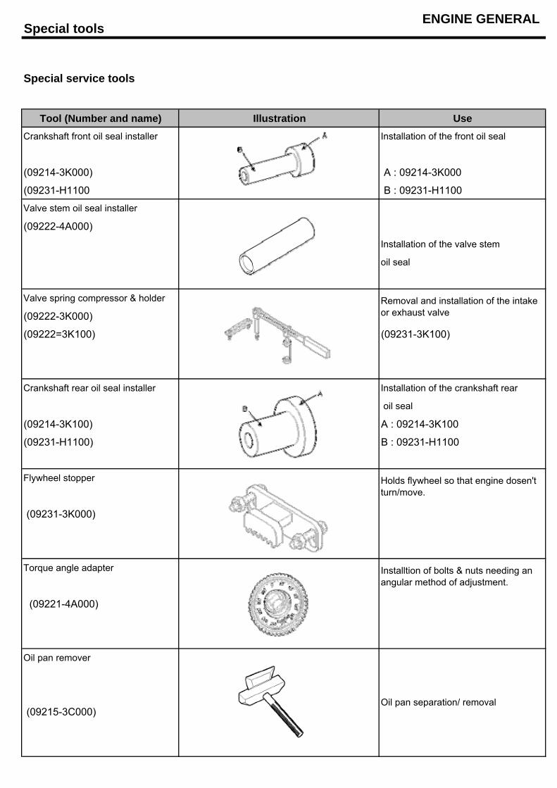
Special toolsENGINE GENERAL
Special service tools
Tool (Number and name) Illustration UseCrankshaft front oil seal installer Installation of the front oil seal
(09214-3K000) A : 09214-3K000
(09231-H1100 B : 09231-H1100
Valve stem oil seal installer
(09222-4A000)
Installation of the valve stem
oil seal
Valve spring compressor & holder
(09222-3K000)
(09222=3K100) (09231-3K100)
Crankshaft rear oil seal installer Installation of the crankshaft rear
oil seal
(09214-3K100) A : 09214-3K100
(09231-H1100) B : 09231-H1100
Flywheel stopper
(09231-3K000)
Torque angle adapter
(09221-4A000)
Oil pan remover
(09215-3C000)
Holds flywheel so that engine dosen'tturn/move.
Oil pan separation/ removal
Installtion of bolts & nuts needing anangular method of adjustment.
Removal and installation of the intakeor exhaust valve
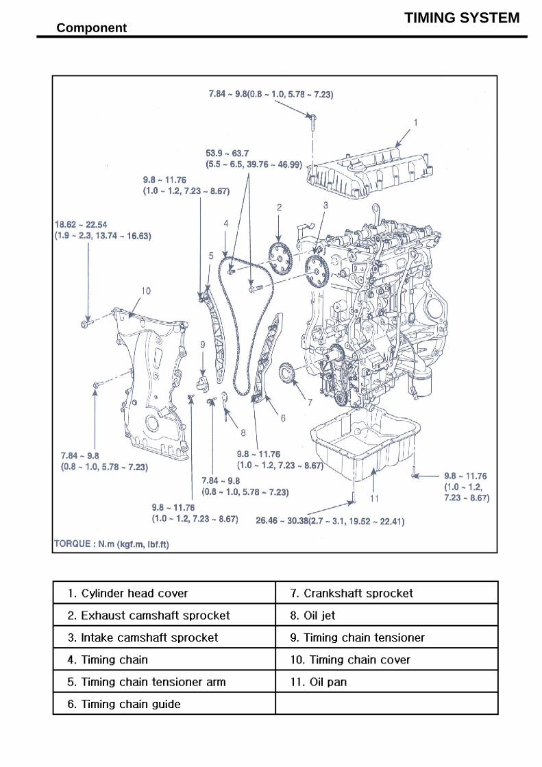
Component TIMING SYSTEM
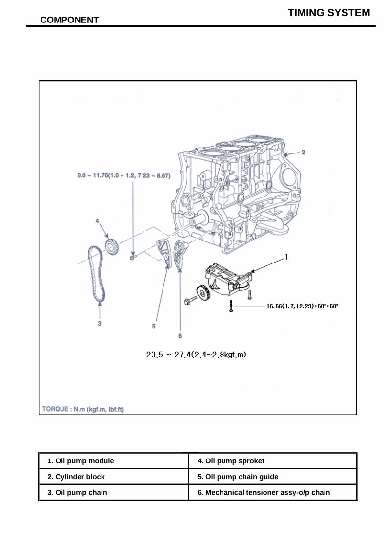
COMPONENT
1. Oil pump module 4. Oil pump sproket
2. Cylinder block 5. Oil pump chain guide
3. Oil pump chain 6. Mechanical tensioner assy-o/p chain
TIMING SYSTEM
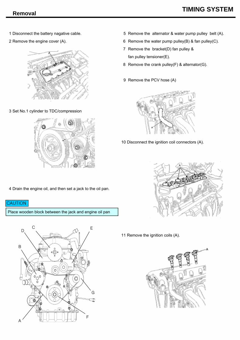
Removal TIMING SYSTEM
1 Disconnect the battery nagative cable. 5 Remove the alternator & water pump pulley belt (A).
2 Remove the engine cover (A). 6 Remove the water pump pulley(B) & fan pulley(C).
7 Remove the bracket(D) fan pulley &
fan pulley tensioner(E).
8 Remove the crank pulley(F) & alternator(G).
9 Remove the PCV hose (A)
3 Set No.1 cylinder to TDC/compression
10 Disconnect the ignition coil connectors (A).
4 Drain the engine oil, and then set a jack to the oil pan.
Place wooden block between the jack and engine oil pan
11 Remove the ignition coils (A).
CAUTION
A
B
CD
E
F
G
Removal TIMING SYSTEM
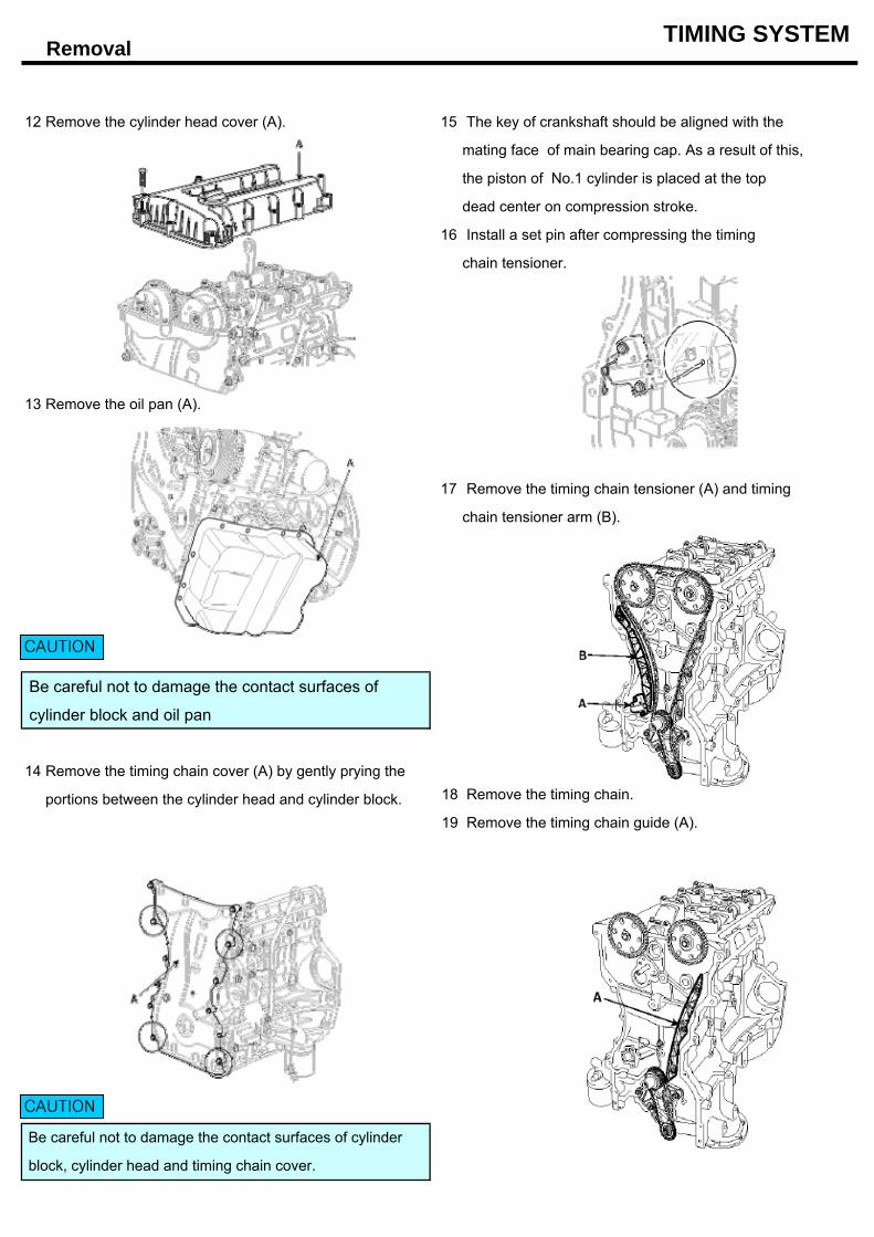
12 Remove the cylinder head cover (A). 15 The key of crankshaft should be aligned with the
mating face of main bearing cap. As a result of this,
the piston of No.1 cylinder is placed at the top
dead center on compression stroke.
16 Install a set pin after compressing the timing
chain tensioner.
13 Remove the oil pan (A).
17 Remove the timing chain tensioner (A) and timing
chain tensioner arm (B).
Be careful not to damage the contact surfaces of
cylinder block and oil pan
14 Remove the timing chain cover (A) by gently prying the
portions between the cylinder head and cylinder block. 18 Remove the timing chain.
19 Remove the timing chain guide (A).
Be careful not to damage the contact surfaces of cylinder
block, cylinder head and timing chain cover.
CAUTION
CAUTION
Removal / Inspection TIMING SYSTEM
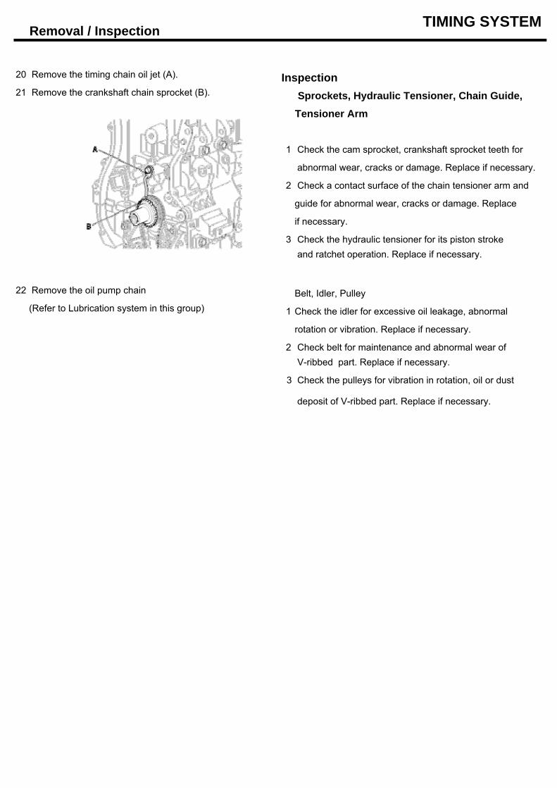
20 Remove the timing chain oil jet (A). Inspection21 Remove the crankshaft chain sprocket (B). Sprockets, Hydraulic Tensioner, Chain Guide,
Tensioner Arm
1 Check the cam sprocket, crankshaft sprocket teeth for
abnormal wear, cracks or damage. Replace if necessary.
2 Check a contact surface of the chain tensioner arm and
guide for abnormal wear, cracks or damage. Replace
if necessary.
3 Check the hydraulic tensioner for its piston stroke and ratchet operation. Replace if necessary.
22 Remove the oil pump chain Belt, Idler, Pulley(Refer to Lubrication system in this group) 1 Check the idler for excessive oil leakage, abnormal
rotation or vibration. Replace if necessary.
2 Check belt for maintenance and abnormal wear of V-ribbed part. Replace if necessary.
3 Check the pulleys for vibration in rotation, oil or dust
deposit of V-ribbed part. Replace if necessary.
Installation TIMING SYSTEM
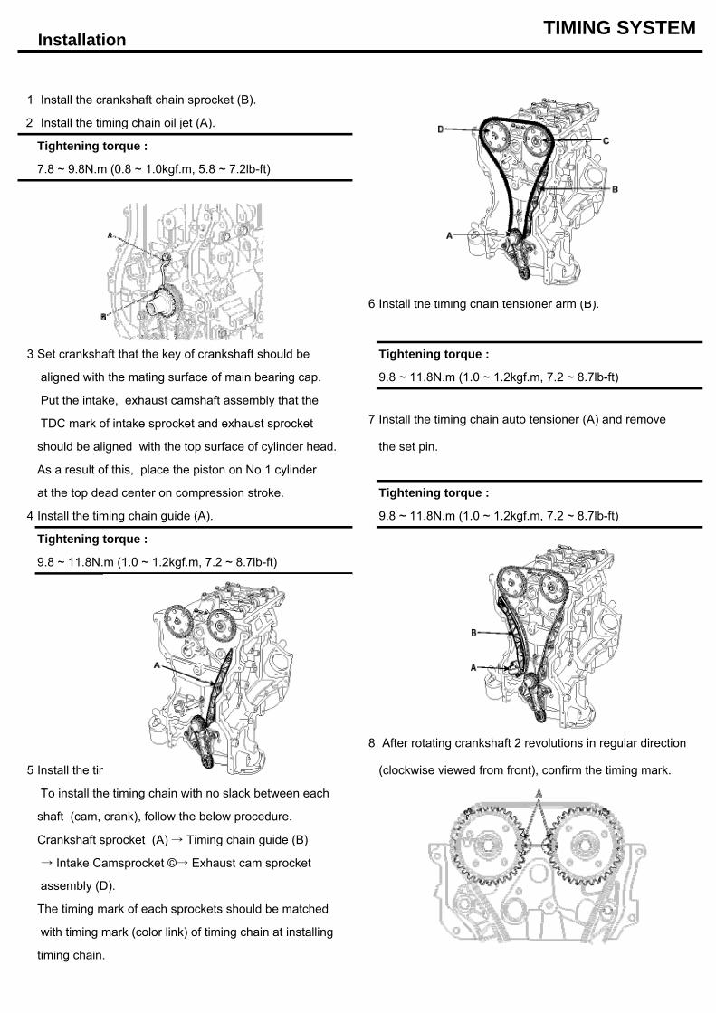
1 Install the crankshaft chain sprocket (B).
2 Install the timing chain oil jet (A).
Tightening torque :
7.8 ~ 9.8N.m (0.8 ~ 1.0kgf.m, 5.8 ~ 7.2lb-ft)
6 Install the timing chain tensioner arm (B).
3 Set crankshaft that the key of crankshaft should be Tightening torque :
aligned with the mating surface of main bearing cap. 9.8 ~ 11.8N.m (1.0 ~ 1.2kgf.m, 7.2 ~ 8.7lb-ft)
Put the intake, exhaust camshaft assembly that the
TDC mark of intake sprocket and exhaust sprocket 7 Install the timing chain auto tensioner (A) and remove
should be aligned with the top surface of cylinder head. the set pin.
As a result of this, place the piston on No.1 cylinder
at the top dead center on compression stroke. Tightening torque :
4 Install the timing chain guide (A). 9.8 ~ 11.8N.m (1.0 ~ 1.2kgf.m, 7.2 ~ 8.7lb-ft)
Tightening torque :
9.8 ~ 11.8N.m (1.0 ~ 1.2kgf.m, 7.2 ~ 8.7lb-ft)
8 After rotating crankshaft 2 revolutions in regular direction
5 Install the timing chain. (clockwise viewed from front), confirm the timing mark.
To install the timing chain with no slack between each
shaft (cam, crank), follow the below procedure.
Crankshaft sprocket (A) → Timing chain guide (B)
→ Intake Camsprocket ©→ Exhaust cam sprocket
assembly (D).
The timing mark of each sprockets should be matched
with timing mark (color link) of timing chain at installing
timing chain.
Installation TIMING SYSTEM
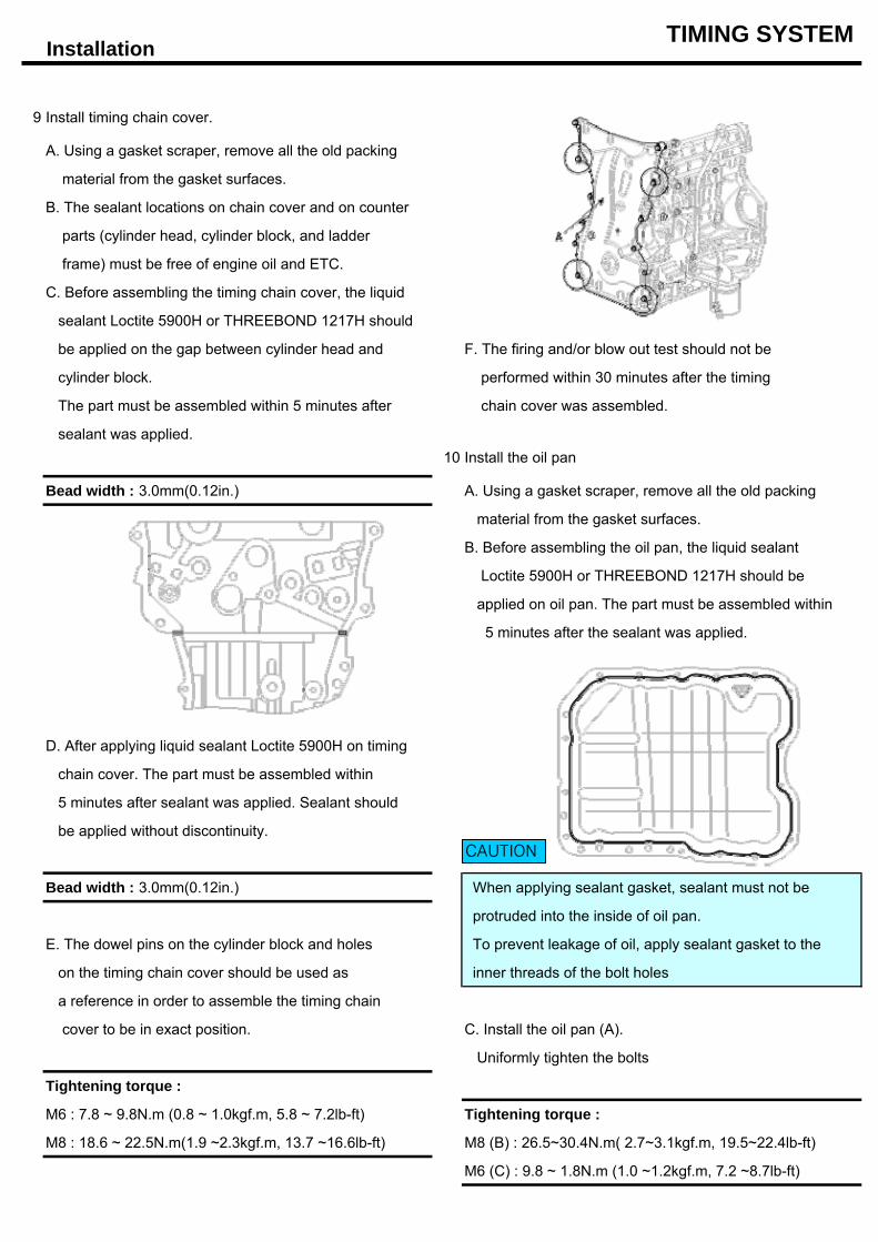
9 Install timing chain cover.
A. Using a gasket scraper, remove all the old packing
material from the gasket surfaces.
B. The sealant locations on chain cover and on counter
parts (cylinder head, cylinder block, and ladder
frame) must be free of engine oil and ETC.
C. Before assembling the timing chain cover, the liquid
sealant Loctite 5900H or THREEBOND 1217H should
be applied on the gap between cylinder head and F. The firing and/or blow out test should not be
cylinder block. performed within 30 minutes after the timing
The part must be assembled within 5 minutes after chain cover was assembled.
sealant was applied.10 Install the oil pan
Bead width : 3.0mm(0.12in.) A. Using a gasket scraper, remove all the old packing
material from the gasket surfaces.
B. Before assembling the oil pan, the liquid sealant
Loctite 5900H or THREEBOND 1217H should be
applied on oil pan. The part must be assembled within
5 minutes after the sealant was applied.
D. After applying liquid sealant Loctite 5900H on timing
chain cover. The part must be assembled within
5 minutes after sealant was applied. Sealant should
be applied without discontinuity.
Bead width : 3.0mm(0.12in.) When applying sealant gasket, sealant must not be
protruded into the inside of oil pan.
E. The dowel pins on the cylinder block and holes To prevent leakage of oil, apply sealant gasket to the
on the timing chain cover should be used as inner threads of the bolt holes
a reference in order to assemble the timing chain
cover to be in exact position. C. Install the oil pan (A).
Uniformly tighten the bolts
Tightening torque :
M6 : 7.8 ~ 9.8N.m (0.8 ~ 1.0kgf.m, 5.8 ~ 7.2lb-ft) Tightening torque :
M8 : 18.6 ~ 22.5N.m(1.9 ~2.3kgf.m, 13.7 ~16.6lb-ft) M8 (B) : 26.5~30.4N.m( 2.7~3.1kgf.m, 19.5~22.4lb-ft)
M6 (C) : 9.8 ~ 1.8N.m (1.0 ~1.2kgf.m, 7.2 ~8.7lb-ft)
CAUTION
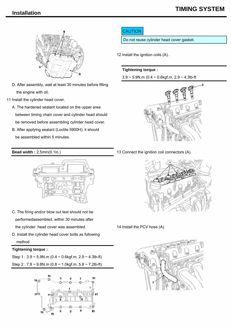
Installation TIMING SYSTEM
Do not reuse cylinder head cover gasket.
12 Install the ignition coils (A).
Tightening torque :
3.9 ~ 5.9N.m (0.4 ~ 0.6kgf.m, 2.9 ~ 4.3lb-ft
D. After assembly, wait at least 30 minutes before filling
the engine with oil.
11 Install the cylinder head cover.
A. The hardened sealant located on the upper area
between timing chain cover and cylinder head should
be removed before assembling cylinder head cover.
B. After applying sealant (Loctite 5900H), it should
be assembled within 5 minutes.
Bead width : 2.5mm(0.1in.) 13 Connect the ignition coil connectors (A).
C. The firing and/or blow out test should not be
performedassembled. within 30 minutes after
the cylinder head cover was assembled. 14 Install the PCV hose (A).
D. Install the cylinder head cover bolts as following
method
Tightening torque :
Step 1 : 3.9 ~ 5.9N.m (0.4 ~ 0.6kgf.m, 2.9 ~ 4.3lb-ft)
Step 2 : 7.8 ~ 9.8N.m (0.8 ~ 1.0kgf.m, 5.8 ~ 7.2lb-ft)
CAUTION
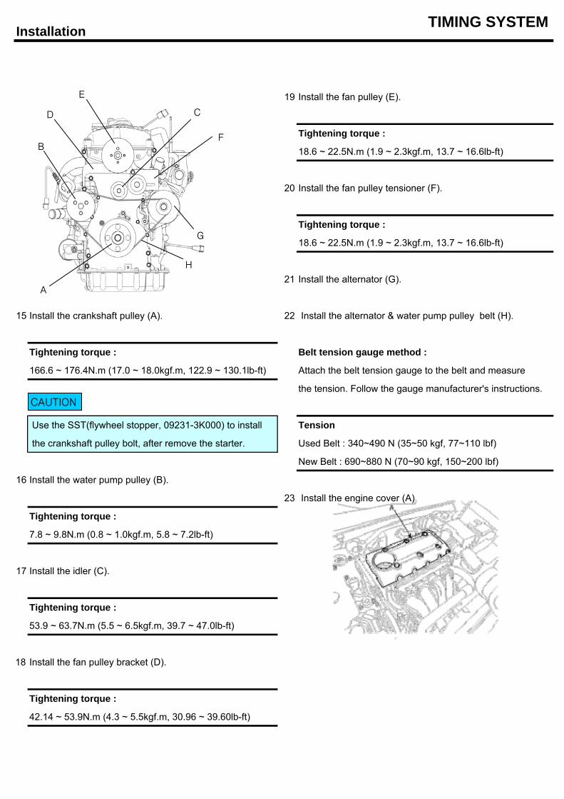
Installation TIMING SYSTEM
19 Install the fan pulley (E).
Tightening torque :
18.6 ~ 22.5N.m (1.9 ~ 2.3kgf.m, 13.7 ~ 16.6lb-ft)
20 Install the fan pulley tensioner (F).
Tightening torque :
18.6 ~ 22.5N.m (1.9 ~ 2.3kgf.m, 13.7 ~ 16.6lb-ft)
21 Install the alternator (G).
15 Install the crankshaft pulley (A). 22 Install the alternator & water pump pulley belt (H).
Tightening torque : Belt tension gauge method :
166.6 ~ 176.4N.m (17.0 ~ 18.0kgf.m, 122.9 ~ 130.1lb-ft) Attach the belt tension gauge to the belt and measure
the tension. Follow the gauge manufacturer's instructions.
Use the SST(flywheel stopper, 09231-3K000) to install Tension
the crankshaft pulley bolt, after remove the starter. Used Belt : 340~490 N (35~50 kgf, 77~110 lbf)
New Belt : 690~880 N (70~90 kgf, 150~200 lbf)
16 Install the water pump pulley (B).
23 Install the engine cover (A).
Tightening torque :
7.8 ~ 9.8N.m (0.8 ~ 1.0kgf.m, 5.8 ~ 7.2lb-ft)
17 Install the idler (C).
Tightening torque :
53.9 ~ 63.7N.m (5.5 ~ 6.5kgf.m, 39.7 ~ 47.0lb-ft)
18 Install the fan pulley bracket (D).
Tightening torque :
42.14 ~ 53.9N.m (4.3 ~ 5.5kgf.m, 30.96 ~ 39.60lb-ft)
CAUTION
A
B
CD
E
F
G
H
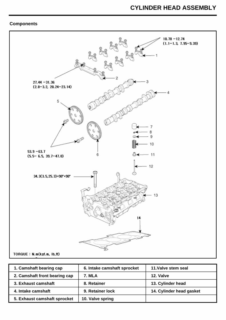
CYLINDER HEAD ASSEMBLY
Components
1. Camshaft bearing cap 6. Intake camshaft sprocket 11.Valve stem seal
2. Camshaft front bearing cap 7. MLA 12. Valve
3. Exhaust camshaft 8. Retainer 13. Cylinder head
4. Intake camshaft 9. Retainer lock 14. Cylinder head gasket
5. Exhaust camshaft sprocket 10. Valve spring
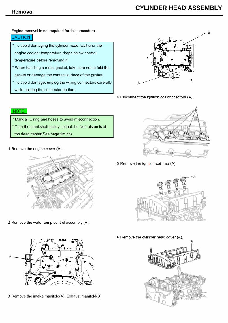
Removal CYLINDER HEAD ASSEMBLY
Engine removal is not required for this procedure
* To avoid damaging the cylinder head, wait until the
engine coolant temperature drops below normal
temperature before removing it.
* When handling a metal gasket, take care not to fold the
gasket or damage the contact surface of the gasket.
* To avoid damage, unplug the wiring connectors carefully
while holding the connector portion.
4 Disconnect the ignition coil connectors (A).
* Mark all wiring and hoses to avoid misconnection.
* Turn the crankshaft pulley so that the No1 piston is at
top dead center(See page timing)
1 Remove the engine cover (A).
5 Remove the ignition coil 4ea (A)
2 Remove the water temp control assembly (A).
6 Remove the cylinder head cover (A).
3 Remove the intake manifold(A), Exhaust manifold(B)
CAUTION
NOTE
A
A
B
Removal CYLINDER HEAD ASSEMBLY
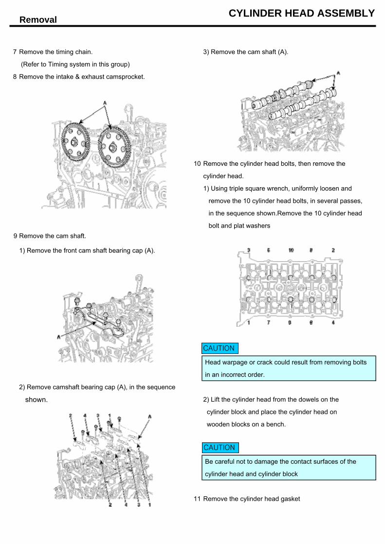
7 Remove the timing chain. 3) Remove the cam shaft (A).
(Refer to Timing system in this group)
8 Remove the intake & exhaust camsprocket.
10 Remove the cylinder head bolts, then remove the
cylinder head.
1) Using triple square wrench, uniformly loosen and
remove the 10 cylinder head bolts, in several passes,
in the sequence shown.Remove the 10 cylinder head
bolt and plat washers9 Remove the cam shaft.
1) Remove the front cam shaft bearing cap (A).
Head warpage or crack could result from removing bolts
in an incorrect order.
2) Remove camshaft bearing cap (A), in the sequence
shown. 2) Lift the cylinder head from the dowels on the
cylinder block and place the cylinder head on
wooden blocks on a bench.
Be careful not to damage the contact surfaces of the
cylinder head and cylinder block
11 Remove the cylinder head gasket
CAUTION
CAUTION
Disassembly / Inspection CYLINDER HEAD ASSEMBLY
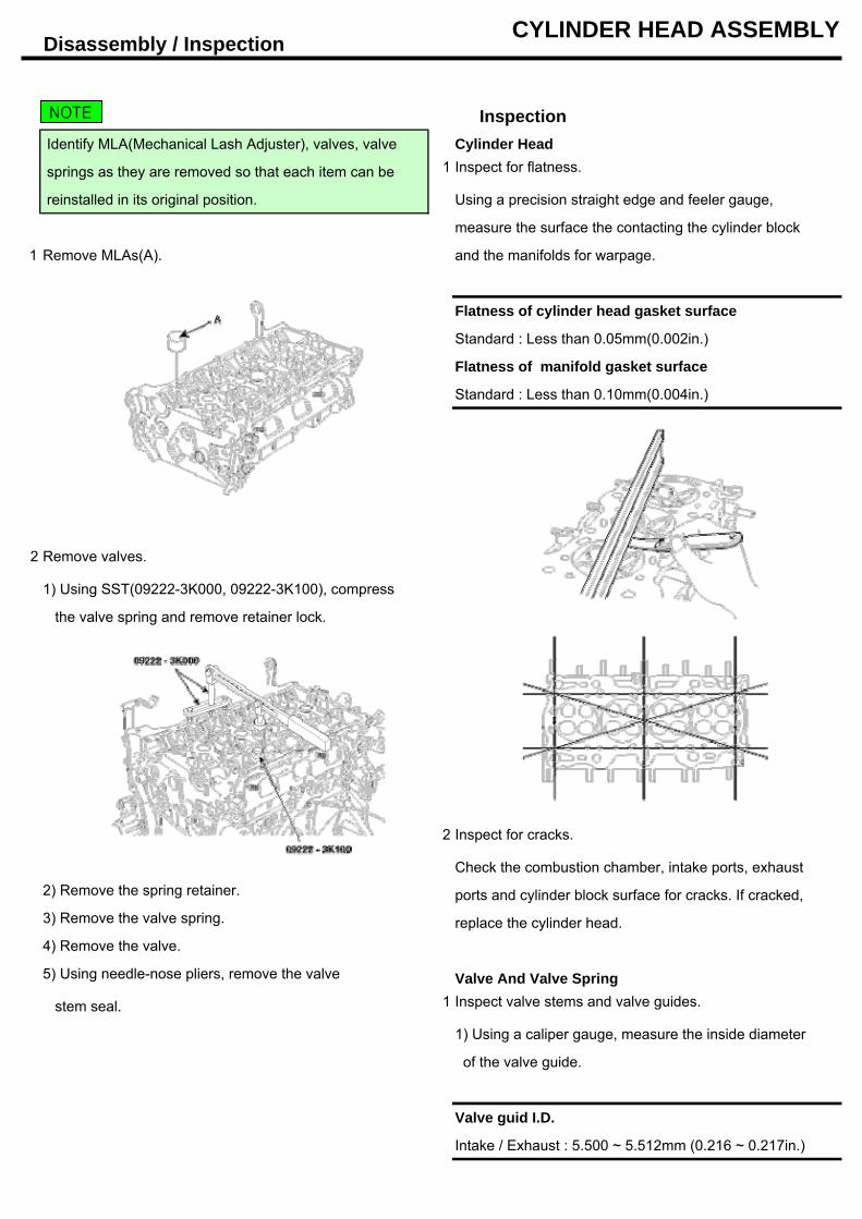
Inspection Identify MLA(Mechanical Lash Adjuster), valves, valve Cylinder Head
springs as they are removed so that each item can be 1 Inspect for flatness.
reinstalled in its original position. Using a precision straight edge and feeler gauge,
measure the surface the contacting the cylinder block
1 Remove MLAs(A). and the manifolds for warpage.
Flatness of cylinder head gasket surface
Standard : Less than 0.05mm(0.002in.)
Flatness of manifold gasket surface
Standard : Less than 0.10mm(0.004in.)
2 Remove valves.
1) Using SST(09222-3K000, 09222-3K100), compress
the valve spring and remove retainer lock.
2 Inspect for cracks.
Check the combustion chamber, intake ports, exhaust 2) Remove the spring retainer. ports and cylinder block surface for cracks. If cracked,3) Remove the valve spring. replace the cylinder head.4) Remove the valve.
5) Using needle-nose pliers, remove the valve Valve And Valve Spring
stem seal. 1 Inspect valve stems and valve guides.
1) Using a caliper gauge, measure the inside diameter
of the valve guide.
Valve guid I.D.
Intake / Exhaust : 5.500 ~ 5.512mm (0.216 ~ 0.217in.)
NOTE
Inspection CYLINDER HEAD ASSEMBLY
2 Inspect valves.
1) Check the valve is ground to the correct valve face angle.
2) Check that the surface of the valve for wear.
If the valve face is worn, replace the valve.3) Check the valve head margin thickness.
If the margin thickness is less than minimum,
replace the valve.
Margin
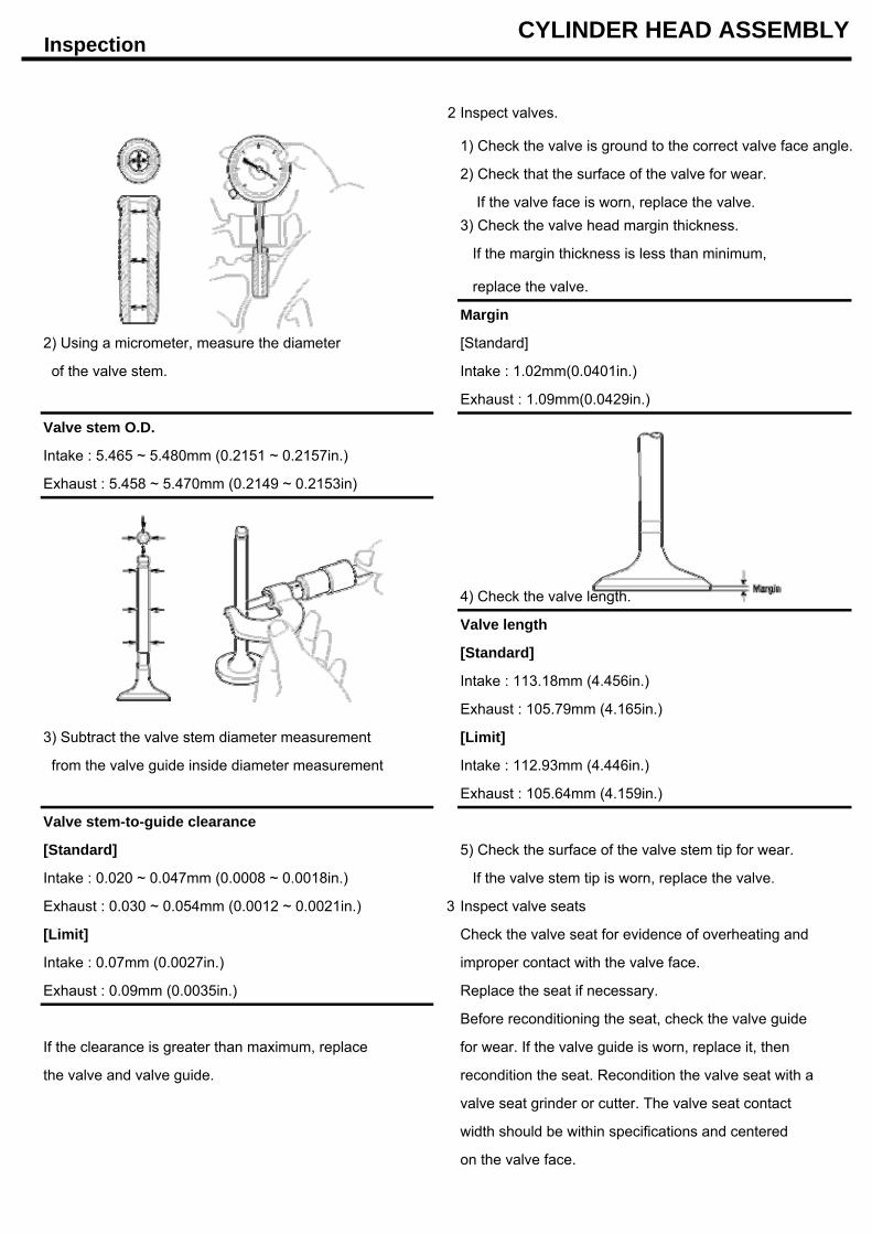
2) Using a micrometer, measure the diameter [Standard]
of the valve stem. Intake : 1.02mm(0.0401in.)
Exhaust : 1.09mm(0.0429in.)
Valve stem O.D.
Intake : 5.465 ~ 5.480mm (0.2151 ~ 0.2157in.)
Exhaust : 5.458 ~ 5.470mm (0.2149 ~ 0.2153in)
4) Check the valve length.
Valve length
[Standard]
Intake : 113.18mm (4.456in.)
Exhaust : 105.79mm (4.165in.)
3) Subtract the valve stem diameter measurement [Limit]
from the valve guide inside diameter measurement Intake : 112.93mm (4.446in.)
Exhaust : 105.64mm (4.159in.)
Valve stem-to-guide clearance
[Standard] 5) Check the surface of the valve stem tip for wear.
Intake : 0.020 ~ 0.047mm (0.0008 ~ 0.0018in.) If the valve stem tip is worn, replace the valve.
Exhaust : 0.030 ~ 0.054mm (0.0012 ~ 0.0021in.) 3 Inspect valve seats
[Limit] Check the valve seat for evidence of overheating and
Intake : 0.07mm (0.0027in.) improper contact with the valve face.
Exhaust : 0.09mm (0.0035in.) Replace the seat if necessary.
Before reconditioning the seat, check the valve guide
If the clearance is greater than maximum, replace for wear. If the valve guide is worn, replace it, then
the valve and valve guide. recondition the seat. Recondition the valve seat with a
valve seat grinder or cutter. The valve seat contact
width should be within specifications and centered
on the valve face.
Inspection CYLINDER HEAD ASSEMBLY
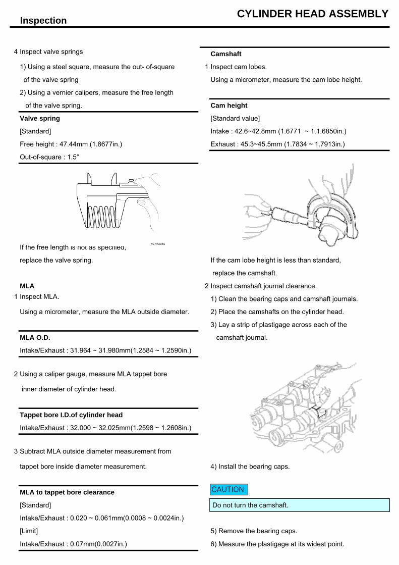
4 Inspect valve springs Camshaft
1) Using a steel square, measure the out- of-square 1 Inspect cam lobes.
of the valve spring Using a micrometer, measure the cam lobe height.
2) Using a vernier calipers, measure the free length
of the valve spring. Cam height
Valve spring [Standard value]
[Standard] Intake : 42.6~42.8mm (1.6771 ~ 1.1.6850in.)
Free height : 47.44mm (1.8677in.) Exhaust : 45.3~45.5mm (1.7834 ~ 1.7913in.)
Out-of-square : 1.5°
If the free length is not as specified,
replace the valve spring. If the cam lobe height is less than standard,
replace the camshaft.
MLA 2 Inspect camshaft journal clearance.1 Inspect MLA. 1) Clean the bearing caps and camshaft journals.
Using a micrometer, measure the MLA outside diameter. 2) Place the camshafts on the cylinder head.
3) Lay a strip of plastigage across each of the
MLA O.D. camshaft journal.
Intake/Exhaust : 31.964 ~ 31.980mm(1.2584 ~ 1.2590in.)
2 Using a caliper gauge, measure MLA tappet bore
inner diameter of cylinder head.
Tappet bore I.D.of cylinder head
Intake/Exhaust : 32.000 ~ 32.025mm(1.2598 ~ 1.2608in.)
Subtract MLA outside diameter measurement from
tappet bore inside diameter measurement. 4) Install the bearing caps.
MLA to tappet bore clearance
[Standard] Do not turn the camshaft.
Intake/Exhaust : 0.020 ~ 0.061mm(0.0008 ~ 0.0024in.)
[Limit] 5) Remove the bearing caps.
Intake/Exhaust : 0.07mm(0.0027in.) 6) Measure the plastigage at its widest point.
3
CAUTION
InspectionCYLINDER HEAD ASSEMBLY
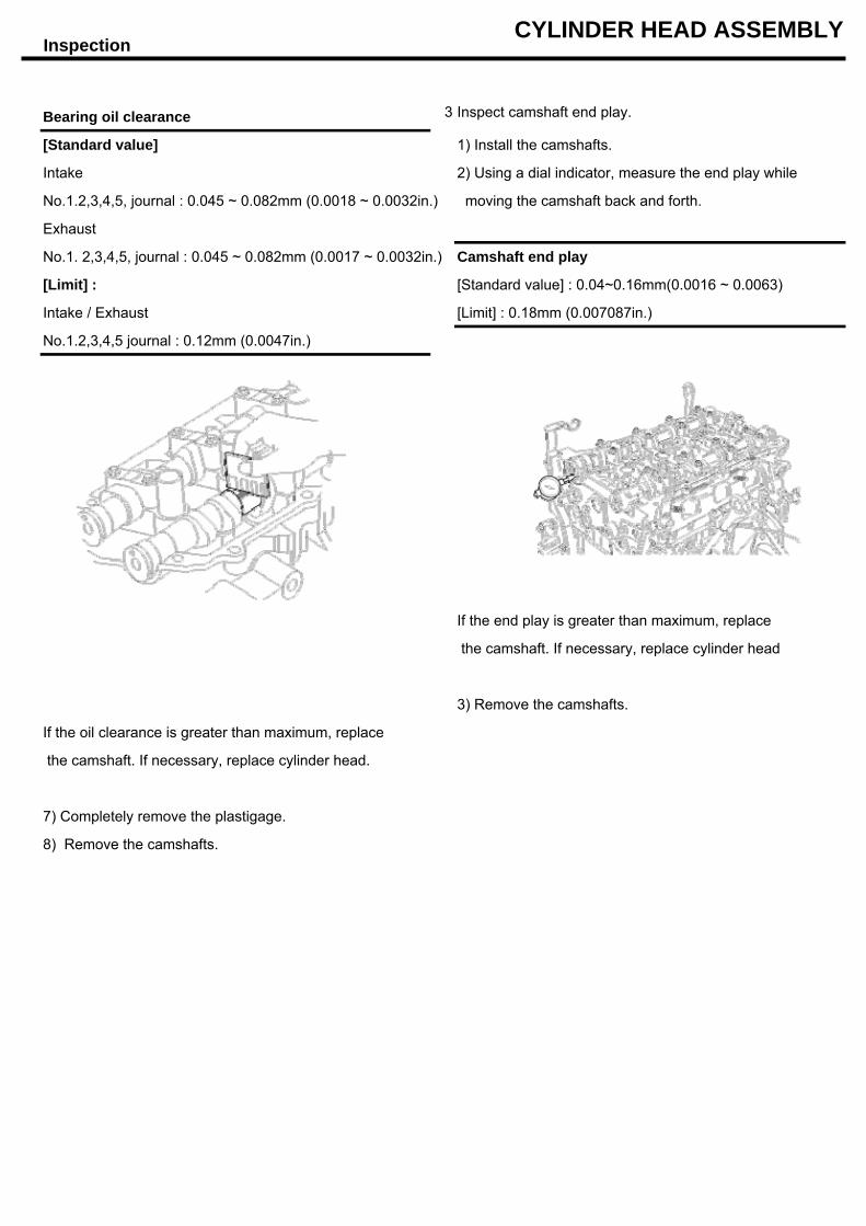
Bearing oil clearance 3 Inspect camshaft end play.
[Standard value] 1) Install the camshafts.
Intake 2) Using a dial indicator, measure the end play while
No.1.2,3,4,5, journal : 0.045 ~ 0.082mm (0.0018 ~ 0.0032in.) moving the camshaft back and forth.
Exhaust
No.1. 2,3,4,5, journal : 0.045 ~ 0.082mm (0.0017 ~ 0.0032in.) Camshaft end play
[Limit] : [Standard value] : 0.04~0.16mm(0.0016 ~ 0.0063)
Intake / Exhaust [Limit] : 0.18mm (0.007087in.)
No.1.2,3,4,5 journal : 0.12mm (0.0047in.)
If the end play is greater than maximum, replace
the camshaft. If necessary, replace cylinder head
3) Remove the camshafts.
If the oil clearance is greater than maximum, replace
the camshaft. If necessary, replace cylinder head.
7) Completely remove the plastigage.
8) Remove the camshafts.
Reassembly CYLINDER HEAD ASSEMBLY
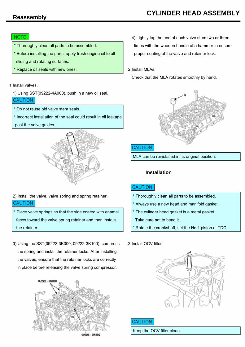
4) Lightly tap the end of each valve stem two or three
* Thoroughly clean all parts to be assembled. times with the wooden handle of a hammer to ensure
* Before installing the parts, apply fresh engine oil to all proper seating of the valve and retainer lock.
sliding and rotating surfaces.
* Replace oil seals with new ones. 2 Install MLAs.
Check that the MLA rotates smoothly by hand.
1 Install valves.
1) Using SST(09222-4A000), push in a new oil seal.
* Do not reuse old valve stem seals.
* Incorrect installation of the seal could result in oil leakage
past the valve guides.
MLA can be reinstalled in its original position.
Installation
2) Install the valve, valve spring and spring retainer. * Thoroughly clean all parts to be assembled.
* Always use a new head and manifold gasket.
* Place valve springs so that the side coated with enamel * The cylinder head gasket is a metal gasket.
faces toward the valve spring retainer and then installs Take care not to bend it.
the retainer. * Rotate the crankshaft, set the No.1 piston at TDC.
3) Using the SST(09222-3K000, 09222-3K100), compress 3 Install OCV filter
the spring and install the retainer locks. After installing
the valves, ensure that the retainer locks are correctly
in place before releasing the valve spring compressor.
Keep the OCV filter clean.
NOTE
CAUTION
CAUTION
CAUTION
CAUTION
CAUTION
Installation CYLINDER HEAD ASSEMBLY
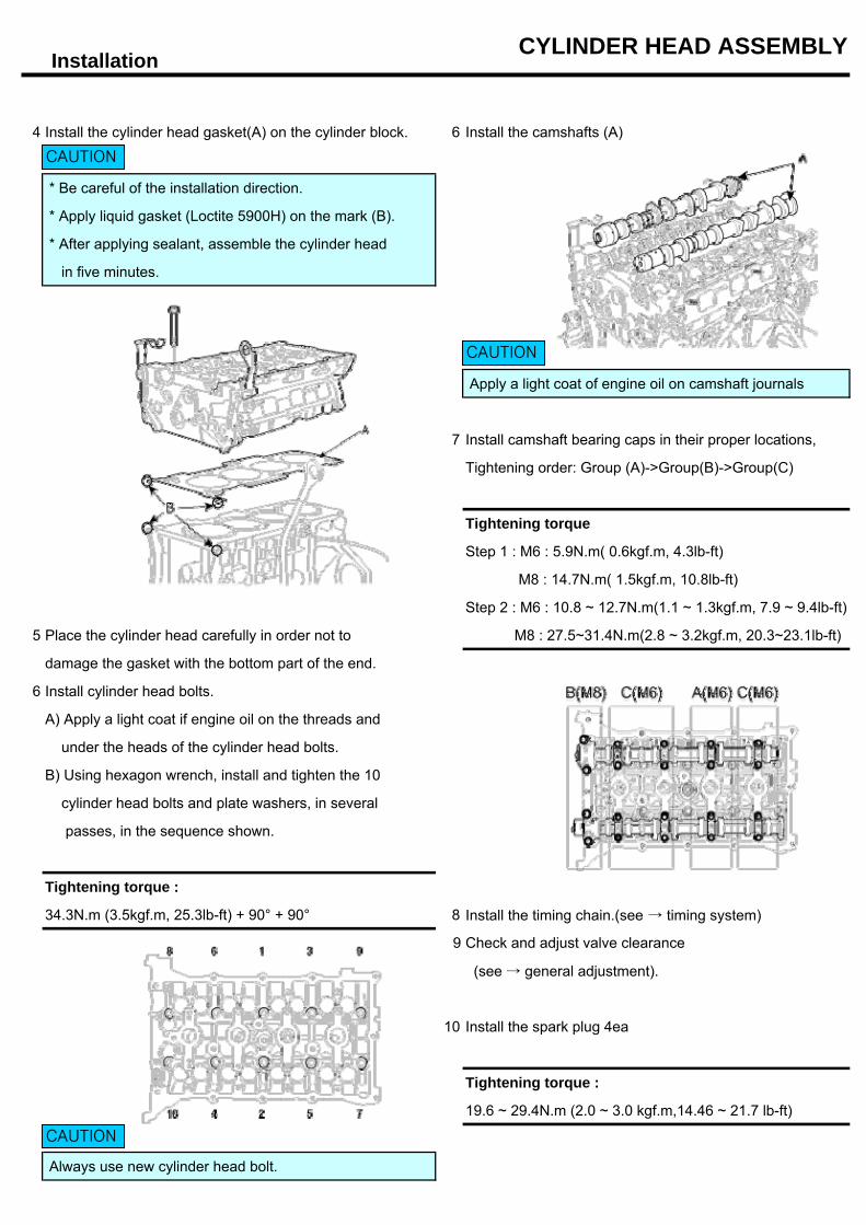
4 Install the cylinder head gasket(A) on the cylinder block. 6 Install the camshafts (A)
* Be careful of the installation direction.
* Apply liquid gasket (Loctite 5900H) on the mark (B).
* After applying sealant, assemble the cylinder head
in five minutes.
Apply a light coat of engine oil on camshaft journals
7 Install camshaft bearing caps in their proper locations,
Tightening order: Group (A)->Group(B)->Group(C)
Tightening torque
Step 1 : M6 : 5.9N.m( 0.6kgf.m, 4.3lb-ft)
M8 : 14.7N.m( 1.5kgf.m, 10.8lb-ft)
Step 2 : M6 : 10.8 ~ 12.7N.m(1.1 ~ 1.3kgf.m, 7.9 ~ 9.4lb-ft)
5 Place the cylinder head carefully in order not to M8 : 27.5~31.4N.m(2.8 ~ 3.2kgf.m, 20.3~23.1lb-ft)
damage the gasket with the bottom part of the end.
6 Install cylinder head bolts.
A) Apply a light coat if engine oil on the threads and
under the heads of the cylinder head bolts.
B) Using hexagon wrench, install and tighten the 10
cylinder head bolts and plate washers, in several
passes, in the sequence shown.
Tightening torque :
34.3N.m (3.5kgf.m, 25.3lb-ft) + 90° + 90° 8 Install the timing chain.(see → timing system)
9 Check and adjust valve clearance
(see → general adjustment).
10 Install the spark plug 4ea
Tightening torque :
19.6 ~ 29.4N.m (2.0 ~ 3.0 kgf.m,14.46 ~ 21.7 lb-ft)
Always use new cylinder head bolt.
CAUTION
CAUTION
CAUTION
Installation CYLINDER HEAD ASSEMBLY
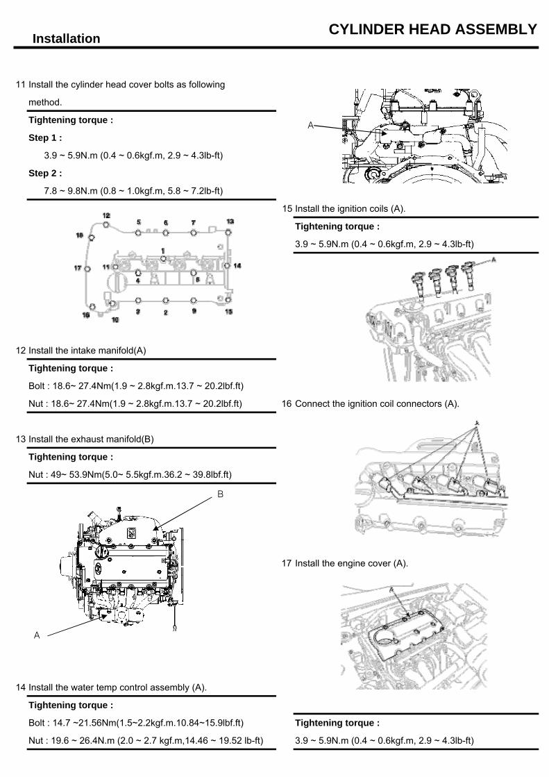
11 Install the cylinder head cover bolts as following
method.
Tightening torque :
Step 1 :
3.9 ~ 5.9N.m (0.4 ~ 0.6kgf.m, 2.9 ~ 4.3lb-ft)
Step 2 :
7.8 ~ 9.8N.m (0.8 ~ 1.0kgf.m, 5.8 ~ 7.2lb-ft)
15 Install the ignition coils (A).
Tightening torque :
3.9 ~ 5.9N.m (0.4 ~ 0.6kgf.m, 2.9 ~ 4.3lb-ft)
12 Install the intake manifold(A)
Tightening torque :
Bolt : 18.6~ 27.4Nm(1.9 ~ 2.8kgf.m.13.7 ~ 20.2lbf.ft)
Nut : 18.6~ 27.4Nm(1.9 ~ 2.8kgf.m.13.7 ~ 20.2lbf.ft) 16 Connect the ignition coil connectors (A).
13 Install the exhaust manifold(B)
Tightening torque :
Nut : 49~ 53.9Nm(5.0~ 5.5kgf.m.36.2 ~ 39.8lbf.ft)
17 Install the engine cover (A).
14 Install the water temp control assembly (A).
Tightening torque :
Bolt : 14.7 ~21.56Nm(1.5~2.2kgf.m.10.84~15.9lbf.ft) Tightening torque :
Nut : 19.6 ~ 26.4N.m (2.0 ~ 2.7 kgf.m,14.46 ~ 19.52 lb-ft) 3.9 ~ 5.9N.m (0.4 ~ 0.6kgf.m, 2.9 ~ 4.3lb-ft)
A
B
A
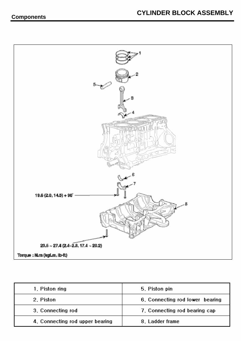
Components CYLINDER BLOCK ASSEMBLY
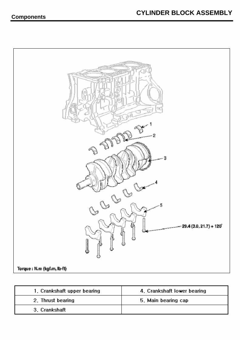
Components CYLINDER BLOCK ASSEMBLY
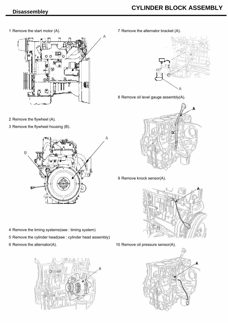
Disassembley CYLINDER BLOCK ASSEMBLY
1 Remove the start motor (A). 7 Remove the alternator bracket (A).
8 Remove oil level gauge assembly(A).
2 Remove the flywheel (A).
3 Remove the flywheel housing (B).
9 Remove knock sensor(A).
4 Remove the timing systems(see : timing system)
5 Remove the cylinder head(see : cylinder head assembly)
6 Remove the alternator(A). 10 Remove oil pressure sensor(A).
A
B
A
A
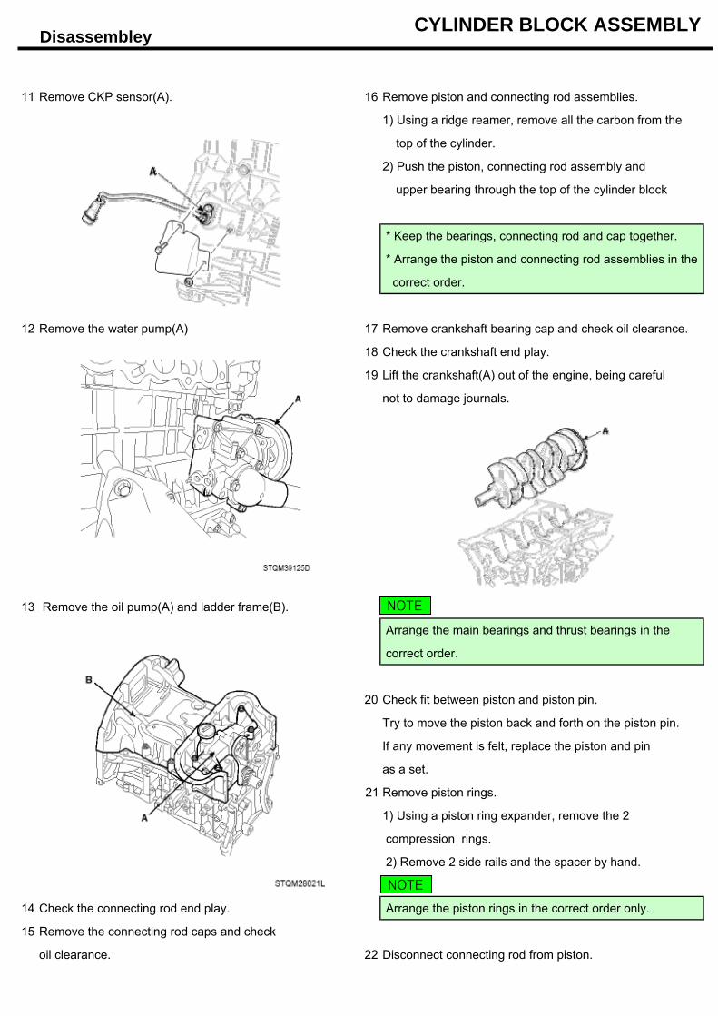
Disassembley CYLINDER BLOCK ASSEMBLY
11 Remove CKP sensor(A). 16 Remove piston and connecting rod assemblies.
1) Using a ridge reamer, remove all the carbon from the
top of the cylinder.
2) Push the piston, connecting rod assembly and
upper bearing through the top of the cylinder block
* Keep the bearings, connecting rod and cap together.
* Arrange the piston and connecting rod assemblies in the
correct order.
12 Remove the water pump(A) 17 Remove crankshaft bearing cap and check oil clearance.
18 Check the crankshaft end play.
19 Lift the crankshaft(A) out of the engine, being careful
not to damage journals.
13 Remove the oil pump(A) and ladder frame(B).
Arrange the main bearings and thrust bearings in the
correct order.
20 Check fit between piston and piston pin.
Try to move the piston back and forth on the piston pin.
If any movement is felt, replace the piston and pin
as a set.
21 Remove piston rings.
1) Using a piston ring expander, remove the 2
compression rings.
2) Remove 2 side rails and the spacer by hand.
14 Check the connecting rod end play. Arrange the piston rings in the correct order only.
15 Remove the connecting rod caps and check
oil clearance. 22 Disconnect connecting rod from piston.
NOTE
NOTE
Inspection CYLINDER BLOCK ASSEMBLY
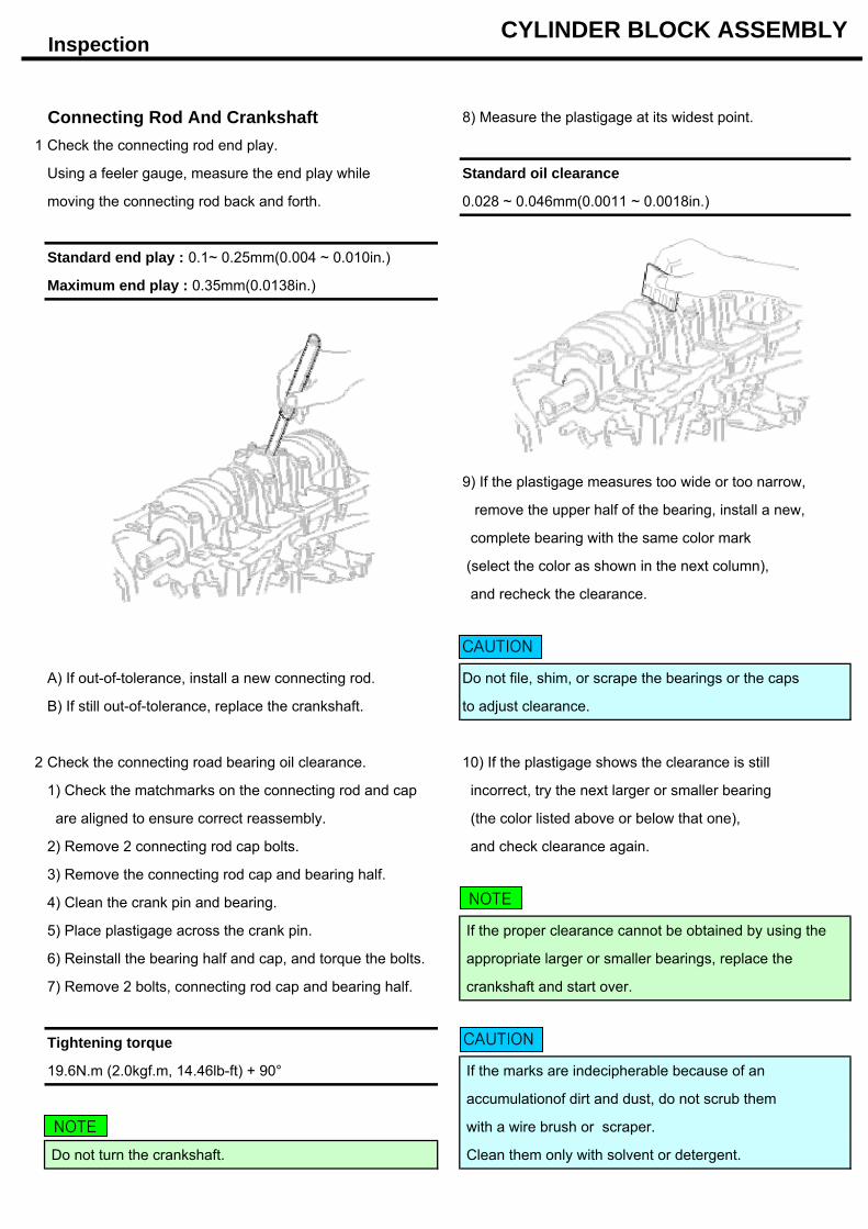
Connecting Rod And Crankshaft 8) Measure the plastigage at its widest point.
1 Check the connecting rod end play.
Using a feeler gauge, measure the end play while Standard oil clearance
moving the connecting rod back and forth. 0.028 ~ 0.046mm(0.0011 ~ 0.0018in.)
Standard end play : 0.1~ 0.25mm(0.004 ~ 0.010in.)
Maximum end play : 0.35mm(0.0138in.)
9) If the plastigage measures too wide or too narrow,
remove the upper half of the bearing, install a new,
complete bearing with the same color mark
(select the color as shown in the next column),
and recheck the clearance.
A) If out-of-tolerance, install a new connecting rod. Do not file, shim, or scrape the bearings or the caps
B) If still out-of-tolerance, replace the crankshaft. to adjust clearance.
2 Check the connecting road bearing oil clearance. 10) If the plastigage shows the clearance is still
1) Check the matchmarks on the connecting rod and cap incorrect, try the next larger or smaller bearing
are aligned to ensure correct reassembly. (the color listed above or below that one),
2) Remove 2 connecting rod cap bolts. and check clearance again.
3) Remove the connecting rod cap and bearing half.
4) Clean the crank pin and bearing.
5) Place plastigage across the crank pin. If the proper clearance cannot be obtained by using the
6) Reinstall the bearing half and cap, and torque the bolts. appropriate larger or smaller bearings, replace the
7) Remove 2 bolts, connecting rod cap and bearing half. crankshaft and start over.
Tightening torque
19.6N.m (2.0kgf.m, 14.46lb-ft) + 90° If the marks are indecipherable because of an
accumulationof dirt and dust, do not scrub them
with a wire brush or scraper.
Do not turn the crankshaft. Clean them only with solvent or detergent.
NOTE
CAUTION
NOTE
CAUTION
Inspection CYLINDER BLOCK ASSEMBLY
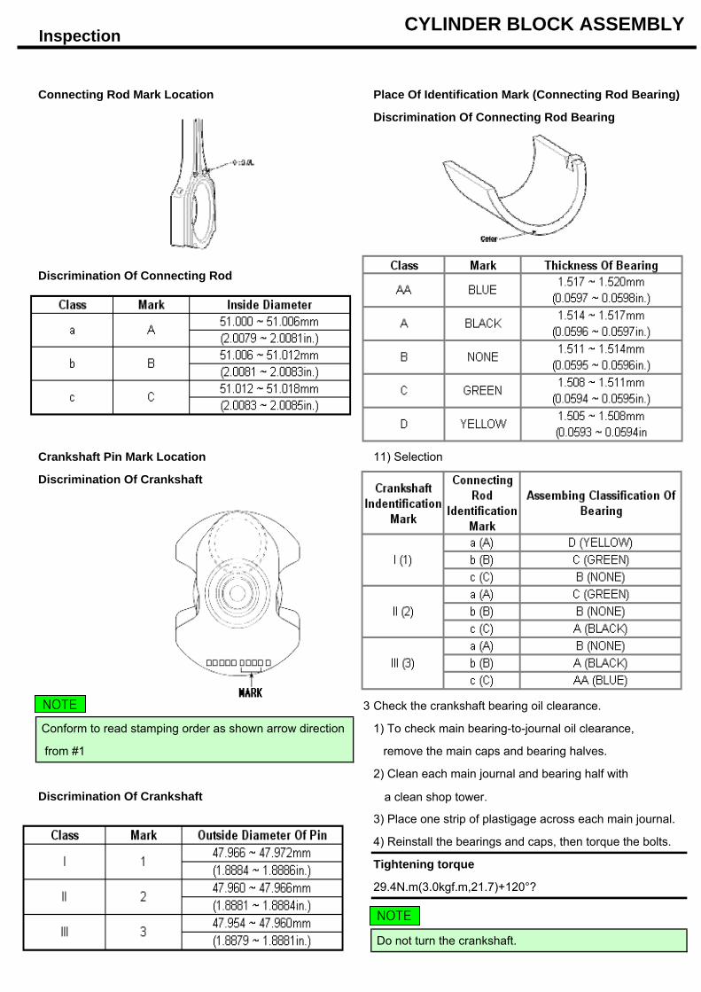
Connecting Rod Mark Location Place Of Identification Mark (Connecting Rod Bearing)
Discrimination Of Connecting Rod Bearing
Discrimination Of Connecting Rod
Crankshaft Pin Mark Location 11) Selection
Discrimination Of Crankshaft
3 Check the crankshaft bearing oil clearance.
Conform to read stamping order as shown arrow direction 1) To check main bearing-to-journal oil clearance,
from #1 remove the main caps and bearing halves.
2) Clean each main journal and bearing half with
Discrimination Of Crankshaft a clean shop tower.
3) Place one strip of plastigage across each main journal.
4) Reinstall the bearings and caps, then torque the bolts.
Tightening torque
29.4N.m(3.0kgf.m,21.7)+120°?
Do not turn the crankshaft.
NOTE
NOTE
Inspection CYLINDER BLOCK ASSEMBLY
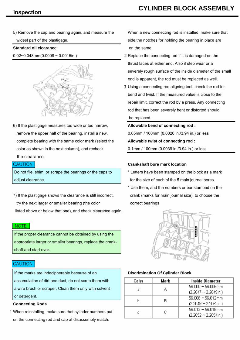
5) Remove the cap and bearing again, and measure the When a new connecting rod is installed, make sure that
widest part of the plastigage. side.the notches for holding the bearing in place are
Standard oil clearance on the same
0.02~0.048mm(0.0008 ~ 0.0015in.) 2 Replace the connecting rod if it is damaged on the
thrust faces at either end. Also if step wear or a
severely rough surface of the inside diameter of the small
end is apparent, the rod must be replaced as well.
3 Using a connecting rod aligning tool, check the rod for
bend and twist. If the measured value is close to the
repair limit, correct the rod by a press. Any connecting
rod that has been severely bent or distorted should
be replaced.
6) If the plastigage measures too wide or too narrow, Allowable bend of connecting rod :
remove the upper half of the bearing, install a new, 0.05mm / 100mm (0.0020 in./3.94 in.) or less
complete bearing with the same color mark (select the Allowable twist of connecting rod :
color as shown in the next column), and recheck 0.1mm / 100mm (0.0039 in./3.94 in.) or less
the clearance.
Crankshaft bore mark location
Do not file, shim, or scrape the bearings or the caps to * Letters have been stamped on the block as a mark
adjust clearance. for the size of each of the 5 main journal bores.
* Use them, and the numbers or bar stamped on the
7) If the plastigage shows the clearance is still incorrect, crank (marks for main journal size), to choose the
try the next larger or smaller bearing (the color correct bearings
listed above or below that one), and check clearance again.
If the proper clearance cannot be obtained by using the
appropriate larger or smaller bearings, replace the crank-
shaft and start over.
If the marks are indecipherable because of an Discrimination Of Cylinder Block
accumulation of dirt and dust, do not scrub them with
a wire brush or scraper. Clean them only with solvent
or detergent.
Connecting Rods
1 When reinstalling, make sure that cylinder numbers put
on the connecting rod and cap at disassembly match.
CAUTION
NOTE
CAUTION
Inspection CYLINDER BLOCK ASSEMBLY
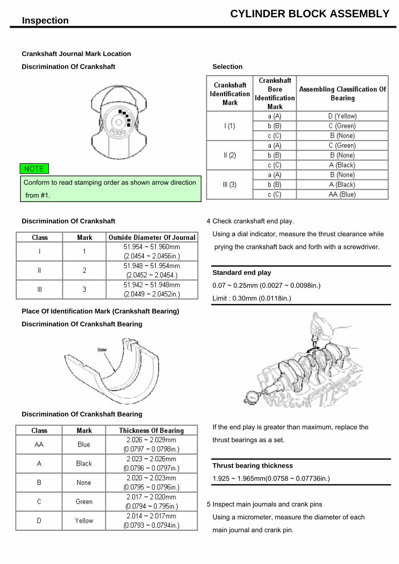
Crankshaft Journal Mark Location
Discrimination Of Crankshaft Selection
Conform to read stamping order as shown arrow direction
from #1.
Discrimination Of Crankshaft 4 Check crankshaft end play.
Using a dial indicator, measure the thrust clearance while
prying the crankshaft back and forth with a screwdriver.
Standard end play
0.07 ~ 0.25mm (0.0027 ~ 0.0098in.)
Limit : 0.30mm (0.0118in.)
Place Of Identification Mark (Crankshaft Bearing)
Discrimination Of Crankshaft Bearing
Discrimination Of Crankshaft Bearing
If the end play is greater than maximum, replace the
thrust bearings as a set.
Thrust bearing thickness
1.925 ~ 1.965mm(0.0758 ~ 0.07736in.)
5 Inspect main journals and crank pins
Using a micrometer, measure the diameter of each
main journal and crank pin.
NOTE
Inspection CYLINDER BLOCK ASSEMBLY
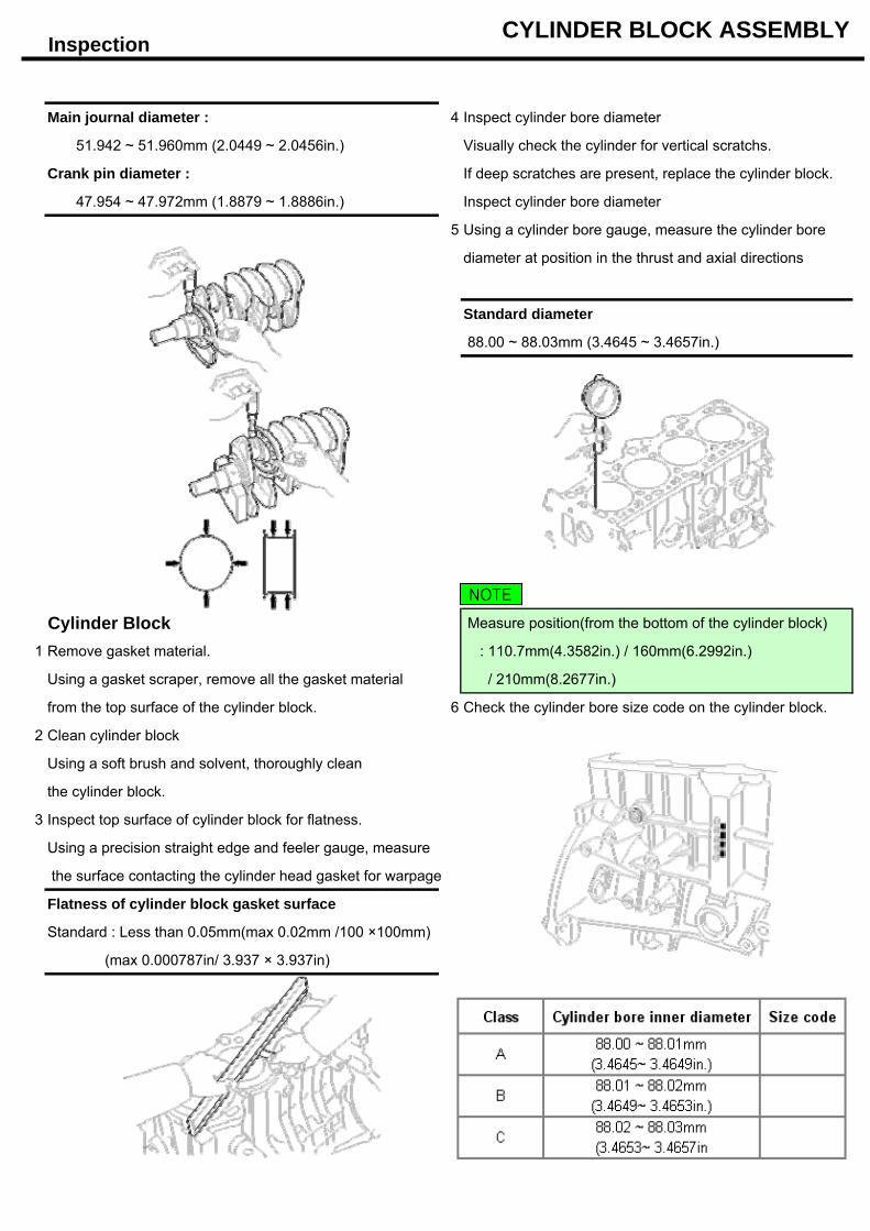
Main journal diameter : 4 Inspect cylinder bore diameter
51.942 ~ 51.960mm (2.0449 ~ 2.0456in.) Visually check the cylinder for vertical scratchs.
Crank pin diameter : If deep scratches are present, replace the cylinder block.
47.954 ~ 47.972mm (1.8879 ~ 1.8886in.) Inspect cylinder bore diameter
5 Using a cylinder bore gauge, measure the cylinder bore
diameter at position in the thrust and axial directions
Standard diameter
88.00 ~ 88.03mm (3.4645 ~ 3.4657in.)
Cylinder Block Measure position(from the bottom of the cylinder block)
1 Remove gasket material. : 110.7mm(4.3582in.) / 160mm(6.2992in.)
Using a gasket scraper, remove all the gasket material / 210mm(8.2677in.)
from the top surface of the cylinder block. 6 Check the cylinder bore size code on the cylinder block.
2 Clean cylinder block
Using a soft brush and solvent, thoroughly clean
the cylinder block.
3 Inspect top surface of cylinder block for flatness.
Using a precision straight edge and feeler gauge, measure
the surface contacting the cylinder head gasket for warpage
Flatness of cylinder block gasket surface
Standard : Less than 0.05mm(max 0.02mm /100 ×100mm)
(max 0.000787in/ 3.937 × 3.937in)
NOTE
Inspection CYLINDER BLOCK ASSEMBLY
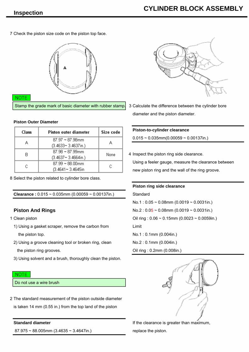
7 Check the piston size code on the piston top face.
Stamp the grade mark of basic diameter with rubber stamp. 3 Calculate the difference between the cylinder bore
diameter and the piston diameter.
Piston Outer Diameter
Piston-to-cylinder clearance
0.015 ~ 0.035mm(0.00059 ~ 0.00137in.)
4 Inspect the piston ring side clearance.
Using a feeler gauge, measure the clearance between
new piston ring and the wall of the ring groove.
8 Select the piston related to cylinder bore class.
Piston ring side clearance
Clearance : 0.015 ~ 0.035mm (0.00059 ~ 0.00137in.) Standard
No.1 : 0.05 ~ 0.08mm (0.0019 ~ 0.0031in.)
Piston And Rings No.2 : 0.05 ~ 0.08mm (0.0019 ~ 0.0031in.)
1 Clean piston Oil ring : 0.06 ~ 0.15mm (0.0023 ~ 0.0059in.)
1) Using a gasket scraper, remove the carbon from Limit
the piston top. No.1 : 0.1mm (0.004in.)
2) Using a groove cleaning tool or broken ring, clean No.2 : 0.1mm (0.004in.)
the piston ring grooves. Oil ring : 0.2mm (0.008in.)
3) Using solvent and a brush, thoroughly clean the piston.
Do not use a wire brush
2 The standard measurement of the piston outside diameter
is taken 14 mm (0.55 in.) from the top land of the piston
Standard diameter If the clearance is greater than maximum,
87.975 ~ 88.005mm (3.4635 ~ 3.4647in.) replace the piston.
NOTE
NOTE
Inspection CYLINDER BLOCK ASSEMBLY
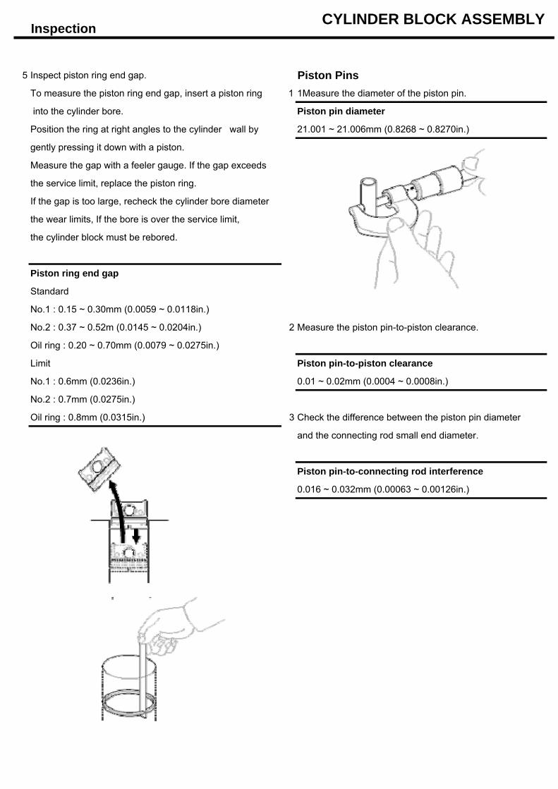
5 Inspect piston ring end gap. Piston PinsTo measure the piston ring end gap, insert a piston ring 1 1Measure the diameter of the piston pin.
into the cylinder bore. Piston pin diameter
Position the ring at right angles to the cylinder wall by 21.001 ~ 21.006mm (0.8268 ~ 0.8270in.)
gently pressing it down with a piston.
Measure the gap with a feeler gauge. If the gap exceeds
the service limit, replace the piston ring.
If the gap is too large, recheck the cylinder bore diameter
the wear limits, If the bore is over the service limit,
the cylinder block must be rebored.
Piston ring end gap
Standard
No.1 : 0.15 ~ 0.30mm (0.0059 ~ 0.0118in.)
No.2 : 0.37 ~ 0.52m (0.0145 ~ 0.0204in.) 2 Measure the piston pin-to-piston clearance.
Oil ring : 0.20 ~ 0.70mm (0.0079 ~ 0.0275in.)
Limit Piston pin-to-piston clearance
No.1 : 0.6mm (0.0236in.) 0.01 ~ 0.02mm (0.0004 ~ 0.0008in.)
No.2 : 0.7mm (0.0275in.)
Oil ring : 0.8mm (0.0315in.) 3 Check the difference between the piston pin diameter
and the connecting rod small end diameter.
Piston pin-to-connecting rod interference
0.016 ~ 0.032mm (0.00063 ~ 0.00126in.)
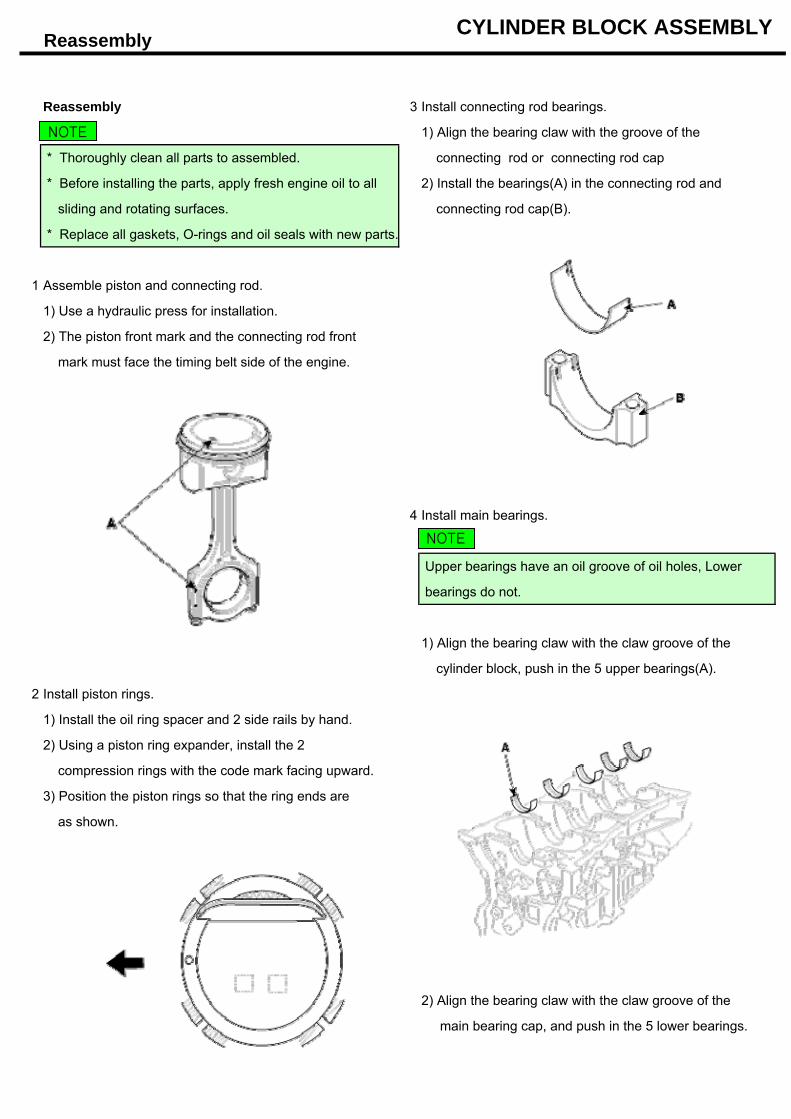
Reassembly CYLINDER BLOCK ASSEMBLY
Reassembly 3 Install connecting rod bearings.
1) Align the bearing claw with the groove of the
* Thoroughly clean all parts to assembled. connecting rod or connecting rod cap
* Before installing the parts, apply fresh engine oil to all 2) Install the bearings(A) in the connecting rod and
sliding and rotating surfaces. connecting rod cap(B).
* Replace all gaskets, O-rings and oil seals with new parts.
1 Assemble piston and connecting rod.
1) Use a hydraulic press for installation.
2) The piston front mark and the connecting rod front
mark must face the timing belt side of the engine.
4 Install main bearings.
Upper bearings have an oil groove of oil holes, Lower
bearings do not.
1) Align the bearing claw with the claw groove of the
cylinder block, push in the 5 upper bearings(A).
2 Install piston rings.
1) Install the oil ring spacer and 2 side rails by hand.
2) Using a piston ring expander, install the 2
compression rings with the code mark facing upward.
3) Position the piston rings so that the ring ends are
as shown.
2) Align the bearing claw with the claw groove of the
main bearing cap, and push in the 5 lower bearings.
NOTE
NOTE
Disassembley/ Reassembly CYLINDER BLOCK ASSEMBLY
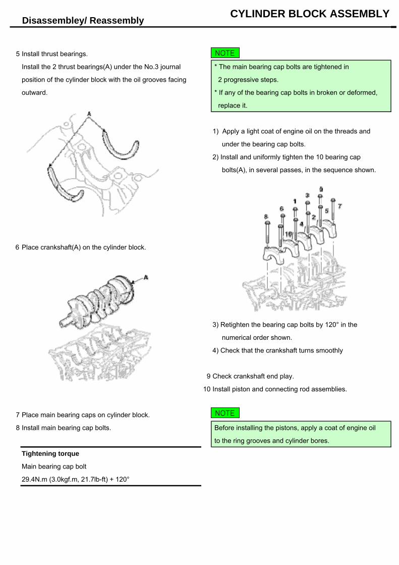
5 Install thrust bearings.
Install the 2 thrust bearings(A) under the No.3 journal * The main bearing cap bolts are tightened in
position of the cylinder block with the oil grooves facing 2 progressive steps.
outward. * If any of the bearing cap bolts in broken or deformed,
replace it.
1) Apply a light coat of engine oil on the threads and
under the bearing cap bolts.
2) Install and uniformly tighten the 10 bearing cap
bolts(A), in several passes, in the sequence shown.
6 Place crankshaft(A) on the cylinder block.
3) Retighten the bearing cap bolts by 120° in the
numerical order shown.
4) Check that the crankshaft turns smoothly
9 Check crankshaft end play.
10 Install piston and connecting rod assemblies.
7 Place main bearing caps on cylinder block.
8 Install main bearing cap bolts. Before installing the pistons, apply a coat of engine oil
to the ring grooves and cylinder bores.
Tightening torque
Main bearing cap bolt
29.4N.m (3.0kgf.m, 21.7lb-ft) + 120°
NOTE
NOTE
Reassembly CYLINDER BLOCK ASSEMBLY
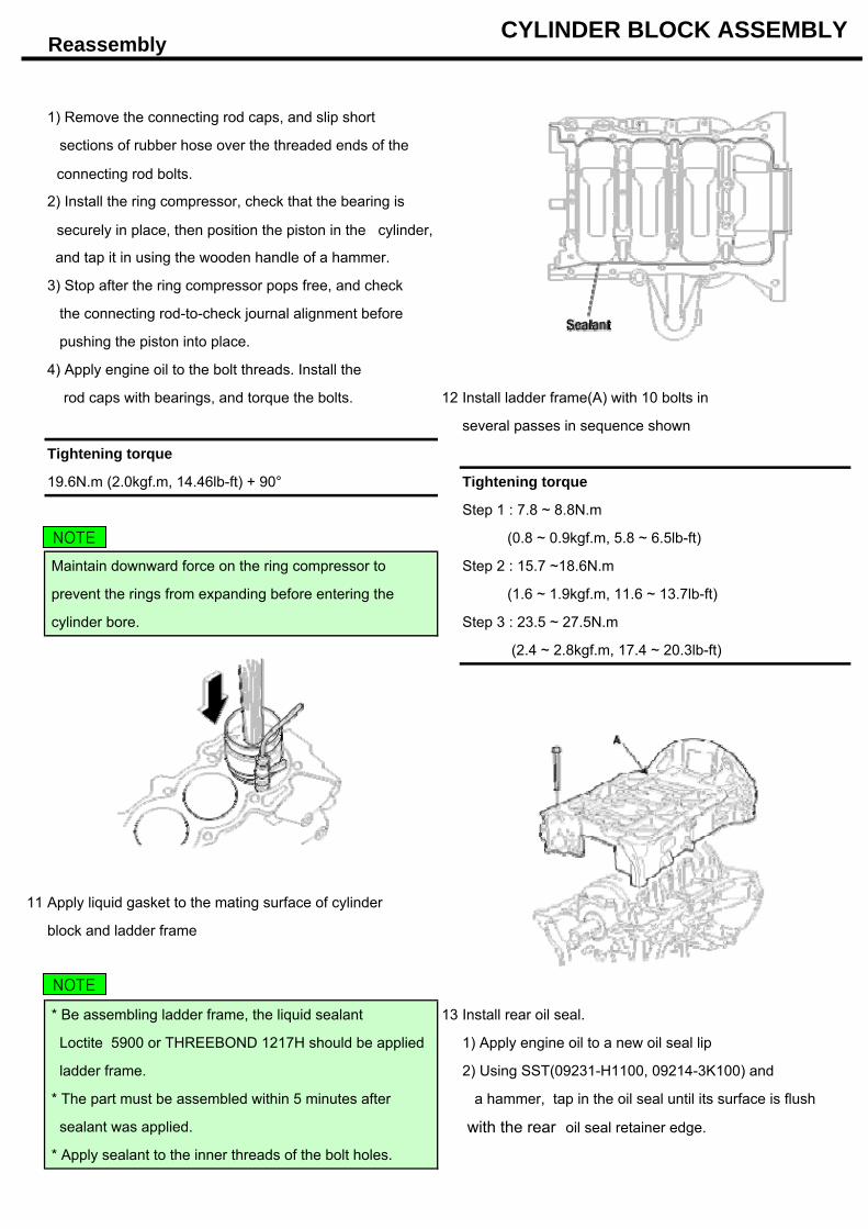
1) Remove the connecting rod caps, and slip short
sections of rubber hose over the threaded ends of the
connecting rod bolts.
2) Install the ring compressor, check that the bearing is
securely in place, then position the piston in the cylinder,
and tap it in using the wooden handle of a hammer.
3) Stop after the ring compressor pops free, and check
the connecting rod-to-check journal alignment before
pushing the piston into place.
4) Apply engine oil to the bolt threads. Install the
rod caps with bearings, and torque the bolts. 12 Install ladder frame(A) with 10 bolts in
several passes in sequence shown
Tightening torque
19.6N.m (2.0kgf.m, 14.46lb-ft) + 90° Tightening torque
Step 1 : 7.8 ~ 8.8N.m
(0.8 ~ 0.9kgf.m, 5.8 ~ 6.5lb-ft)
Maintain downward force on the ring compressor to Step 2 : 15.7 ~18.6N.m
prevent the rings from expanding before entering the (1.6 ~ 1.9kgf.m, 11.6 ~ 13.7lb-ft)
cylinder bore. Step 3 : 23.5 ~ 27.5N.m
(2.4 ~ 2.8kgf.m, 17.4 ~ 20.3lb-ft)
11 Apply liquid gasket to the mating surface of cylinder
block and ladder frame
* Be assembling ladder frame, the liquid sealant 13 Install rear oil seal.
Loctite 5900 or THREEBOND 1217H should be applied 1) Apply engine oil to a new oil seal lip
ladder frame. 2) Using SST(09231-H1100, 09214-3K100) and
* The part must be assembled within 5 minutes after a hammer, tap in the oil seal until its surface is flush
sealant was applied. with the rear oil seal retainer edge.
* Apply sealant to the inner threads of the bolt holes.
NOTE
NOTE
Reassembly CYLINDER BLOCK ASSEMBLY
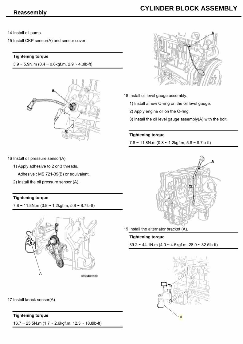
14 Install oil pump.
15 Install CKP sensor(A) and sensor cover.
Tightening torque
3.9 ~ 5.9N.m (0.4 ~ 0.6kgf.m, 2.9 ~ 4.3lb-ft)
18 Install oil level gauge assembly.
1) Install a new O-ring on the oil level gauge.
2) Apply engine oil on the O-ring.
3) Install the oil level gauge assembly(A) with the bolt.
Tightening torque
7.8 ~ 11.8N.m (0.8 ~ 1.2kgf.m, 5.8 ~ 8.7lb-ft)
16 Install oil pressure sensor(A).
1) Apply adhesive to 2 or 3 threads.
Adhesive : MS 721-39(B) or equivalent.
2) Install the oil pressure sensor (A).
Tightening torque
7.8 ~ 11.8N.m (0.8 ~ 1.2kgf.m, 5.8 ~ 8.7lb-ft)
19 Install the alternator bracket (A).
Tightening torque
39.2 ~ 44.1N.m (4.0 ~ 4.5kgf.m, 28.9 ~ 32.5lb-ft)
17 Install knock sensor(A).
Tightening torque
16.7 ~ 25.5N.m (1.7 ~ 2.6kgf.m, 12.3 ~ 18.8lb-ft)
A
A
Reassembly CYLINDER BLOCK ASSEMBLY
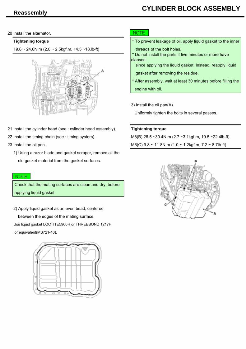
20 Install the alternator.
Tightening torque * To prevent leakage of oil, apply liquid gasket to the inner
19.6 ~ 24.6N.m (2.0 ~ 2.5kgf.m, 14.5 ~18.lb-ft) threads of the bolt holes.* Do not install the parts if five minutes or more haveelapsed since applying the liquid gasket. Instead, reapply liquid
gasket after removing the residue.
* After assembly, wait at least 30 minutes before filling the
engine with oil.
3) Install the oil pan(A).
Uniformly tighten the bolts in several passes.
21 Install the cylinder head (see : cylinder head assembly). Tightening torque
22 Install the timing chain (see : timing system). M8(B):26.5 ~30.4N.m (2.7 ~3.1kgf.m, 19.5 ~22.4lb-ft)
23 Install the oil pan. M6(C):9.8 ~ 11.8N.m (1.0 ~ 1.2kgf.m, 7.2 ~ 8.7lb-ft)
1) Using a razor blade and gasket scraper, remove all the
old gasket material from the gasket surfaces.
Check that the mating surfaces are clean and dry before
applying liquid gasket.
2) Apply liquid gasket as an even bead, centered
between the edges of the mating surface.
Use liquid gasket LOCTITE5900H or THREEBOND 1217H
or equivalent(MS721-40).
NOTE
NOTE
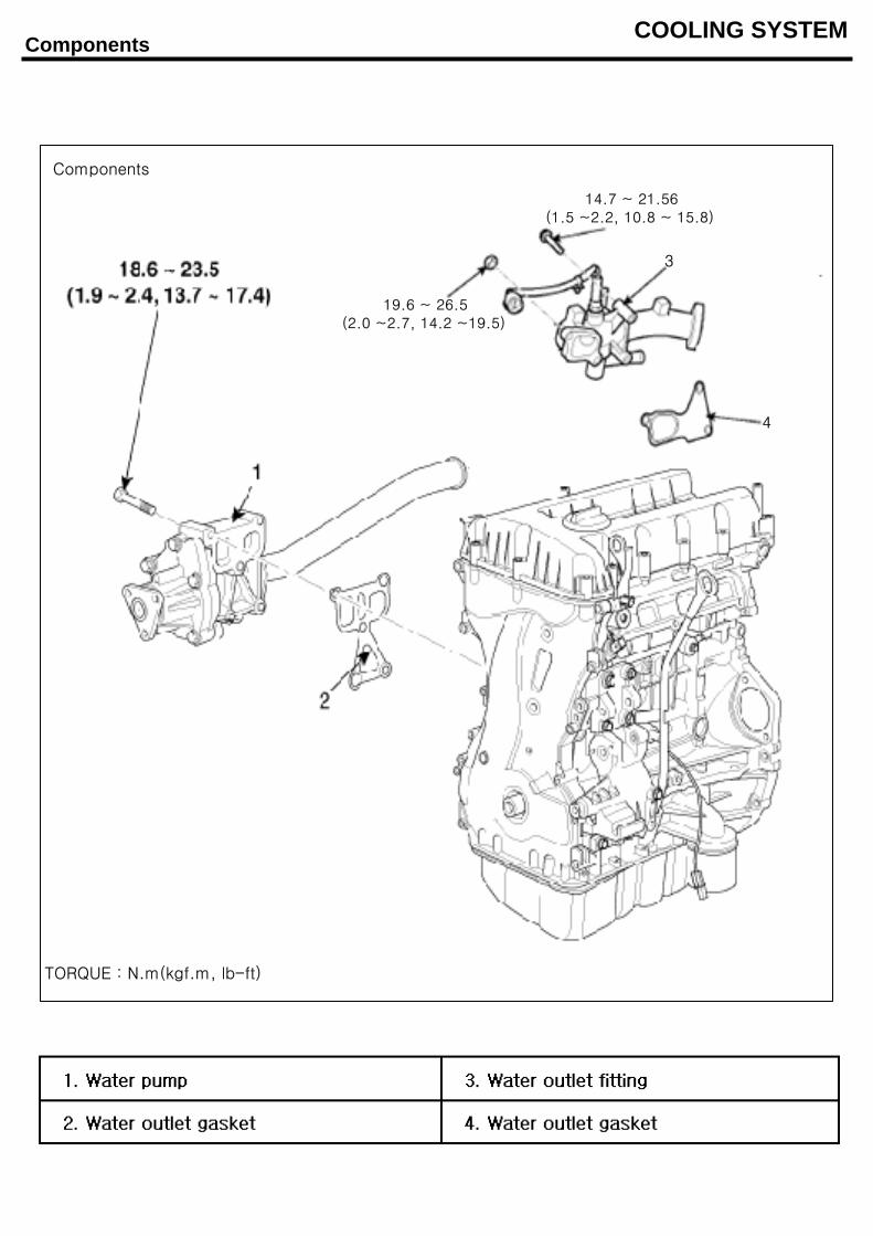
Components COOLING SYSTEM
TORQUE : N.m(kgf.m, lb-ft)
3
4
19.6 ~ 26.5(2.0 ~2.7, 14.2 ~19.5)
14.7 ~ 21.56(1.5 ~2.2, 10.8 ~ 15.8)
Components
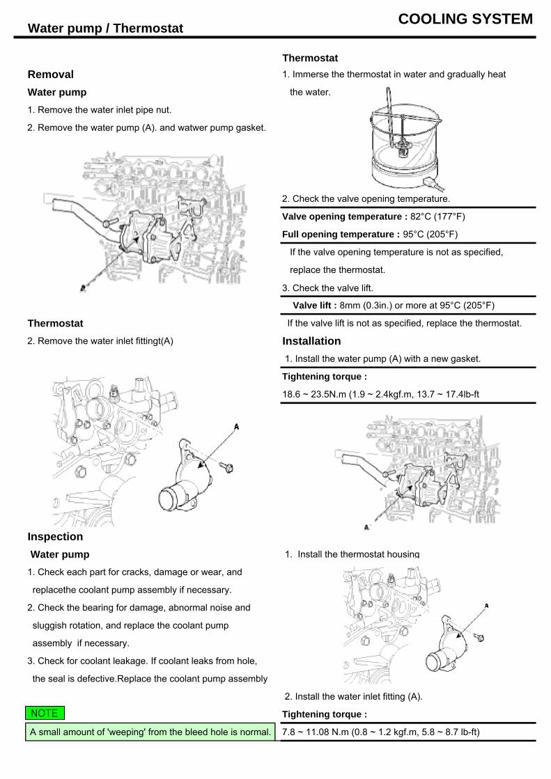
Water pump / Thermostat COOLING SYSTEM
ThermostatRemoval 1. Immerse the thermostat in water and gradually heat
Water pump the water.
1. Remove the water inlet pipe nut.
2. Remove the water pump (A). and watwer pump gasket.
2. Check the valve opening temperature.
Valve opening temperature : 82°C (177°F)
Full opening temperature : 95°C (205°F)
If the valve opening temperature is not as specified,
replace the thermostat.
3. Check the valve lift.
Valve lift : 8mm (0.3in.) or more at 95°C (205°F)
Thermostat If the valve lift is not as specified, replace the thermostat.
2. Remove the water inlet fittingt(A) Installation 1. Install the water pump (A) with a new gasket.
Tightening torque :
18.6 ~ 23.5N.m (1.9 ~ 2.4kgf.m, 13.7 ~ 17.4lb-ft
Thermostat
Inspection Water pump 1. Install the thermostat housing
1. Check each part for cracks, damage or wear, and
replacethe coolant pump assembly if necessary.
2. Check the bearing for damage, abnormal noise and
sluggish rotation, and replace the coolant pump
assembly if necessary.
3. Check for coolant leakage. If coolant leaks from hole,
the seal is defective.Replace the coolant pump assembly
2. Install the water inlet fitting (A).
Tightening torque :
A small amount of 'weeping' from the bleed hole is normal. 7.8 ~ 11.08 N.m (0.8 ~ 1.2 kgf.m, 5.8 ~ 8.7 lb-ft)
NOTE
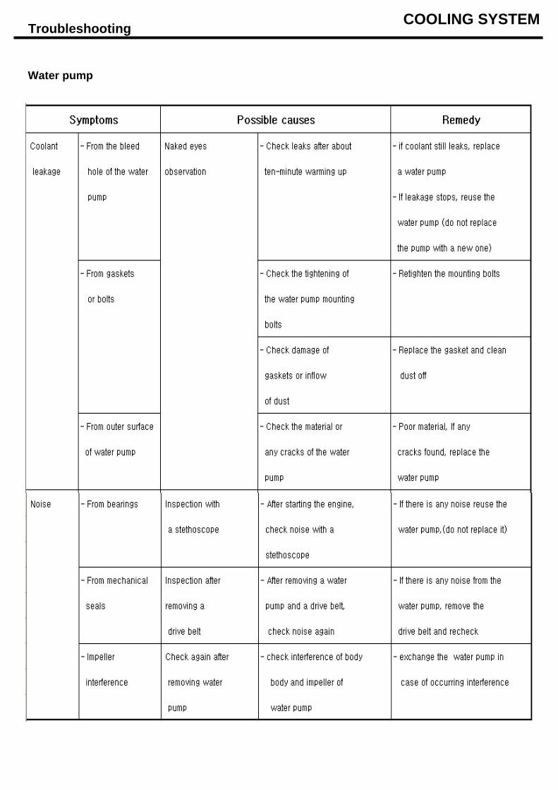
Troubleshooting COOLING SYSTEM
Water pump
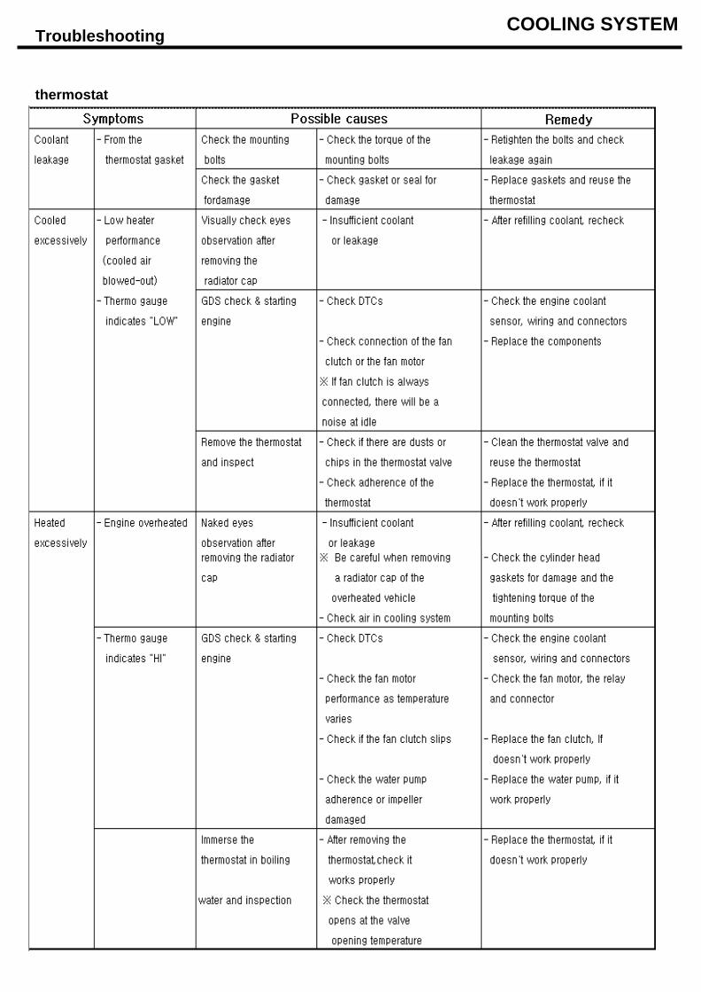
Troubleshooting COOLING SYSTEM
thermostat
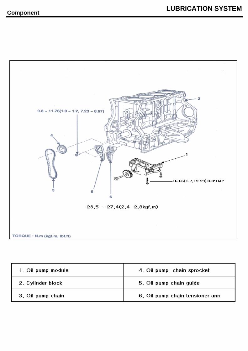
Component LUBRICATION SYSTEM
TORQUE : N.m(kgf.m, lbf,ft)
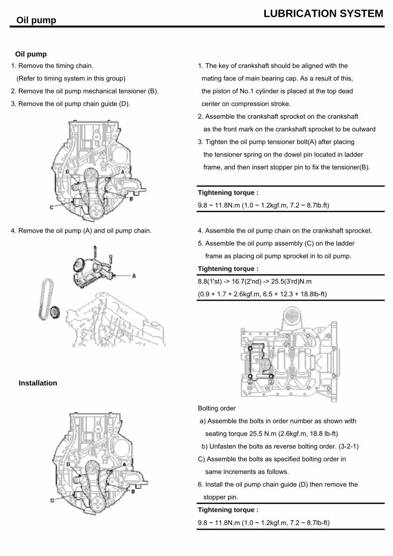
Oil pump LUBRICATION SYSTEM
Oil pump1. Remove the timing chain. 1. The key of crankshaft should be aligned with the
(Refer to timing system in this group) mating face of main bearing cap. As a result of this,
2. Remove the oil pump mechanical tensioner (B). the piston of No.1 cylinder is placed at the top dead
3. Remove the oil pump chain guide (D). center on compression stroke.
2. Assemble the crankshaft sprocket on the crankshaft
as the front mark on the crankshaft sprocket to be outward
3. Tighten the oil pump tensioner bolt(A) after placing
the tensioner spring on the dowel pin located in ladder
frame, and then insert stopper pin to fix the tensioner(B).
Tightening torque :
9.8 ~ 11.8N.m (1.0 ~ 1.2kgf.m, 7.2 ~ 8.7lb.ft)
4. Remove the oil pump (A) and oil pump chain. 4. Assemble the oil pump chain on the crankshaft sprocket.
5. Assemble the oil pump assembly (C) on the ladder
frame as placing oil pump sprocket in to oil pump.
Tightening torque :
8.8(1'st) -> 16.7(2'nd) -> 25.5(3'rd)N.m
(0.9 + 1.7 + 2.6kgf.m, 6.5 + 12.3 + 18.8lb-ft)
Installation
Bolting order
a) Assemble the bolts in order number as shown with
seating torque 25.5 N.m (2.6kgf.m, 18.8 lb-ft)
b) Unfasten the bolts as reverse bolting order. (3-2-1)
C) Assemble the bolts as specified bolting order in
same increments as follows.
6. Install the oil pump chain guide (D) then remove the
stopper pin.
Tightening torque :
9.8 ~ 11.8N.m (1.0 ~ 1.2kgf.m, 7.2 ~ 8.7lb-ft)
Oil pump LUBRICATION SYSTEM
2) Fill with fresh engine oil.
* Prolonged and repeated contact with mineral oil will Capacity :
result in the removal of natural fats from the skin, Total : 5.7 L
leading to dryness, irritation and dermatitis. In Oil pan : 4.8 L
addition, used engine oil contains potentially Drain and refill including oil filter : 5.2L
harmful contaminants which may cause skin cancer
* Exercise caution in order to minimize the length and 3) Install the oil filler cap.
frequency of contact of your skin to used oil. Wear 4. Start engine and check for oil leaks and check the
protective clothing and gloves. Wash your skin oil gauge or light for an indication of oil pressure.
thoroughly with soap and water, or use water-less 5. Recheck the engine oil level.
hand cleaner,to remove any used engine oil. Do not
use gasoline, thinners, or solvents. Inspection
1. Drain the engine oil. 1. Check the engine oil quality.
1) Remove the oil filler cap. Check the oil deterioration, entry of water, discoloring
2) Remove the oil drain plug, and drain the oil of thinning. If the quality is visibly poor, replace the oil.
into a container. 2. Check the engine oil level.
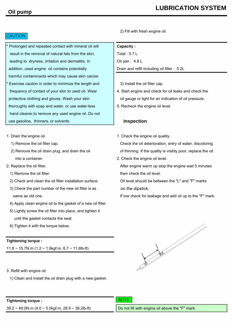
2. Replace the oil filter. After engine warm up stop the engine wait 5 minutes
1) Remove the oil filter. then check the oil level.
2) Check and clean the oil filter installation surface. Oil level should be befween the "L" and "F" marks
3) Check the part number of the new oil filter is as on the dipstick.
same as old one. If low check for leakage and add oil up to the "F" mark.
4) Apply clean engine oil to the gasket of a new oil filter.
5) Lightly screw the oil filter into place, and tighten it
until the gasket contacts the seat.
6) Tighten it with the torque below.
Tightening torque :
11.8 ~ 15.7N.m (1.2 ~ 1.6kgf.m, 8.7 ~ 11.6lb-ft)
3. Refill with engine oil.
1) Clean and install the oil drain plug with a new gasket.
Tightening torque :
39.2 ~ 49.0N.m (4.0 ~ 5.0kgf.m, 28.9 ~ 36.2lb-ft) Do not fill with engine oil above the "F" mark.
CAUTION
NOTE
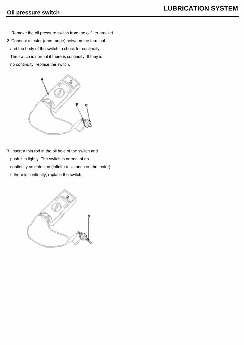
Oil pressure switch LUBRICATION SYSTEM
1. Remove the oil pressure switch from the oilfilter bracket
2. Connect a tester (ohm range) between the terminal
and the body of the switch to check for continuity.
The switch is normal if there is continuity. If they is
no continuity, replace the switch.
3. Insert a thin rod in the oil hole of the switch and
push it in lightly. The switch is normal of no
continuity as detected (infinite resistance on the tester).
If there is continuity, replace the switch.
Eng Oil LUBRICATION SYSTEM
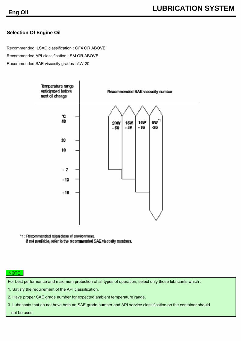
Selection Of Engine Oil
Recommended ILSAC classification : GF4 OR ABOVE
Recommended API classification : SM OR ABOVE
Recommended SAE viscosity grades : 5W-20
For best performance and maximum protection of all types of operation, select only those lubricants which :
1. Satisfy the requirement of the API classification.
2. Have proper SAE grade number for expected ambient temperature range.
3. Lubricants that do not have both an SAE grade number and API service classification on the container should
not be used.
NOTE
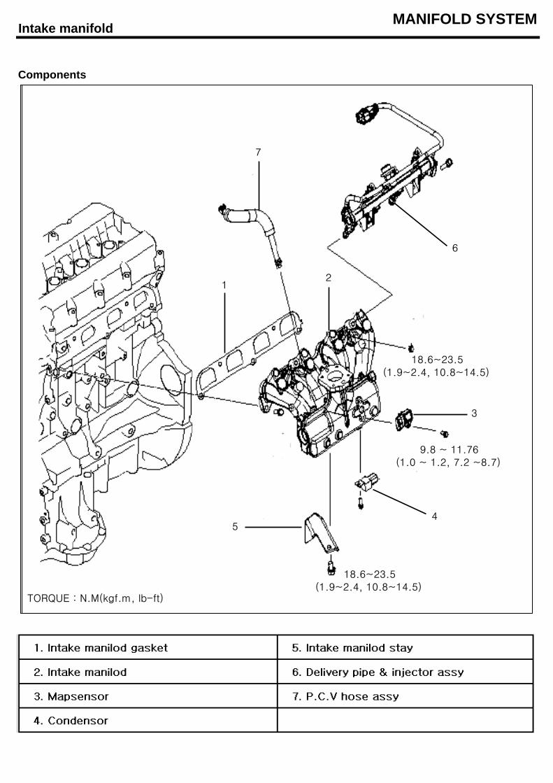
Intake manifold MANIFOLD SYSTEM
Components
18.6~23.5(1.9~2.4, 10.8~14.5)
TORQUE : N.M(kgf.m, lb-ft)
18.6~23.5(1.9~2.4, 10.8~14.5)
9.8 ~ 11.76(1.0 ~ 1.2, 7.2 ~8.7)
12
3
45
6
7
18.6~23.5(1.9~2.4, 10.8~14.5)
TORQUE : N.M(kgf.m, lb-ft)
18.6~23.5(1.9~2.4, 10.8~14.5)
9.8 ~ 11.76(1.0 ~ 1.2, 7.2 ~8.7)
12
3
45
6
7
Intake manifold MANIFOLD SYSTEM
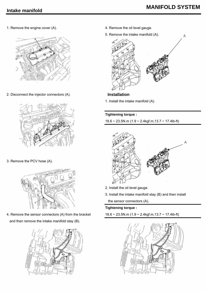
1. Remove the engine cover (A). 4. Remove the oil level gauge.
5. Remove the intake manifold (A).
2. Disconnect the injector connectors (A). Installation1. Install the intake manifold (A).
Tightening torque :
18.6 ~ 23.5N.m (1.9 ~ 2.4kgf.m,13.7 ~ 17.4lb-ft)
3. Remove the PCV hose (A).
2. Install the oil level gauge.
3. Install the intake manifold stay (B) and then install
the sensor connectors (A).
Tightening torque :
4. Remove the sensor connectors (A) from the bracket 18.6 ~ 23.5N.m (1.9 ~ 2.4kgf.m,13.7 ~ 17.4lb-ft)
and then remove the intake manifold stay (B).
A
A
Intake manifold MANIFOLD SYSTEM
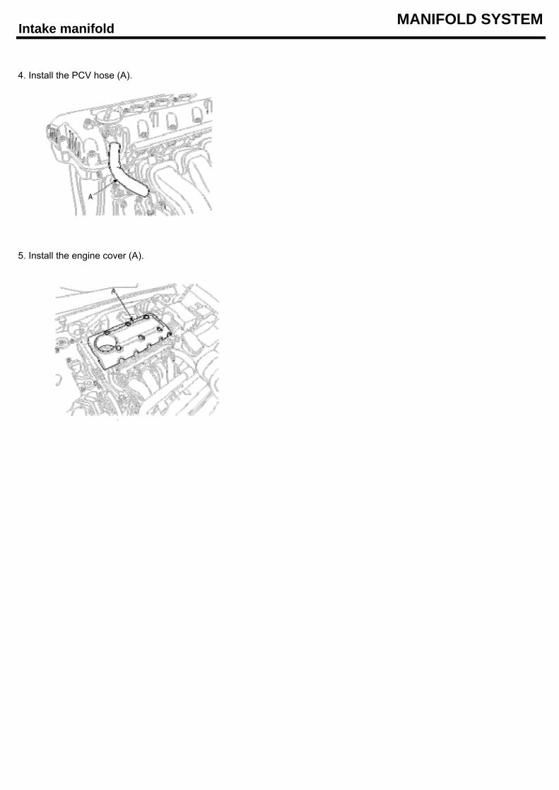
4. Install the PCV hose (A).
5. Install the engine cover (A).
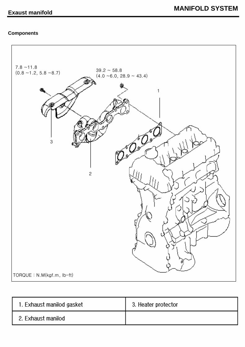
Exaust manifold MANIFOLD SYSTEM
Components
7.8 ~11.8(0.8 ~1.2, 5.8 ~8.7)
39.2 ~ 58.8(4.0 ~6.0, 28.9 ~ 43.4)
TORQUE : N.M(kgf.m, lb-ft)
2
1
3
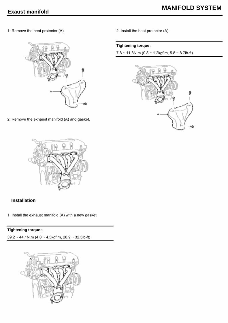
Exaust manifold MANIFOLD SYSTEM
1. Remove the heat protector (A). 2. Install the heat protector (A).
Tightening torque :
7.8 ~ 11.8N.m (0.8 ~ 1.2kgf.m, 5.8 ~ 8.7lb-ft)
2. Remove the exhaust manifold (A) and gasket.
Installation
1. Install the exhaust manifold (A) with a new gasket
Tightening torque :
39.2 ~ 44.1N.m (4.0 ~ 4.5kgf.m, 28.9 ~ 32.5lb-ft)
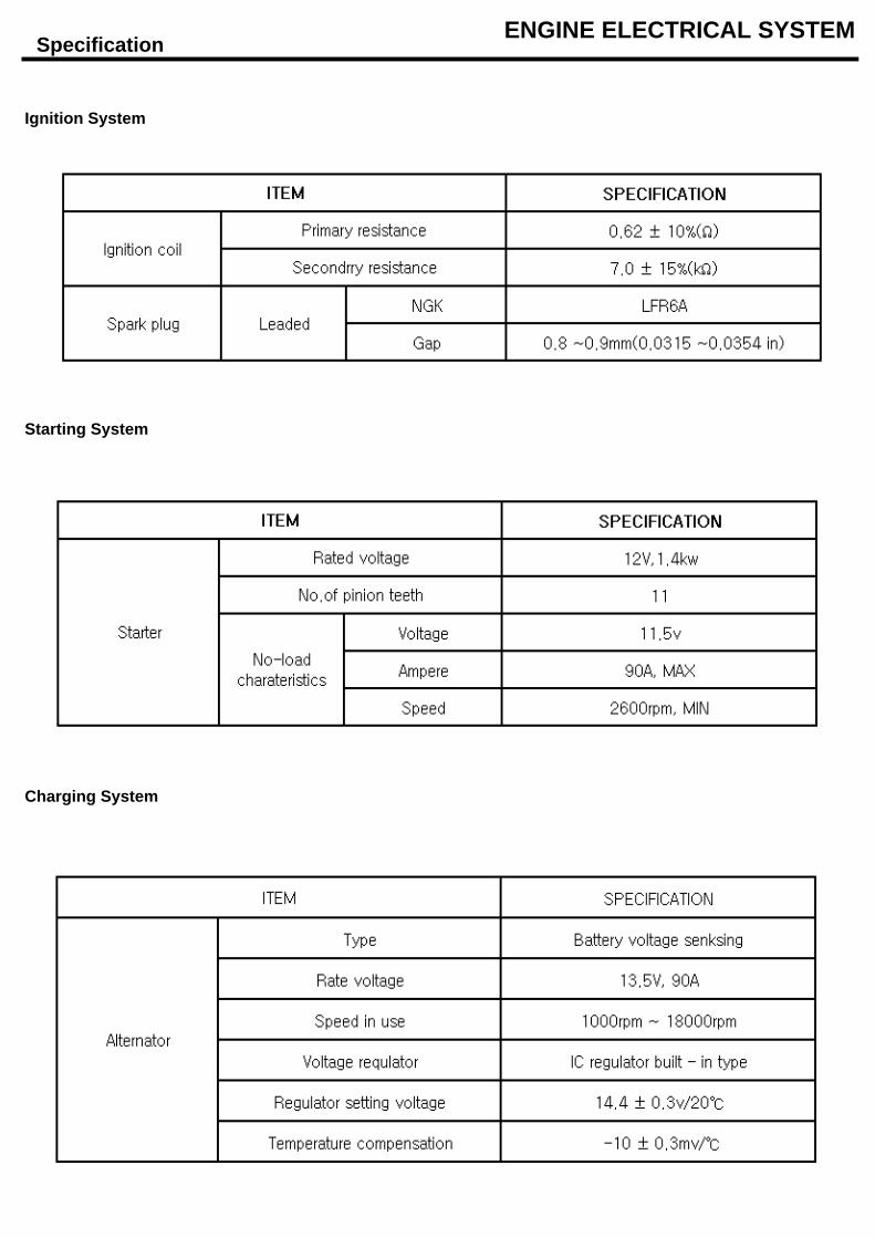
Specification ENGINE ELECTRICAL SYSTEM
Ignition System
Starting System
Charging System
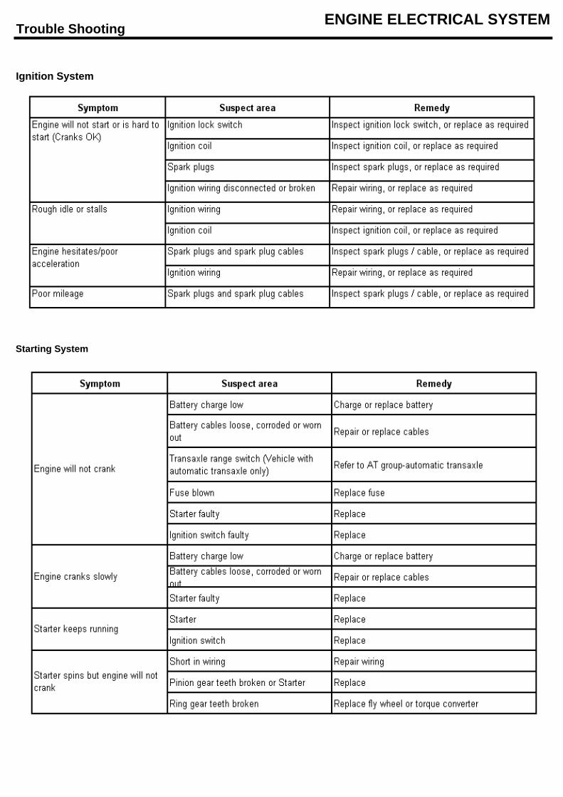
Trouble Shooting ENGINE ELECTRICAL SYSTEM
Ignition System
Starting System
Trouble Shooting ENGINE ELECTRICAL SYSTEM
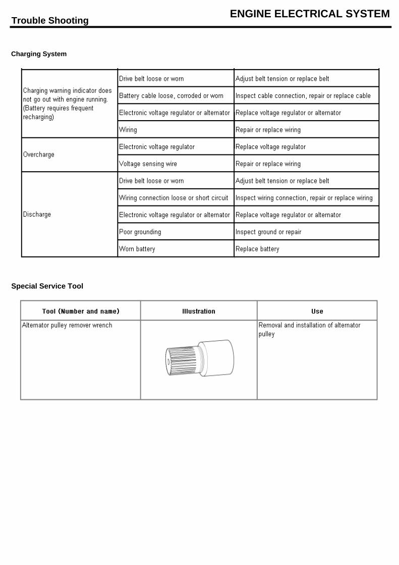
Charging System
Special Service Tool
Ignisionsystem ENGINE ELECTRICAL SYSTEM
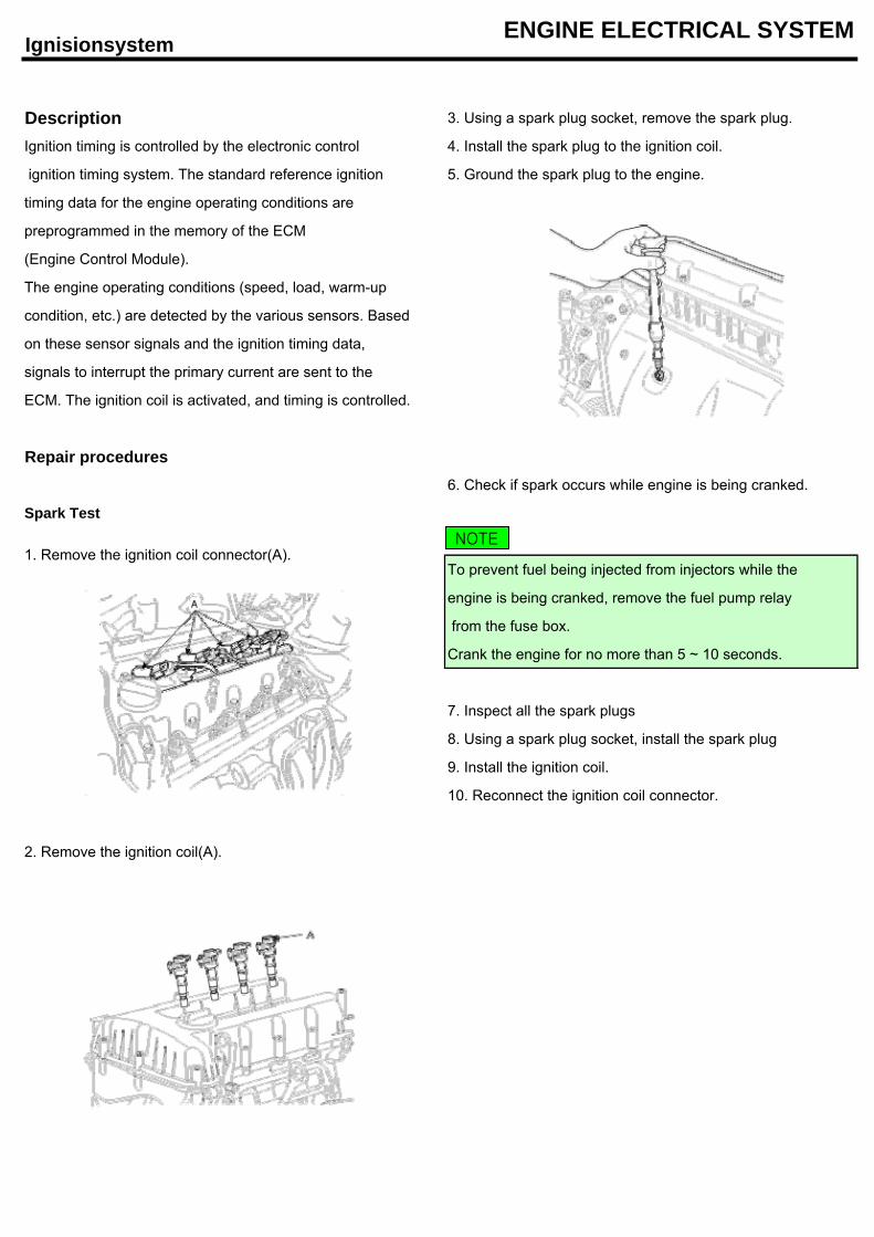
Description 3. Using a spark plug socket, remove the spark plug.
Ignition timing is controlled by the electronic control 4. Install the spark plug to the ignition coil.
ignition timing system. The standard reference ignition 5. Ground the spark plug to the engine.
timing data for the engine operating conditions are
preprogrammed in the memory of the ECM
(Engine Control Module).
The engine operating conditions (speed, load, warm-up
condition, etc.) are detected by the various sensors. Based
on these sensor signals and the ignition timing data,
signals to interrupt the primary current are sent to the
ECM. The ignition coil is activated, and timing is controlled.
Repair procedures6. Check if spark occurs while engine is being cranked.
Spark Test
To prevent fuel being injected from injectors while the
engine is being cranked, remove the fuel pump relay
from the fuse box.
Crank the engine for no more than 5 ~ 10 seconds.
7. Inspect all the spark plugs
8. Using a spark plug socket, install the spark plug
9. Install the ignition coil.
10. Reconnect the ignition coil connector.
2. Remove the ignition coil(A).
1. Remove the ignition coil connector(A).NOTE
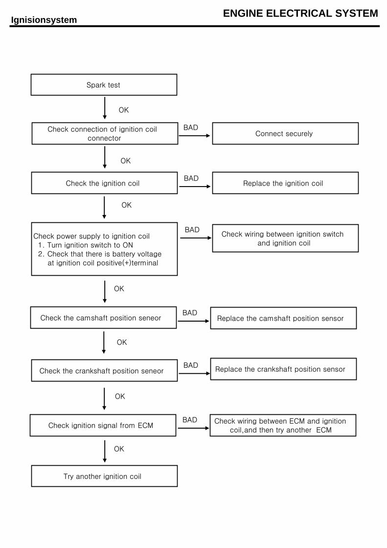
Ignisionsystem ENGINE ELECTRICAL SYSTEM
Spark test
Check connection of ignition coilconnector
Check power supply to ignition coil 1. Turn ignition switch to ON 2. Check that there is battery voltage at ignition coil positive(+)terminal
Check the camshaft position seneor
Replace the crankshaft position sensor
Check ignition signal from ECM
Try another ignition coil
Check the ignition coil
Check the crankshaft position seneor
Connect securely
Replace the ignition coil
Check wiring between ignition switchand ignition coil
Replace the camshaft position sensor
Check wiring between ECM and ignitioncoil,and then try another ECM
OK
OK
OK
OK
OK
OK
OK
BAD
BAD
BAD
BAD
BAD
BAD
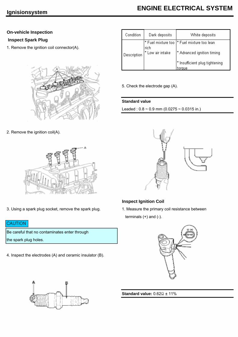
Ignisionsystem ENGINE ELECTRICAL SYSTEM
On-vehicle Inspection
Inspect Spark Plug1. Remove the ignition coil connector(A).
5. Check the electrode gap (A).
Standard value
Leaded : 0.8 ~ 0.9 mm (0.0275 ~ 0.0315 in.)
2. Remove the ignition coil(A).
Inspect Ignition Coil3. Using a spark plug socket, remove the spark plug. 1. Measure the primary coil resistance between
terminals (+) and (-).
Be careful that no contaminates enter through
the spark plug holes.
4. Inspect the electrodes (A) and ceramic insulator (B).
Standard value: 0.62Ω ± 11%
CAUTION
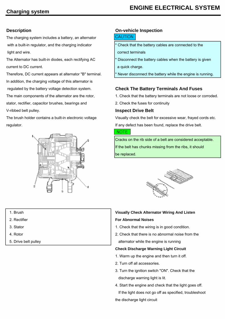
Charging system ENGINE ELECTRICAL SYSTEM
Description On-vehicle InspectionThe charging system includes a battery, an alternator
with a built-in regulator, and the charging indicator * Check that the battery cables are connected to the
light and wire. correct terminals
The Alternator has built-in diodes, each rectifying AC * Disconnect the battery cables when the battery is given
current to DC current. a quick charge.
Therefore, DC current appears at alternator "B" terminal. * Never disconnect the battery while the engine is running.
In addition, the charging voltage of this alternator is
regulated by the battery voltage detection system. Check The Battery Terminals And FusesThe main components of the alternator are the rotor, 1. Check that the battery terminals are not loose or corroded.
stator, rectifier, capacitor brushes, bearings and 2. Check the fuses for continuity
V-ribbed belt pulley. Inspect Drive BeltThe brush holder contains a built-in electronic voltage Visually check the belt for excessive wear, frayed cords etc.
regulator. If any defect has been found, replace the drive belt.
Cracks on the rib side of a belt are considered acceptable.
If the belt has chunks missing from the ribs, it should
be replaced.
1. Brush Visually Check Alternator Wiring And Listen
2. Rectifier For Abnormal Noises
3. Stator 1. Check that the wiring is in good condition.
4. Rotor 2. Check that there is no abnormal noise from the
5. Drive belt pulley alternator while the engine is running
Check Discharge Warning Light Circuit
1. Warm up the engine and then turn it off.
2. Turn off all accessories.
3. Turn the ignition switch "ON". Check that the
discharge warning light is lit.
4. Start the engine and check that the light goes off.
If the light does not go off as specified, troubleshoot
the discharge light circuit
CAUTION
NOTE
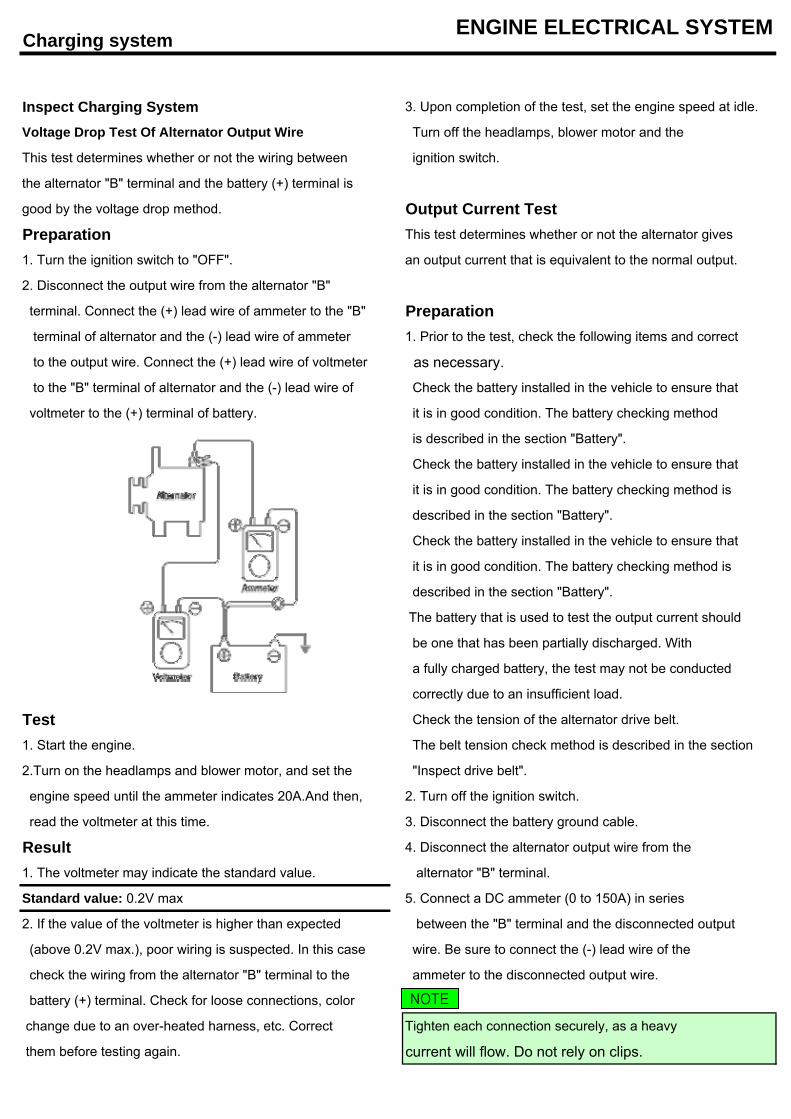
Charging system ENGINE ELECTRICAL SYSTEM
Inspect Charging System 3. Upon completion of the test, set the engine speed at idle.
Voltage Drop Test Of Alternator Output Wire Turn off the headlamps, blower motor and the
This test determines whether or not the wiring between ignition switch.
the alternator "B" terminal and the battery (+) terminal is
good by the voltage drop method. Output Current TestPreparation This test determines whether or not the alternator gives
1. Turn the ignition switch to "OFF". an output current that is equivalent to the normal output.
2. Disconnect the output wire from the alternator "B"
terminal. Connect the (+) lead wire of ammeter to the "B" Preparation terminal of alternator and the (-) lead wire of ammeter 1. Prior to the test, check the following items and correct
to the output wire. Connect the (+) lead wire of voltmeter as necessary.
to the "B" terminal of alternator and the (-) lead wire of Check the battery installed in the vehicle to ensure that
voltmeter to the (+) terminal of battery. it is in good condition. The battery checking method
is described in the section "Battery".
Check the battery installed in the vehicle to ensure that
it is in good condition. The battery checking method is
described in the section "Battery".
Check the battery installed in the vehicle to ensure that
it is in good condition. The battery checking method is
described in the section "Battery".
The battery that is used to test the output current should
be one that has been partially discharged. With
a fully charged battery, the test may not be conducted
correctly due to an insufficient load.
Test Check the tension of the alternator drive belt.
1. Start the engine. The belt tension check method is described in the section
2.Turn on the headlamps and blower motor, and set the "Inspect drive belt".
engine speed until the ammeter indicates 20A.And then, 2. Turn off the ignition switch.
read the voltmeter at this time. 3. Disconnect the battery ground cable.
Result 4. Disconnect the alternator output wire from the
1. The voltmeter may indicate the standard value. alternator "B" terminal.
Standard value: 0.2V max 5. Connect a DC ammeter (0 to 150A) in series
2. If the value of the voltmeter is higher than expected between the "B" terminal and the disconnected output
(above 0.2V max.), poor wiring is suspected. In this case wire. Be sure to connect the (-) lead wire of the
check the wiring from the alternator "B" terminal to the ammeter to the disconnected output wire.
battery (+) terminal. Check for loose connections, color
change due to an over-heated harness, etc. Correct Tighten each connection securely, as a heavy
them before testing again. current will flow. Do not rely on clips.
NOTE
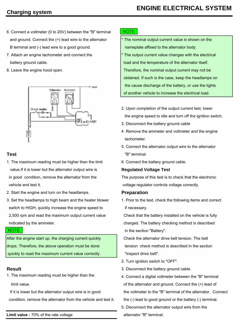
Charging system ENGINE ELECTRICAL SYSTEM
6. Connect a voltmeter (0 to 20V) between the "B" terminal
and ground. Connect the (+) lead wire to the alternator * The nominal output current value is shown on the
B terminal and (-) lead wire to a good ground. nameplate affixed to the alternator body.
7. Attach an engine tachometer and connect the * The output current value changes with the electrical
battery ground cable. load and the temperature of the alternator itself.
8. Leave the engine hood open. Therefore, the nominal output current may not be
obtained. If such is the case, keep the headlamps on
the cause discharge of the battery, or use the lights
of another vehicle to increase the electrical load.
2. Upon completion of the output current test, lower
the engine speed to idle and turn off the ignition switch.
3. Disconnect the battery ground cable
4. Remove the ammeter and voltmeter and the engine
tachometer.
5. Connect the alternator output wire to the alternator
Test "B" terminal.
1. The maximum reading must be higher than the limit 6. Connect the battery ground cable.
value.If it is lower but the alternator output wire is Regulated Voltage Test in good condition, remove the alternator from the The purpose of this test is to check that the electronic
vehicle and test it. voltage regulator controls voltage correctly.
2. Start the engine and turn on the headlamps. Preparation3. Set the headlamps to high beam and the heater blower 1. Prior to the test, check the following items and correct
switch to HIGH, quickly increase the engine speed to if necessary.
2,500 rpm and read the maximum output current value Check that the battery installed on the vehicle is fully
indicated by the ammeter. charged. The battery checking method is described
in the section "Battery".
After the engine start up, the charging current quickly Check the alternator drive belt tension. The belt
drops. Therefore, the above operation must be done tension check method is described in the section
quickly to read the maximum current value correctly. "Inspect drive belt".
2. Turn ignition switch to "OFF".
Result 3. Disconnect the battery ground cable.1. The maximum reading must be higher than the 4. Connect a digital voltmeter between the "B" terminal
limit value. of the alternator and ground. Connect the (+) lead of
If it is lower but the alternator output wire is in good the voltmeter to the "B" terminal of the alternator. Connect
condition, remove the alternator from the vehicle and test it. the (-) lead to good ground or the battery (-) terminal.
5. Disconnect the alternator output wire from the
Limit value : 70% of the rate voltage alternator "B" terminal.
NOTE
NOTE
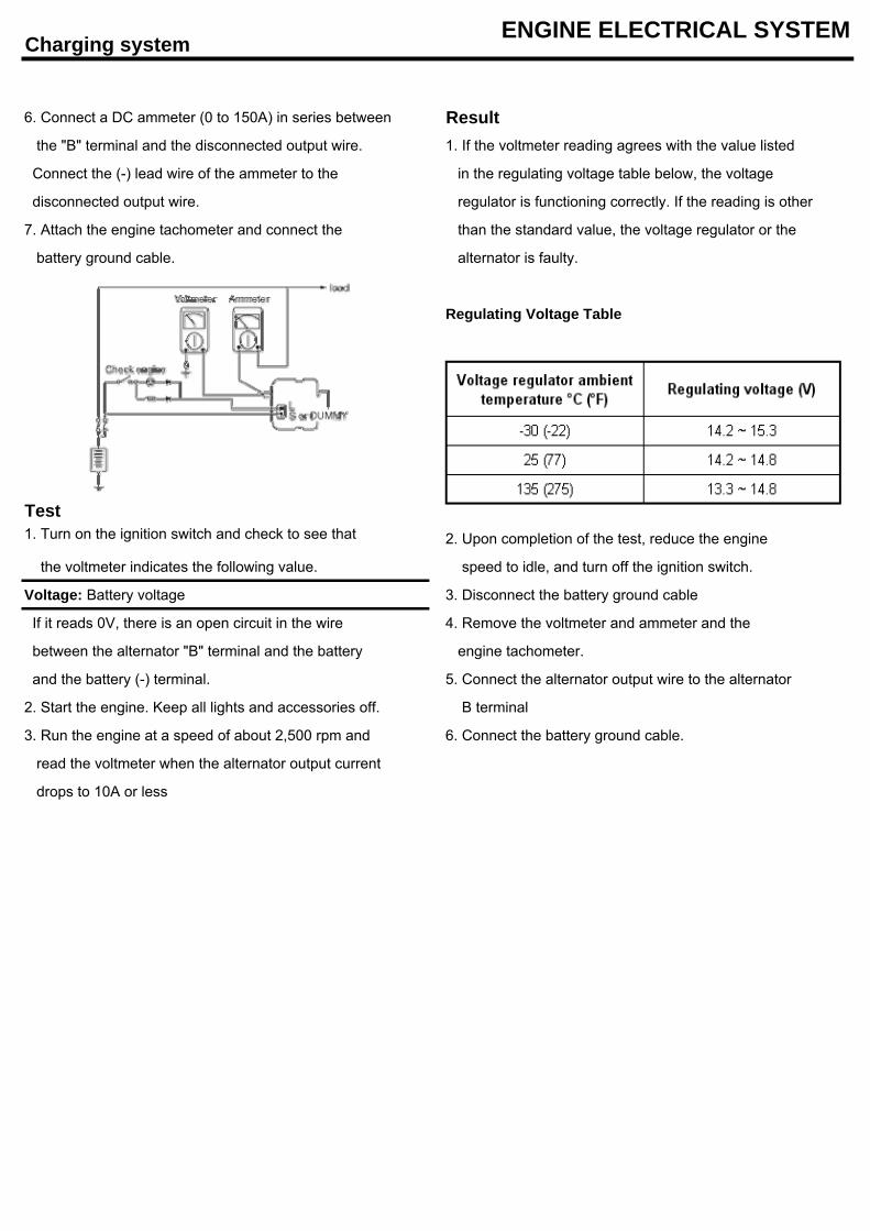
Charging system ENGINE ELECTRICAL SYSTEM
6. Connect a DC ammeter (0 to 150A) in series between Result the "B" terminal and the disconnected output wire. 1. If the voltmeter reading agrees with the value listed
Connect the (-) lead wire of the ammeter to the in the regulating voltage table below, the voltage
disconnected output wire. regulator is functioning correctly. If the reading is other
7. Attach the engine tachometer and connect the than the standard value, the voltage regulator or the
battery ground cable. alternator is faulty.
Regulating Voltage Table
Test1. Turn on the ignition switch and check to see that 2. Upon completion of the test, reduce the engine
the voltmeter indicates the following value. speed to idle, and turn off the ignition switch.
Voltage: Battery voltage 3. Disconnect the battery ground cable
If it reads 0V, there is an open circuit in the wire 4. Remove the voltmeter and ammeter and the
between the alternator "B" terminal and the battery engine tachometer.
and the battery (-) terminal. 5. Connect the alternator output wire to the alternator
2. Start the engine. Keep all lights and accessories off. B terminal
3. Run the engine at a speed of about 2,500 rpm and 6. Connect the battery ground cable.
read the voltmeter when the alternator output current
drops to 10A or less
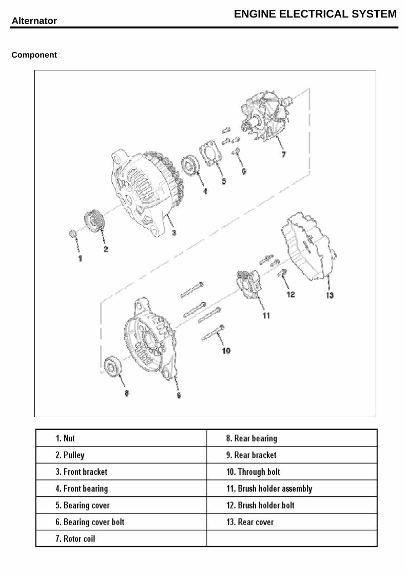
Alternator ENGINE ELECTRICAL SYSTEM
Component
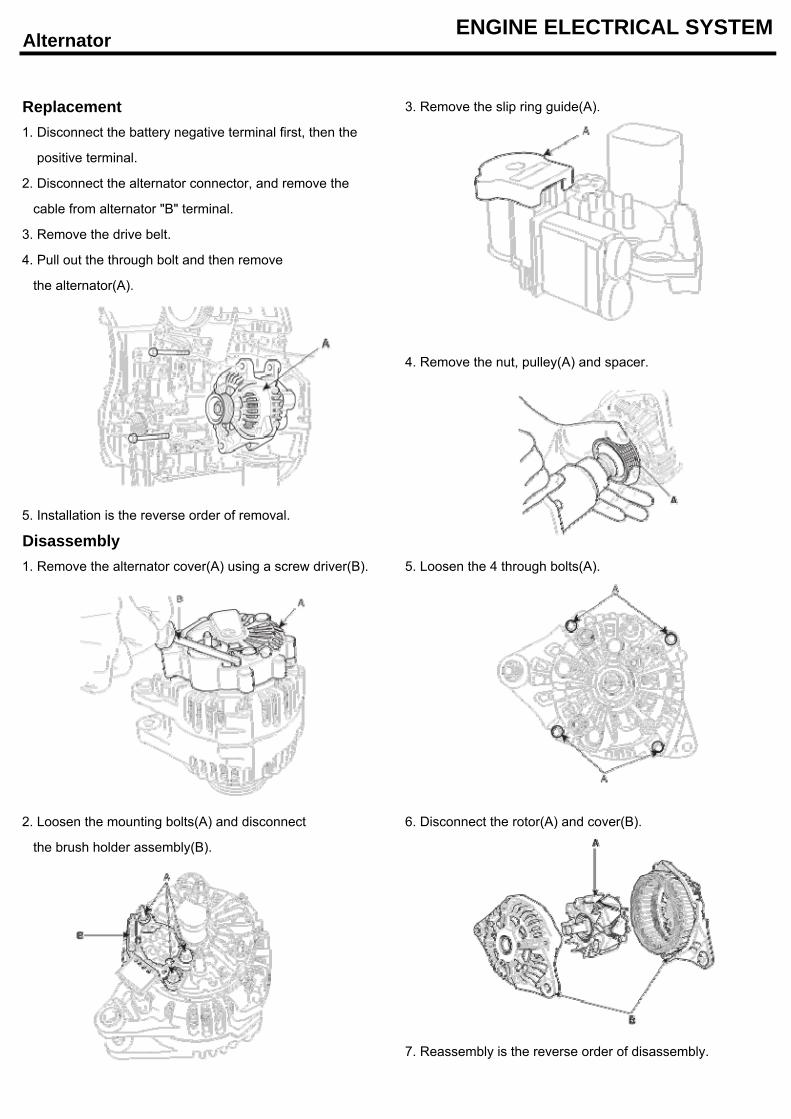
Alternator ENGINE ELECTRICAL SYSTEM
Replacement 3. Remove the slip ring guide(A).
1. Disconnect the battery negative terminal first, then the
positive terminal.
2. Disconnect the alternator connector, and remove the
cable from alternator "B" terminal.
3. Remove the drive belt.
4. Pull out the through bolt and then remove
the alternator(A).
4. Remove the nut, pulley(A) and spacer.
5. Installation is the reverse order of removal.
Disassembly1. Remove the alternator cover(A) using a screw driver(B). 5. Loosen the 4 through bolts(A).
2. Loosen the mounting bolts(A) and disconnect 6. Disconnect the rotor(A) and cover(B).
the brush holder assembly(B).
7. Reassembly is the reverse order of disassembly.
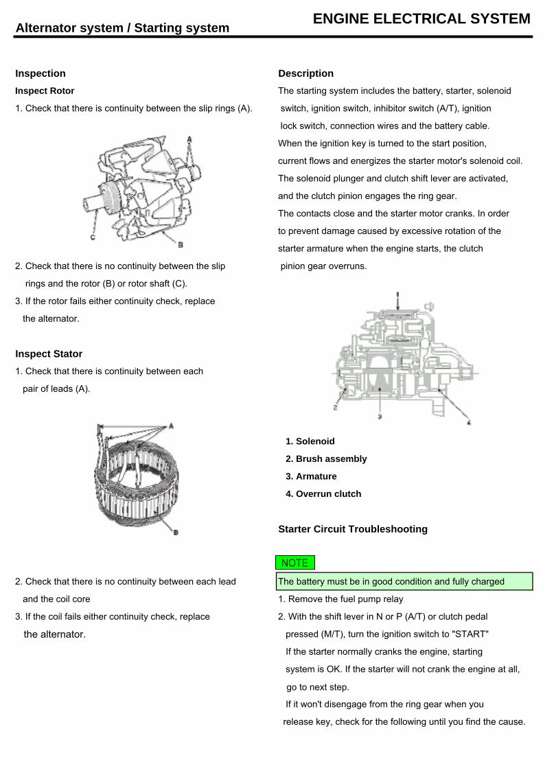
Alternator system / Starting system ENGINE ELECTRICAL SYSTEM
Inspection DescriptionInspect Rotor The starting system includes the battery, starter, solenoid
1. Check that there is continuity between the slip rings (A). switch, ignition switch, inhibitor switch (A/T), ignition
lock switch, connection wires and the battery cable.
When the ignition key is turned to the start position,
current flows and energizes the starter motor's solenoid coil.
The solenoid plunger and clutch shift lever are activated,
and the clutch pinion engages the ring gear.
The contacts close and the starter motor cranks. In order
to prevent damage caused by excessive rotation of the
starter armature when the engine starts, the clutch
2. Check that there is no continuity between the slip pinion gear overruns.
rings and the rotor (B) or rotor shaft (C).
3. If the rotor fails either continuity check, replace
the alternator.
Inspect Stator1. Check that there is continuity between each
pair of leads (A).
1. Solenoid
2. Brush assembly
3. Armature
4. Overrun clutch
Starter Circuit Troubleshooting
2. Check that there is no continuity between each lead The battery must be in good condition and fully charged
and the coil core 1. Remove the fuel pump relay
3. If the coil fails either continuity check, replace 2. With the shift lever in N or P (A/T) or clutch pedal
the alternator. pressed (M/T), turn the ignition switch to "START"
If the starter normally cranks the engine, starting
system is OK. If the starter will not crank the engine at all,
go to next step.
If it won't disengage from the ring gear when you
release key, check for the following until you find the cause.
NOTE
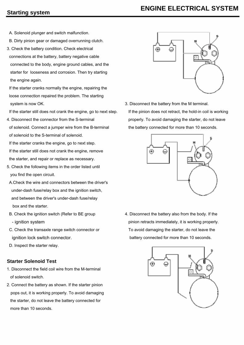
Starting system ENGINE ELECTRICAL SYSTEM
A. Solenoid plunger and switch malfunction.
B. Dirty pinion gear or damaged overrunning clutch.
3. Check the battery condition. Check electrical
connections at the battery, battery negative cable
connected to the body, engine ground cables, and the
starter for looseness and corrosion. Then try starting
the engine again.
If the starter cranks normally the engine, repairing the
loose connection repaired the problem. The starting
system is now OK. 3. Disconnect the battery from the M terminal.
If the starter still does not crank the engine, go to next step. If the pinion does not retract, the hold-in coil is working
4. Disconnect the connector from the S-terminal properly. To avoid damaging the starter, do not leave
of solenoid. Connect a jumper wire from the B-terminal the battery connected for more than 10 seconds.
of solenoid to the S-terminal of solenoid.
If the starter cranks the engine, go to next step.
If the starter still does not crank the engine, remove
the starter, and repair or replace as necessary.
5. Check the following items in the order listed until
you find the open circuit.
A.Check the wire and connectors between the driver's
under-dash fuse/relay box and the ignition switch,
and between the driver's under-dash fuse/relay
box and the starter.
B. Check the ignition switch (Refer to BE group 4. Disconnect the battery also from the body. If the
- ignition system pinion retracts immediately, it is working properly.
C. Check the transaxle range switch connector or To avoid damaging the starter, do not leave the
ignition lock switch connector. battery connected for more than 10 seconds.
D. Inspect the starter relay.
Starter Solenoid Test1. Disconnect the field coil wire from the M-terminal
of solenoid switch.
2. Connect the battery as shown. If the starter pinion
pops out, it is working properly. To avoid damaging
the starter, do not leave the battery connected for
more than 10 seconds.
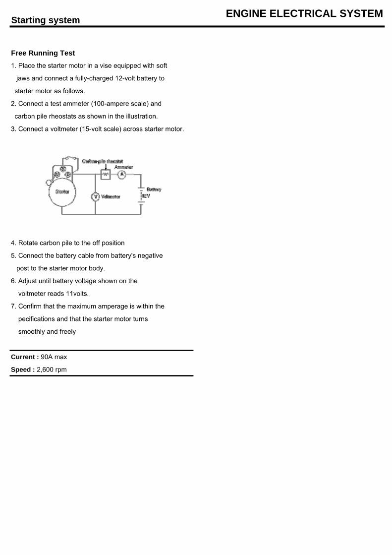
Starting system ENGINE ELECTRICAL SYSTEM
Free Running Test1. Place the starter motor in a vise equipped with soft
jaws and connect a fully-charged 12-volt battery to
starter motor as follows.
2. Connect a test ammeter (100-ampere scale) and
carbon pile rheostats as shown in the illustration.
3. Connect a voltmeter (15-volt scale) across starter motor.
4. Rotate carbon pile to the off position
5. Connect the battery cable from battery's negative
post to the starter motor body.
6. Adjust until battery voltage shown on the
voltmeter reads 11volts.
7. Confirm that the maximum amperage is within the
pecifications and that the starter motor turns
smoothly and freely
Current : 90A max
Speed : 2,600 rpm
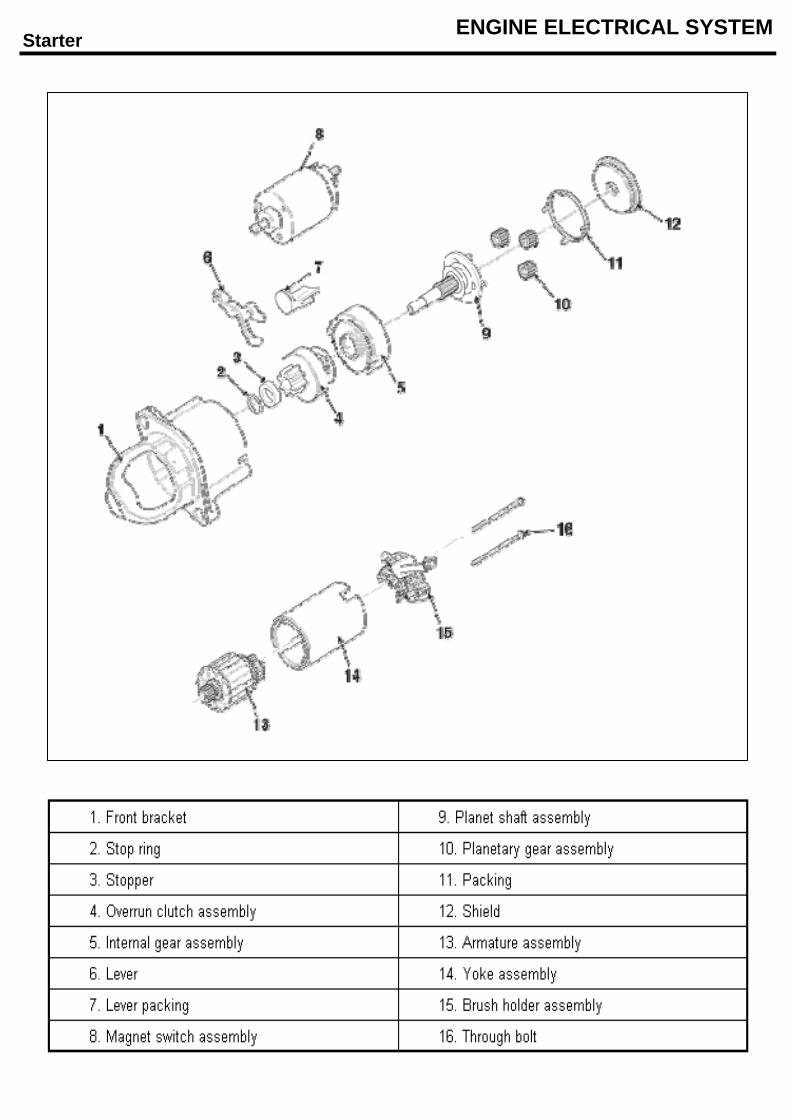
Starter ENGINE ELECTRICAL SYSTEM
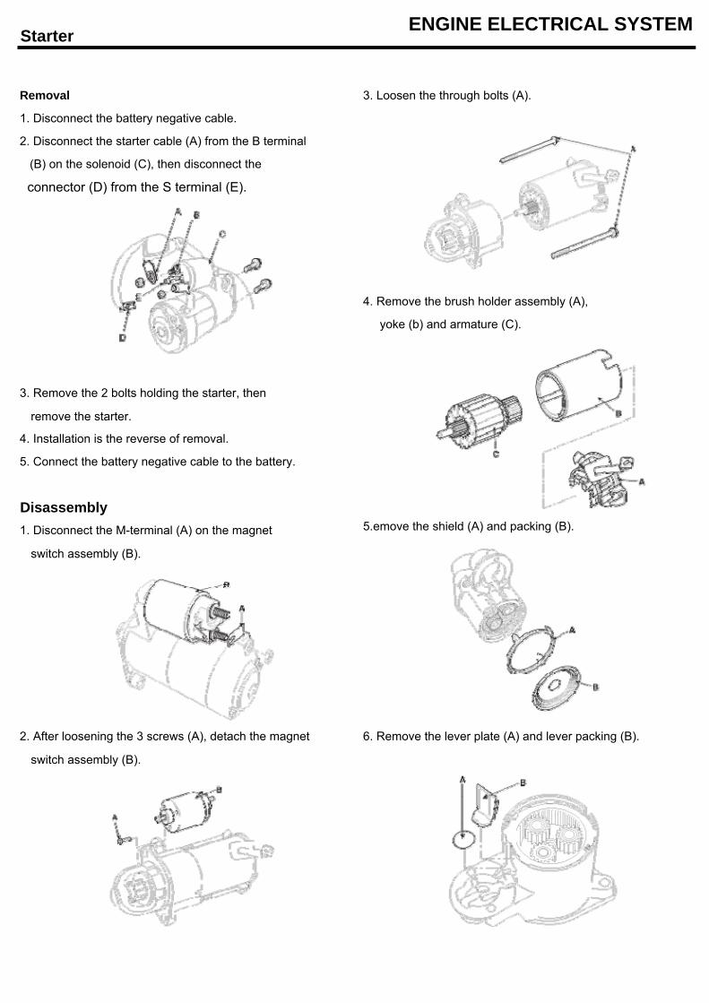
Starter ENGINE ELECTRICAL SYSTEM
Removal 3. Loosen the through bolts (A).
1. Disconnect the battery negative cable.
2. Disconnect the starter cable (A) from the B terminal
(B) on the solenoid (C), then disconnect the
connector (D) from the S terminal (E).
4. Remove the brush holder assembly (A),
yoke (b) and armature (C).
3. Remove the 2 bolts holding the starter, then
remove the starter.
4. Installation is the reverse of removal.
5. Connect the battery negative cable to the battery.
Disassembly1. Disconnect the M-terminal (A) on the magnet 5.emove the shield (A) and packing (B).
switch assembly (B).
2. After loosening the 3 screws (A), detach the magnet 6. Remove the lever plate (A) and lever packing (B).
switch assembly (B).
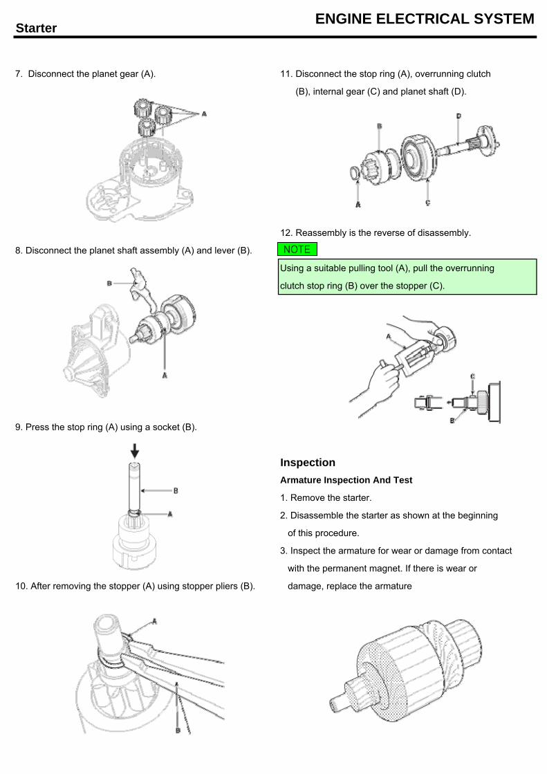
Starter ENGINE ELECTRICAL SYSTEM
7. Disconnect the planet gear (A). 11. Disconnect the stop ring (A), overrunning clutch
(B), internal gear (C) and planet shaft (D).
12. Reassembly is the reverse of disassembly.
8. Disconnect the planet shaft assembly (A) and lever (B).
Using a suitable pulling tool (A), pull the overrunning
clutch stop ring (B) over the stopper (C).
9. Press the stop ring (A) using a socket (B).
InspectionArmature Inspection And Test
1. Remove the starter.
2. Disassemble the starter as shown at the beginning
of this procedure.
3. Inspect the armature for wear or damage from contact
with the permanent magnet. If there is wear or
10. After removing the stopper (A) using stopper pliers (B). damage, replace the armature
NOTE
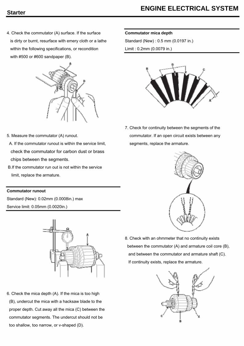
Starter ENGINE ELECTRICAL SYSTEM
4. Check the commutator (A) surface. If the surface Commutator mica depth
is dirty or burnt, resurface with emery cloth or a lathe Standard (New) : 0.5 mm (0.0197 in.)
within the following specifications, or recondition Limit : 0.2mm (0.0079 in.)
with #500 or #600 sandpaper (B).
7. Check for continuity between the segments of the
5. Measure the commutator (A) runout. commutator. If an open circuit exists between any
A. If the commutator runout is within the service limit, segments, replace the armature.
check the commutator for carbon dust or brass
chips between the segments.
B.If the commutator run out is not within the service
limit, replace the armature.
Commutator runout
Standard (New): 0.02mm (0.0008in.) max
Service limit: 0.05mm (0.0020in.)
8. Check with an ohmmeter that no continuity exists
between the commutator (A) and armature coil core (B),
and between the commutator and armature shaft (C).
If continuity exists, replace the armature.
6. Check the mica depth (A). If the mica is too high
(B), undercut the mica with a hacksaw blade to the
proper depth. Cut away all the mica (C) between the
commutator segments. The undercut should not be
too shallow, too narrow, or v-shaped (D).
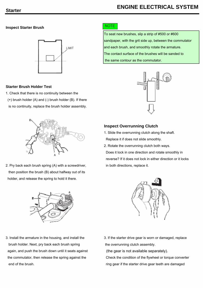
Starter ENGINE ELECTRICAL SYSTEM
Inspect Starter BrushTo seat new brushes, slip a strip of #500 or #600
sandpaper, with the grit side up, between the commutator
and each brush, and smoothly rotate the armature.
The contact surface of the brushes will be sanded to
the same contour as the commutator.
Starter Brush Holder Test1. Check that there is no continuity between the
(+) brush holder (A) and (-) brush holder (B). If there
is no continuity, replace the brush holder assembly.
Inspect Overrunning Clutch1. Slide the overrunning clutch along the shaft.
Replace it if does not slide smoothly.
2. Rotate the overrunning clutch both ways.
Does it lock in one direction and rotate smoothly in
reverse? If it does not lock in either direction or it locks
2. Pry back each brush spring (A) with a screwdriver, in both directions, replace it.
then position the brush (B) about halfway out of its
holder, and release the spring to hold it there.
3. Install the armature in the housing, and install the 3. If the starter drive gear is worn or damaged, replace
brush holder. Next, pry back each brush spring the overrunning clutch assembly.
again, and push the brush down until it seats against (the gear is not available separately).
the commutator, then release the spring against the Check the condition of the flywheel or torque converter
end of the brush. ring gear if the starter drive gear teeth are damaged
LIMIT
NOTE
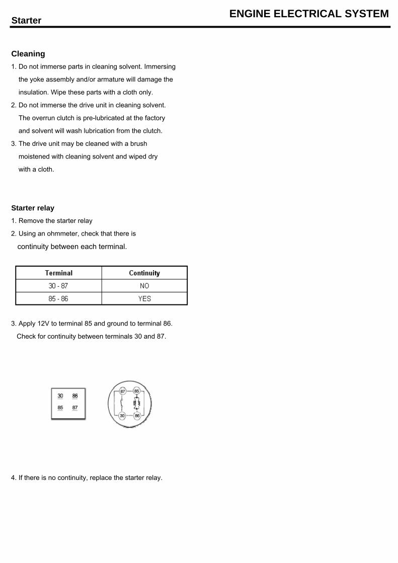
Starter ENGINE ELECTRICAL SYSTEM
Cleaning1. Do not immerse parts in cleaning solvent. Immersing
the yoke assembly and/or armature will damage the
insulation. Wipe these parts with a cloth only.
2. Do not immerse the drive unit in cleaning solvent.
The overrun clutch is pre-lubricated at the factory
and solvent will wash lubrication from the clutch.
3. The drive unit may be cleaned with a brush
moistened with cleaning solvent and wiped dry
with a cloth.
Starter relay1. Remove the starter relay
2. Using an ohmmeter, check that there is
continuity between each terminal.
3. Apply 12V to terminal 85 and ground to terminal 86.
Check for continuity between terminals 30 and 87.
4. If there is no continuity, replace the starter relay.
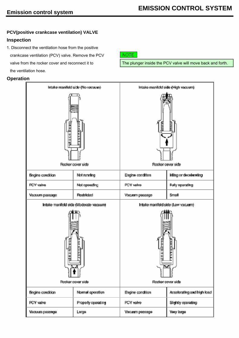
Emission control system EMISSION CONTROL SYSTEM
PCV(positive crankcase ventilation) VALVE
Inspection1. Disconnect the ventilation hose from the positive
crankcase ventilation (PCV) valve. Remove the PCV
valve from the rocker cover and reconnect it to The plunger inside the PCV valve will move back and forth.
the ventilation hose.
Operation
NOTE
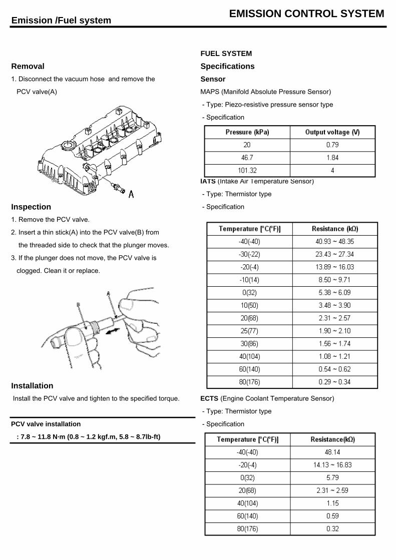
Emission /Fuel system EMISSION CONTROL SYSTEM
FUEL SYSTEM
Removal Specifications1. Disconnect the vacuum hose and remove the Sensor PCV valve(A) MAPS (Manifold Absolute Pressure Sensor)
- Type: Piezo-resistive pressure sensor type
- Specification
IATS (Intake Air Temperature Sensor)
- Type: Thermistor type
Inspection - Specification
1. Remove the PCV valve.
2. Insert a thin stick(A) into the PCV valve(B) from
the threaded side to check that the plunger moves.
3. If the plunger does not move, the PCV valve is
clogged. Clean it or replace.
Installation Install the PCV valve and tighten to the specified torque. ECTS (Engine Coolant Temperature Sensor)
- Type: Thermistor type
PCV valve installation - Specification
: 7.8 ~ 11.8 N·m (0.8 ~ 1.2 kgf.m, 5.8 ~ 8.7lb-ft)
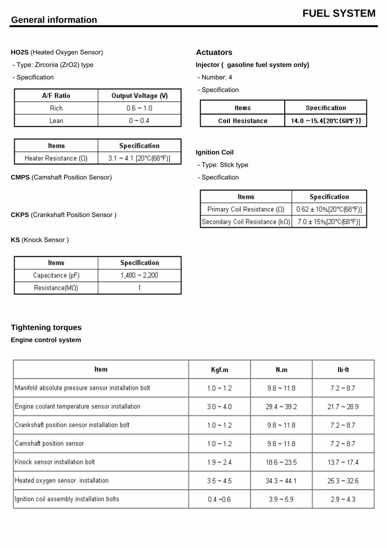
General information FUEL SYSTEM
HO2S (Heated Oxygen Sensor) Actuators - Type: Zirconia (ZrO2) type Injector ( gasoline fuel system only)
- Specification - Number: 4
- Specification
Ignition Coil
- Type: Stick type
CMPS (Camshaft Position Sensor) - Specification
CKPS (Crankshaft Position Sensor )
KS (Knock Sensor )
Tightening torquesEngine control system
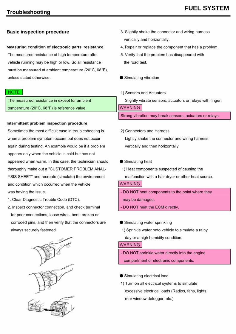
Troubleshooting FUEL SYSTEM
Basic inspection procedure 3. Slightly shake the connector and wiring harness
vertically and horizontally.
Measuring condition of electronic parts' resistance 4. Repair or replace the component that has a problem.
The measured resistance at high temperature after 5. Verify that the problem has disappeared with
vehicle running may be high or low. So all resistance the road test.
must be measured at ambient temperature (20°C, 68°F),
unless stated otherwise. Simulating vibration
1) Sensors and Actuators
The measured resistance in except for ambient Slightly vibrate sensors, actuators or relays with finger.
temperature (20°C, 68°F) is reference value.
Strong vibration may break sensors, actuators or relays
Intermittent problem inspection procedure
Sometimes the most difficult case in troubleshooting is 2) Connectors and Harness
when a problem symptom occurs but does not occur Lightly shake the connector and wiring harness
again during testing. An example would be if a problem vertically and then horizontally
appears only when the vehicle is cold but has not
appeared when warm. In this case, the technician should Simulating heat
thoroughly make out a "CUSTOMER PROBLEM ANAL- 1) Heat components suspected of causing the
YSIS SHEET" and recreate (simulate) the environment malfunction with a hair dryer or other heat source.
and condition which occurred when the vehicle
was having the issue. - DO NOT heat components to the point where they
1. Clear Diagnostic Trouble Code (DTC). may be damaged.
2. Inspect connector connection, and check terminal - DO NOT heat the ECM directly.
for poor connections, loose wires, bent, broken or
corroded pins, and then verify that the connectors are Simulating water sprinkling
always securely fastened. 1) Sprinkle water onto vehicle to simulate a rainy
day or a high humidity condition.
- DO NOT sprinkle water directly into the engine
compartment or electronic components.
Simulating electrical load
1) Turn on all electrical systems to simulate
excessive electrical loads (Radios, fans, lights,
rear window defogger, etc.).
NOTE
WARNING
WARNING
WARNING
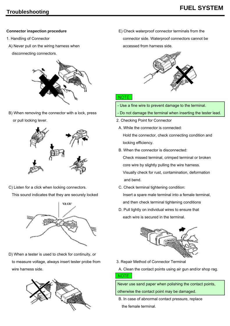
Troubleshooting FUEL SYSTEM
Connector inspection procedure E) Check waterproof connector terminals from the
1. Handling of Connector connector side. Waterproof connectors cannot be
A) Never pull on the wiring harness when accessed from harness side.
disconnecting connectors.
- Use a fine wire to prevent damage to the terminal.
B) When removing the connector with a lock, press - Do not damage the terminal when inserting the tester lead.
or pull locking lever. 2. Checking Point for Connector
A. While the connector is connected:
Hold the connector, check connecting condition and
locking efficiency.
B. When the connector is disconnected:
Check missed terminal, crimped terminal or broken
core wire by slightly pulling the wire harness.
Visually check for rust, contamination, deformation
and bend.
C) Listen for a click when locking connectors. C. Check terminal tightening condition:
This sound indicates that they are securely locked Insert a spare male terminal into a female terminal,
and then check terminal tightening conditions
D. Pull lightly on individual wires to ensure that
each wire is secured in the terminal.
D) When a tester is used to check for continuity, or
to measure voltage, always insert tester probe from 3. Repair Method of Connector Terminal
wire harness side. A. Clean the contact points using air gun and/or shop rag.
Never use sand paper when polishing the contact points,
otherwise the contact point may be damaged.
B. In case of abnormal contact pressure, replace
the female terminal.
NOTE
NOTE
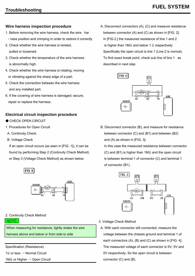
Troubleshooting FUEL SYSTEM
Wire harness inspection procedure A. Disconnect connectors (A), (C) and measure resistance
1. Before removing the wire harness, check the wire har between connector (A) and (C) as shown in [FIG. 2].
- ness position and crimping in order to restore it correctly In [FIG.2.] the measured resistance of line 1 and 2
2. Check whether the wire harness is twisted, is higher than 1MΩ and below 1 Ω respectively
pulled or loosened. Specifically the open circuit is line 1 (Line 2 is normal).
3. Check whether the temperature of the wire harness To find exact break point, check sub line of line 1 as
is abnormally high. described in next step
4. Check whether the wire harness is rotating, moving
or vibrating against the sharp edge of a part.
5. Check the connection between the wire harness
and any installed part.
6. If the covering of wire harness is damaged; secure,
repair or replace the harness.
Electrical circuit inspection procedure CHECK OPEN CIRCUIT
1. Procedures for Open Circuit B. Disconnect connector (B), and measure for resistance
A. Continuity Check between connector (C) and (B1) and between (B2)
B. Voltage Check and (A) as shown in [FIG. 3].
If an open circuit occurs (as seen in [FIG. 1]), it can be In this case the measured resistance between connector
found by performing Step 2 (Continuity Check Method) (C) and (B1) is higher than 1MΩ and the open circuit
or Step 3 (Voltage Check Method) as shown below. is between terminal 1 of connector (C) and terminal 1
of connector (B1).
2. Continuity Check Method
3. Voltage Check Method
When measuring for resistance, lightly shake the wire A. With each connector still connected, measure the
harness above and below or from side to side voltage between the chassis ground and terminal 1 of
each connectors (A), (B) and (C) as shown in [FIG. 4].
Specification (Resistance) The measured voltage of each connector is 5V, 5V and
1Ω or less → Normal Circuit 0V respectively. So the open circuit is between
1MΩ or Higher → Open Circuit connector (C) and (B).
NOTE
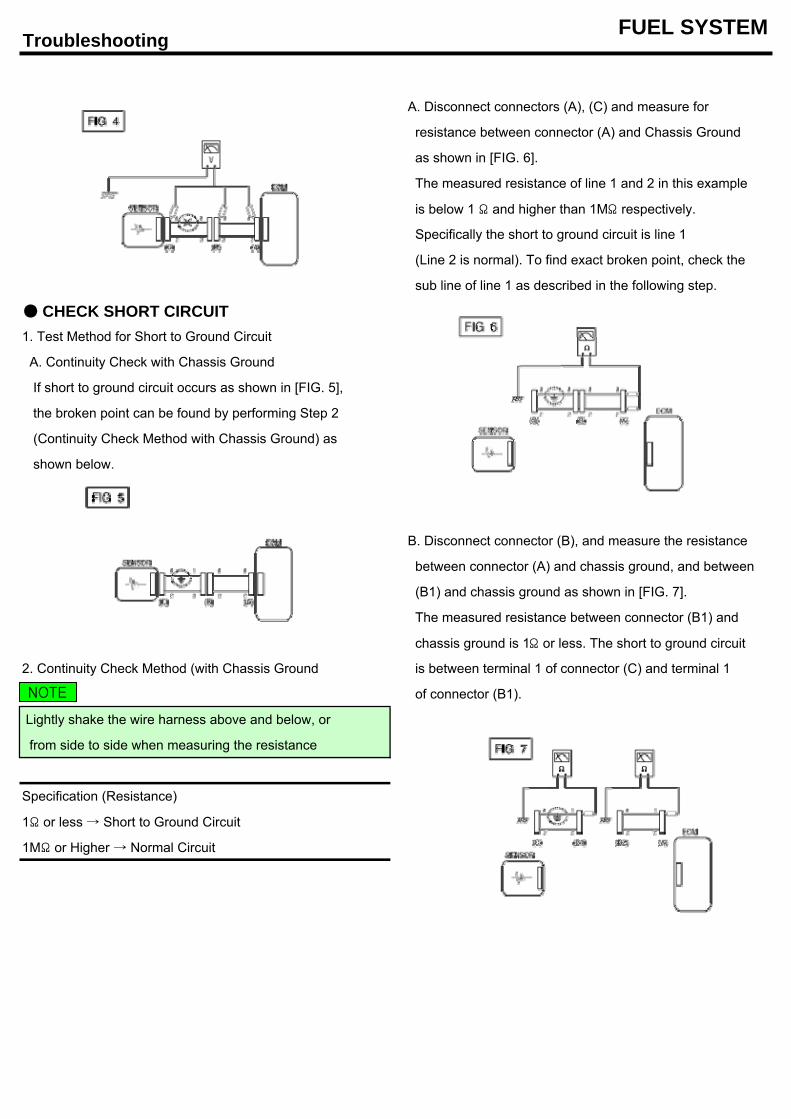
Troubleshooting FUEL SYSTEM
A. Disconnect connectors (A), (C) and measure for
resistance between connector (A) and Chassis Ground
as shown in [FIG. 6].
The measured resistance of line 1 and 2 in this example
is below 1 Ω and higher than 1MΩ respectively.
Specifically the short to ground circuit is line 1
(Line 2 is normal). To find exact broken point, check the
sub line of line 1 as described in the following step.
CHECK SHORT CIRCUIT1. Test Method for Short to Ground Circuit
A. Continuity Check with Chassis Ground
If short to ground circuit occurs as shown in [FIG. 5],
the broken point can be found by performing Step 2
(Continuity Check Method with Chassis Ground) as
shown below.
B. Disconnect connector (B), and measure the resistance
between connector (A) and chassis ground, and between
(B1) and chassis ground as shown in [FIG. 7].
The measured resistance between connector (B1) and
chassis ground is 1Ω or less. The short to ground circuit
2. Continuity Check Method (with Chassis Ground is between terminal 1 of connector (C) and terminal 1
of connector (B1).
Lightly shake the wire harness above and below, or
from side to side when measuring the resistance
Specification (Resistance)
1Ω or less → Short to Ground Circuit
1MΩ or Higher → Normal Circuit
NOTE
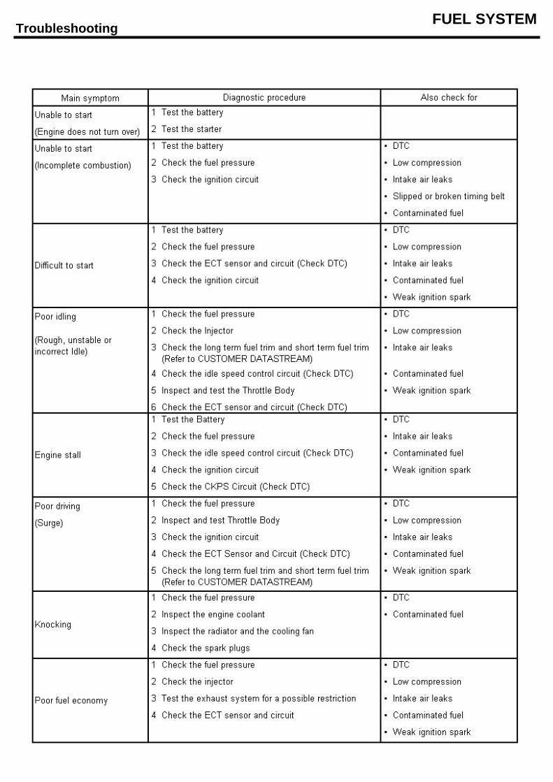
Troubleshooting FUEL SYSTEM
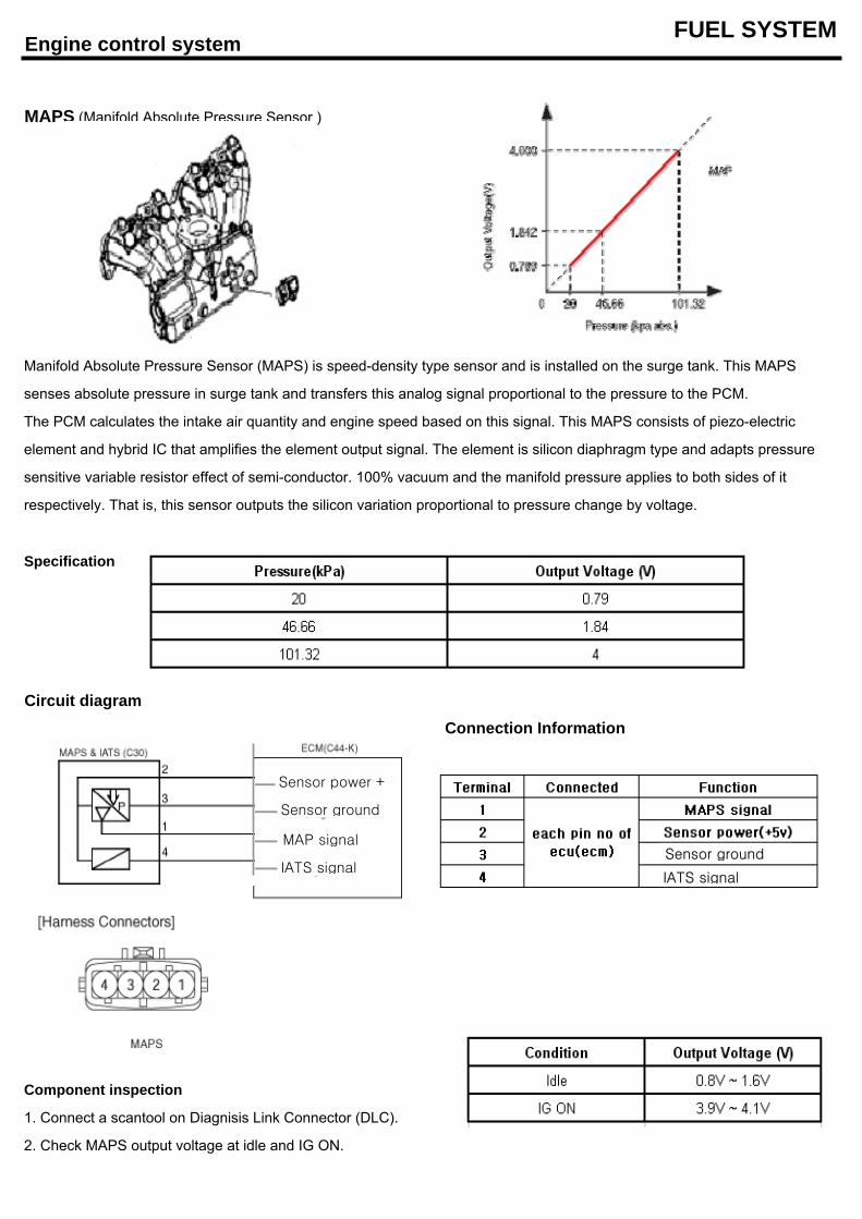
Engine control system FUEL SYSTEM
MAPS (Manifold Absolute Pressure Sensor )
Specification
Circuit diagram
Component inspection
1. Connect a scantool on Diagnisis Link Connector (DLC).
2. Check MAPS output voltage at idle and IG ON.
sensitive variable resistor effect of semi-conductor. 100% vacuum and the manifold pressure applies to both sides of it
respectively. That is, this sensor outputs the silicon variation proportional to pressure change by voltage.
Manifold Absolute Pressure Sensor (MAPS) is speed-density type sensor and is installed on the surge tank. This MAPS
senses absolute pressure in surge tank and transfers this analog signal proportional to the pressure to the PCM.
The PCM calculates the intake air quantity and engine speed based on this signal. This MAPS consists of piezo-electric
element and hybrid IC that amplifies the element output signal. The element is silicon diaphragm type and adapts pressure
Connection Information
IATS signal
Sensor groundIATS signal
Sensor power +
Sensor ground
MAP signal
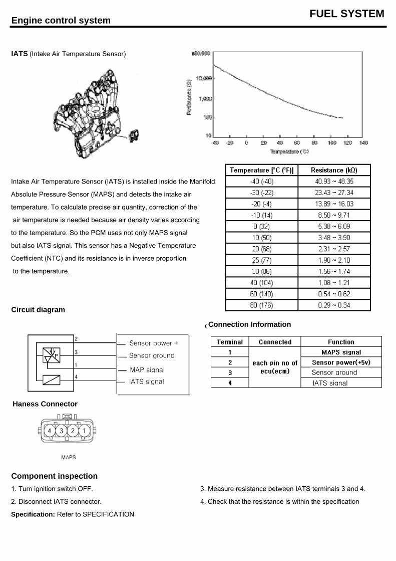
Engine control system FUEL SYSTEM
IATS (Intake Air Temperature Sensor)
Intake Air Temperature Sensor (IATS) is installed inside the Manifold
Absolute Pressure Sensor (MAPS) and detects the intake air
temperature. To calculate precise air quantity, correction of the
air temperature is needed because air density varies according
to the temperature. So the PCM uses not only MAPS signal
but also IATS signal. This sensor has a Negative Temperature
Coefficient (NTC) and its resistance is in inverse proportion
to the temperature.
Circuit diagram
Component inspection1. Turn ignition switch OFF. 3. Measure resistance between IATS terminals 3 and 4.
2. Disconnect IATS connector. 4. Check that the resistance is within the specification
Specification: Refer to SPECIFICATION
Connection InformationConnection Information
IATS signal
Sensor ground
IATS signal
Sensor power +
Sensor ground
MAP signal
Haness Connector
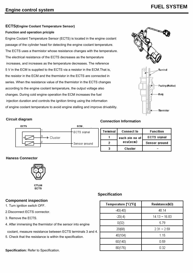
Engine control system FUEL SYSTEM
ECTS(Engine Coolant Temperature Sensor)
Function and operation priciple
Engine Coolant Temperature Sensor (ECTS) is located in the engine coolant
passage of the cylinder head for detecting the engine coolant temperature.
The ECTS uses a thermistor whose resistance changes with the temperature.
The electrical resistance of the ECTS decreases as the temperature
increases, and increases as the temperature decreases. The reference
5 V in the ECM is supplied to the ECTS via a resistor in the ECM.That is,
the resistor in the ECM and the thermistor in the ECTS are connected in
series. When the resistance value of the thermistor in the ECTS changes
according to the engine coolant temperature, the output voltage also
changes. During cold engine operation the ECM increases the fuel
injection duration and controls the ignition timing using the information
of engine coolant temperature to avoid engine stalling and improve drivability.
SpecificationComponent inspection1. Turn ignition switch OFF.
2.Disconnect ECTS connector.
3. Remove the ECTS.
4. After immersing the thermistor of the sensor into engine
coolant, measure resistance between ECTS terminals 3 and 4.5. Check that the resistance is within the specification.
Specification: Refer to Specification.
Connection InformationCircuit diagram
Haness Connector
Cluster
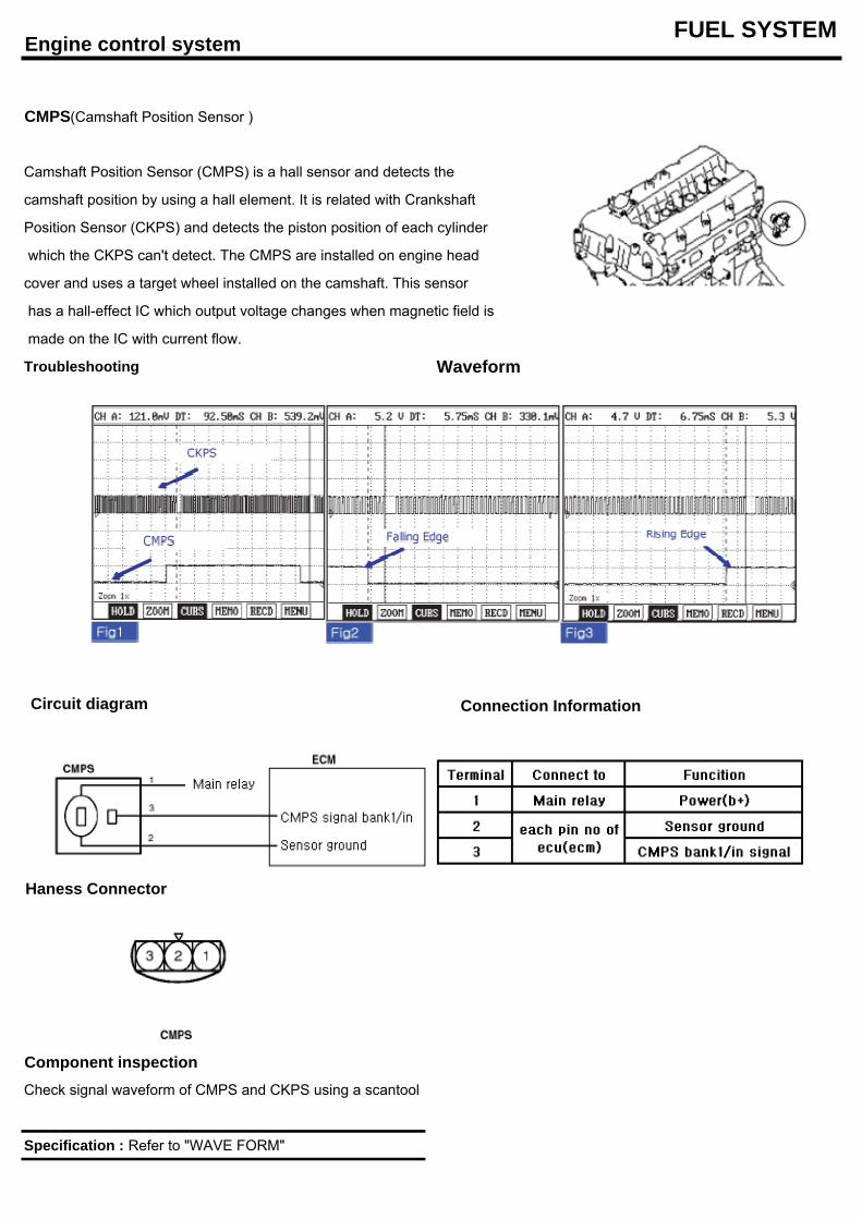
Engine control system FUEL SYSTEM
CMPS(Camshaft Position Sensor )
Camshaft Position Sensor (CMPS) is a hall sensor and detects the
camshaft position by using a hall element. It is related with Crankshaft
Position Sensor (CKPS) and detects the piston position of each cylinder
which the CKPS can't detect. The CMPS are installed on engine head
cover and uses a target wheel installed on the camshaft. This sensor
has a hall-effect IC which output voltage changes when magnetic field is
made on the IC with current flow.
Troubleshooting Waveform
Component inspectionCheck signal waveform of CMPS and CKPS using a scantool
Specification : Refer to "WAVE FORM"
Circuit diagram Connection Information
Haness Connector
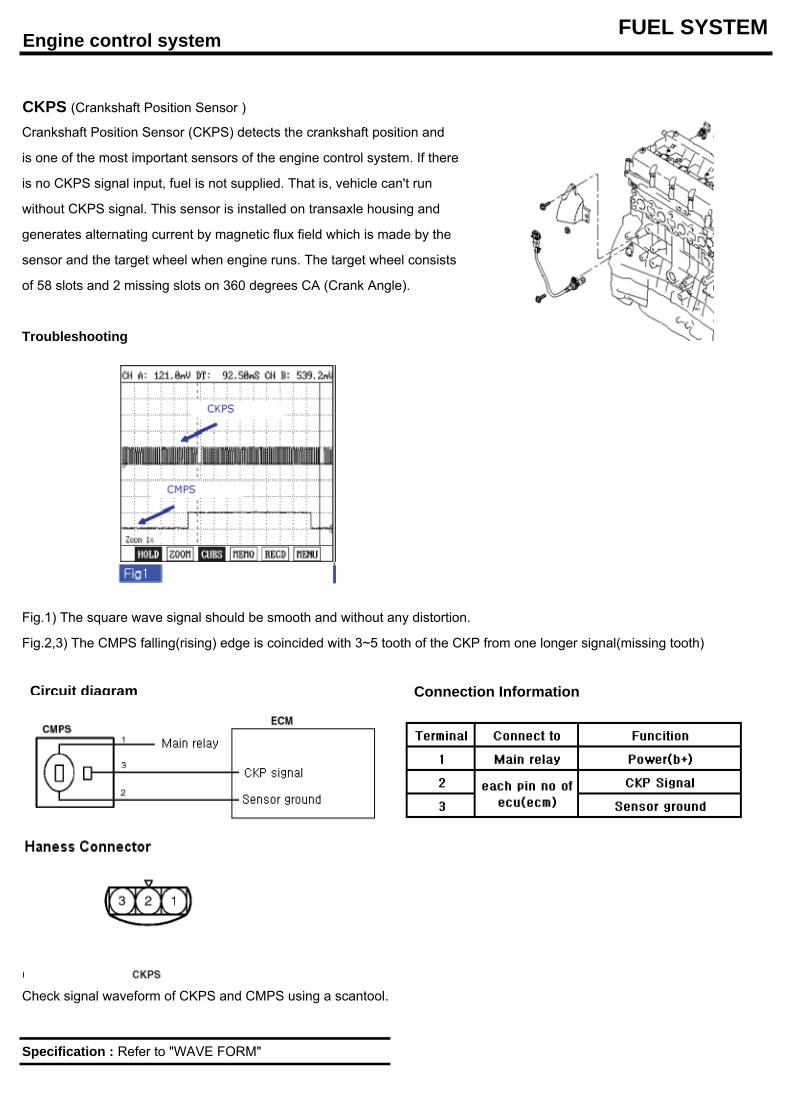
Engine control system FUEL SYSTEM
CKPS (Crankshaft Position Sensor )
Crankshaft Position Sensor (CKPS) detects the crankshaft position and
is one of the most important sensors of the engine control system. If there
is no CKPS signal input, fuel is not supplied. That is, vehicle can't run
without CKPS signal. This sensor is installed on transaxle housing and
generates alternating current by magnetic flux field which is made by the
sensor and the target wheel when engine runs. The target wheel consists
of 58 slots and 2 missing slots on 360 degrees CA (Crank Angle).
Troubleshooting
Fig.1) The square wave signal should be smooth and without any distortion.
Fig.2,3) The CMPS falling(rising) edge is coincided with 3~5 tooth of the CKP from one longer signal(missing tooth)
Component inspection
Specification : Refer to "WAVE FORM"
Check signal waveform of CKPS and CMPS using a scantool.
Connection Information
Haness Connector
CKP signal
Circuit diagram
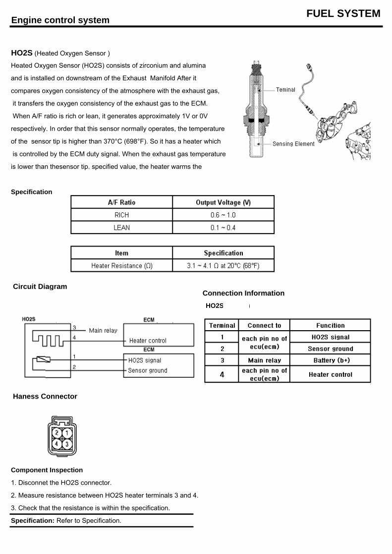
Engine control system FUEL SYSTEM
HO2S (Heated Oxygen Sensor )
Heated Oxygen Sensor (HO2S) consists of zirconium and alumina
and is installed on downstream of the Exhaust Manifold After it
compares oxygen consistency of the atmosphere with the exhaust gas,
it transfers the oxygen consistency of the exhaust gas to the ECM.
When A/F ratio is rich or lean, it generates approximately 1V or 0V
respectively. In order that this sensor normally operates, the temperature
of the sensor tip is higher than 370°C (698°F). So it has a heater which
is controlled by the ECM duty signal. When the exhaust gas temperature
is lower than thesensor tip. specified value, the heater warms the
Specification
Connection Information HO2S 9B1/S1)
Component Inspection
1. Disconnet the HO2S connector.
2. Measure resistance between HO2S heater terminals 3 and 4.
3. Check that the resistance is within the specification.
Specification: Refer to Specification.
Circuit Diagram
Haness Connector
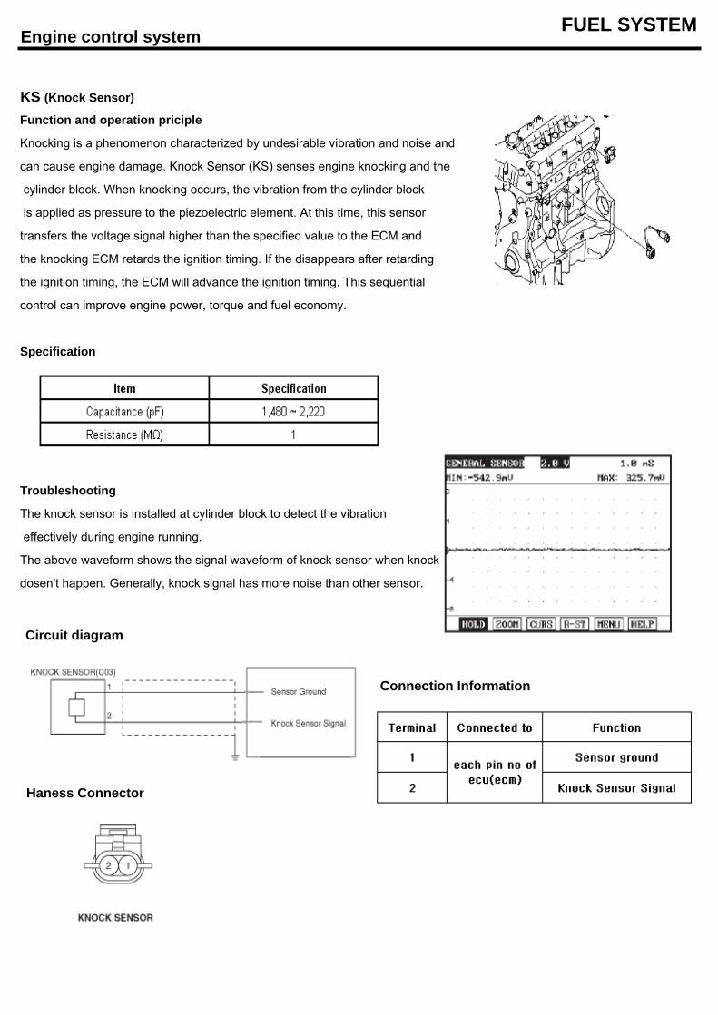
Engine control system FUEL SYSTEM
KS (Knock Sensor)
Function and operation priciple
Knocking is a phenomenon characterized by undesirable vibration and noise and
can cause engine damage. Knock Sensor (KS) senses engine knocking and the
cylinder block. When knocking occurs, the vibration from the cylinder block
is applied as pressure to the piezoelectric element. At this time, this sensor
transfers the voltage signal higher than the specified value to the ECM and
the knocking ECM retards the ignition timing. If the disappears after retarding
the ignition timing, the ECM will advance the ignition timing. This sequential
control can improve engine power, torque and fuel economy.
Specification
Troubleshooting
The knock sensor is installed at cylinder block to detect the vibration
effectively during engine running.
The above waveform shows the signal waveform of knock sensor when knock
dosen't happen. Generally, knock signal has more noise than other sensor.
Haness Connector
Circuit diagram
Connection Information
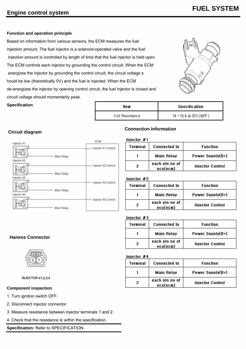
Engine control system FUEL SYSTEM
Function and operation principle
Based on information from various sensors, the ECM measures the fuel
injection amount. The fuel injector is a solenoid-operated valve and the fuel
injection amount is controlled by length of time that the fuel injector is held open.
The ECM controls each injector by grounding the control circuit. When the ECM
energizes the injector by grounding the control circuit, the circuit voltage s
hould be low (theoretically 0V) and the fuel is injected. When the ECM
de-energizes the injector by opening control circuit, the fuel injector is closed and
circuit voltage should momentarily peak.
Specification
Connection Information
Component inspection
1. Turn ignition switch OFF.
2. Disconnect injector connector.
3. Measure resistance between injector terminals 1 and 2.
4. Check that the resistance is within the specification.
Specification: Refer to SPECIFICATION.
Circuit diagram
Haness Connector