Embed Size (px)
Citation preview
Chapter 3
Engine Design and Operation
Objectives (1 of 2)
• Upon completion and review of this chapter, you should be able to: – Define the methods used for engine classification.– Describe the four strokes in the four-stroke engine.– Explain compression ratio.– Explain the purpose of the camshaft, pushrods, and rocker arms.– Explain volumetric efficiency.– Describe the difference between an overhead cam and an
overhead valve engine.– Describe the different types of engine block design.– Briefly describe the different engine systems.– Define cylinder bore and stroke.
Objectives (2 of 2)
• Upon completion and review of this chapter, you should be able to: – Explain how to calculate engine displacement.– Describe three different methods of measuring engine efficiency.– Name and describe the components of a typical lubricating
system.– Describe the purpose of a crankcase ventilation system. – Explain oil service and viscosity ratings.– List and describe the major components of the cooling system.– Describe the function of the water pump, radiator, radiator cap,
and thermostat in the cooling system.
Introduction
• Modern engines are highly engineered power plants.
• Modern engines are:– Compact– Lightweight– Fuel efficient
Engine Classifications
• Operational cycles• Number of cylinders• Cylinder arrangement• Displacement• Valvetrain type• Ignition type• Cooling system• Fuel type
Engine Location
• Front-mounted
• Mid-mounted
• Rear-mounted
Engine Block Configurations
• In-Line Engines
• V-Type Engines
• Slant Cylinder Engines
• Opposed Cylinder Engines
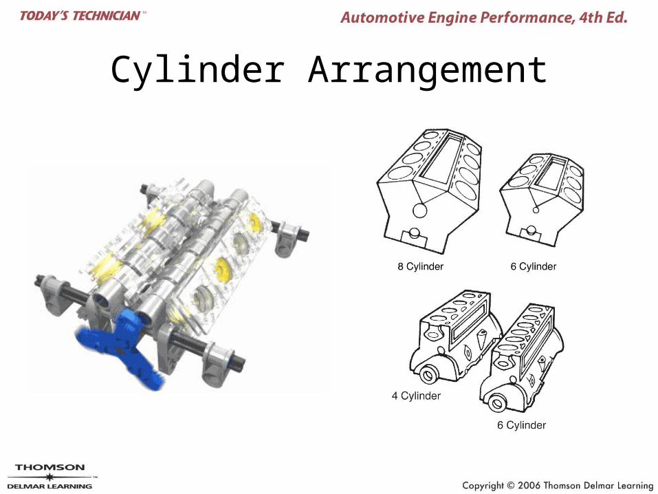
Cylinder Arrangement
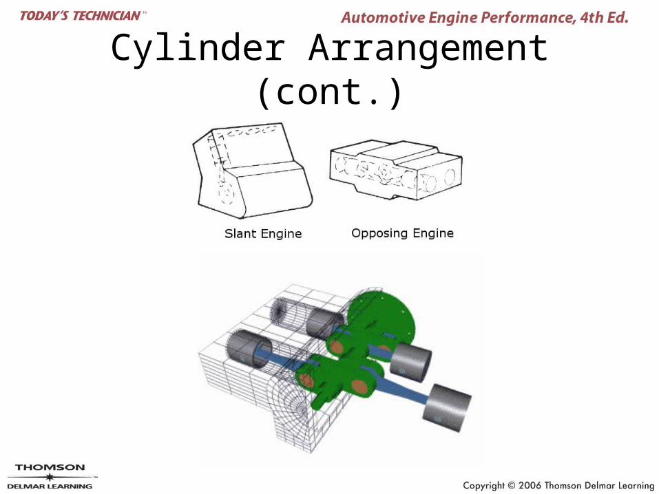
Cylinder Arrangement (cont.)
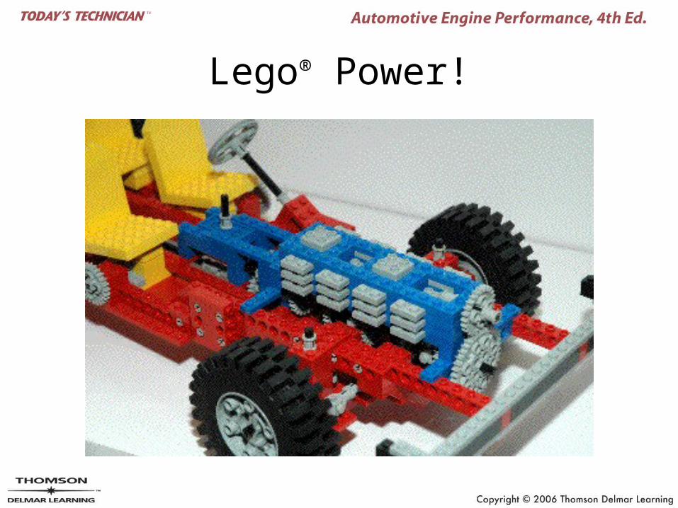
Lego® Power!
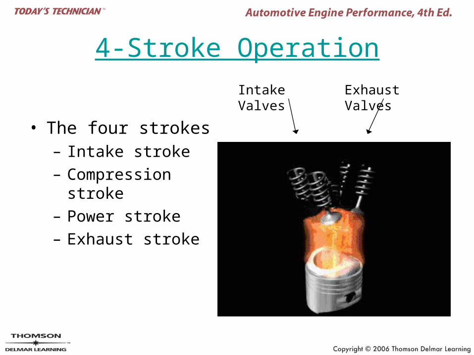
4-Stroke Operation
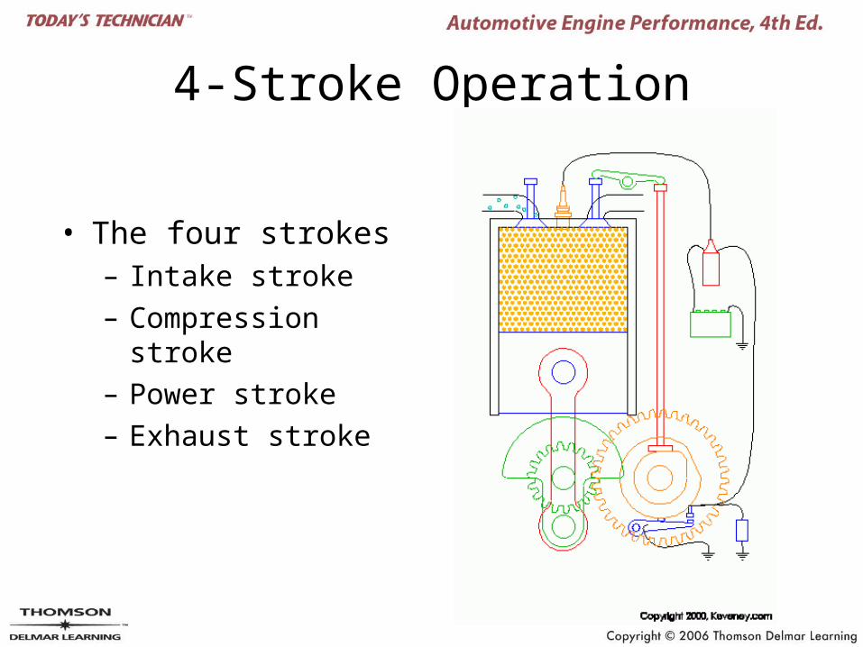
• The four strokes– Intake stroke– Compression stroke– Power stroke– Exhaust stroke
Intake Valves Exhaust Valves
4-Stroke Operation
• The four strokes– Intake stroke– Compression stroke– Power stroke– Exhaust stroke
Intake Stroke
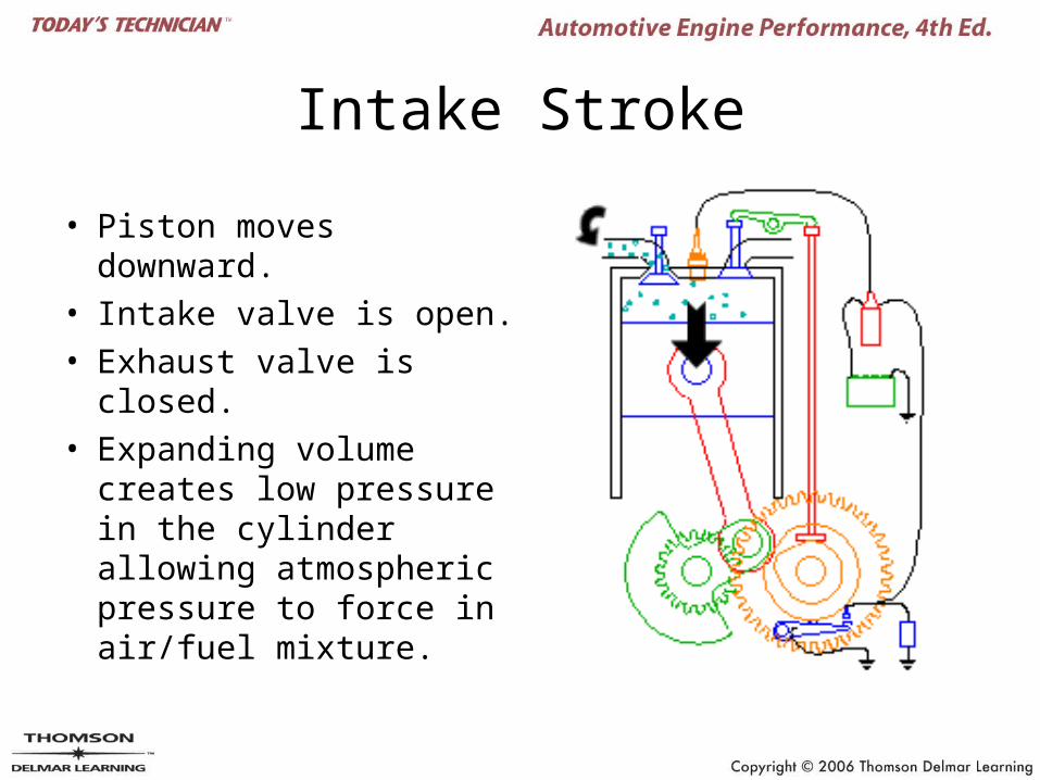
• Piston moves downward.
• Intake valve is open.
• Exhaust valve is closed.
• Expanding volume creates low pressure in the cylinder allowing atmospheric pressure to force in air/fuel mixture.
Compression Stroke
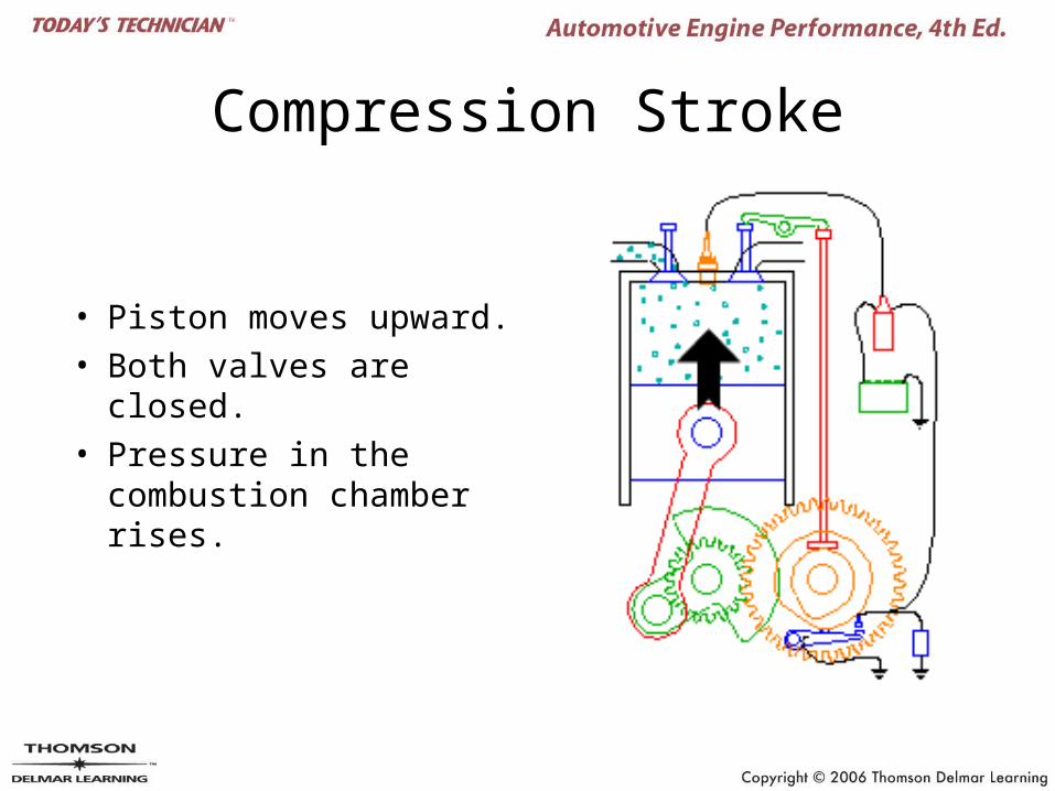
• Piston moves upward.
• Both valves are closed.
• Pressure in the combustion chamber rises.
Power Stroke
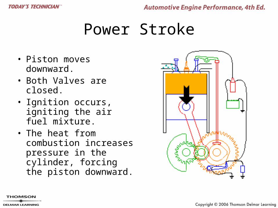
• Piston moves downward.
• Both Valves are closed.• Ignition occurs, igniting
the air fuel mixture.• The heat from
combustion increases pressure in the cylinder, forcing the piston downward.
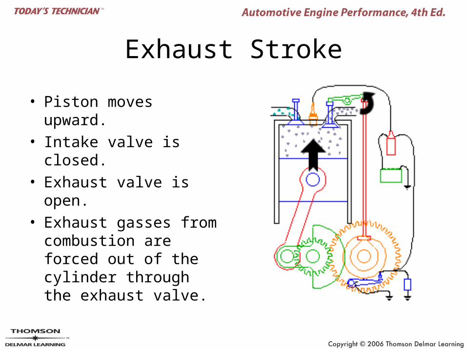
Exhaust Stroke
• Piston moves upward.
• Intake valve is closed.
• Exhaust valve is open.
• Exhaust gasses from combustion are forced out of the cylinder through the exhaust valve.
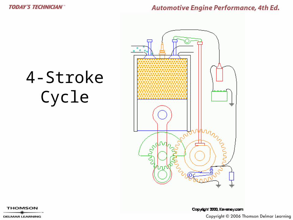
4-Stroke Cycle
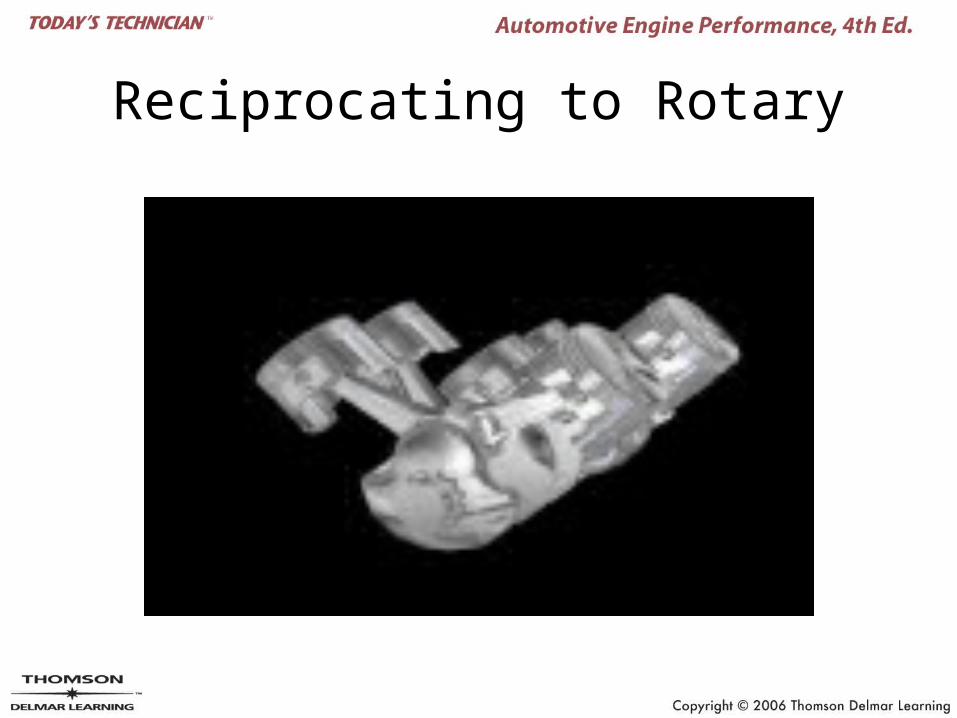
Reciprocating to Rotary
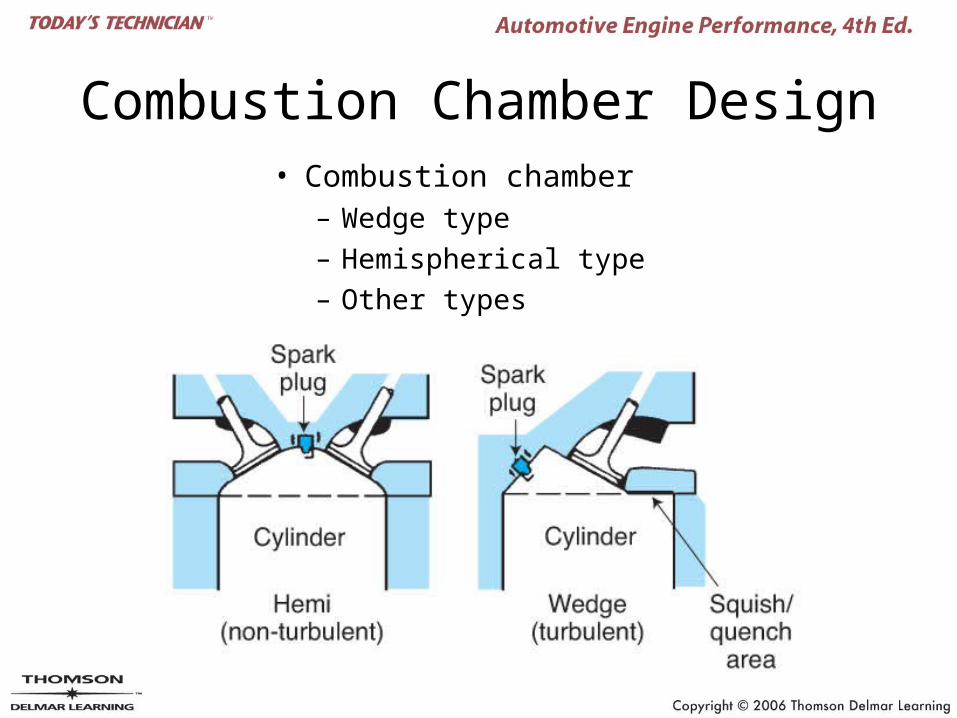
Combustion Chamber Design• Combustion chamber
– Wedge type– Hemispherical type– Other types
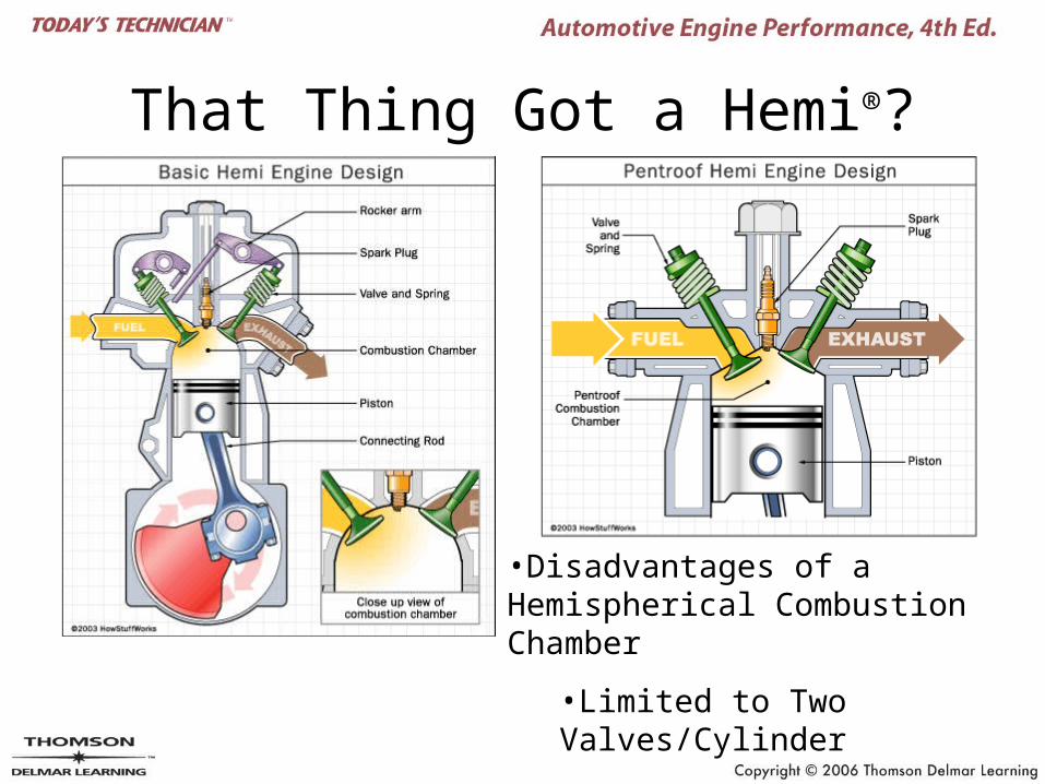
That Thing Got a Hemi®?
•Disadvantages of a Hemispherical Combustion Chamber
•Limited to Two Valves/Cylinder
•Large Combustion Chamber
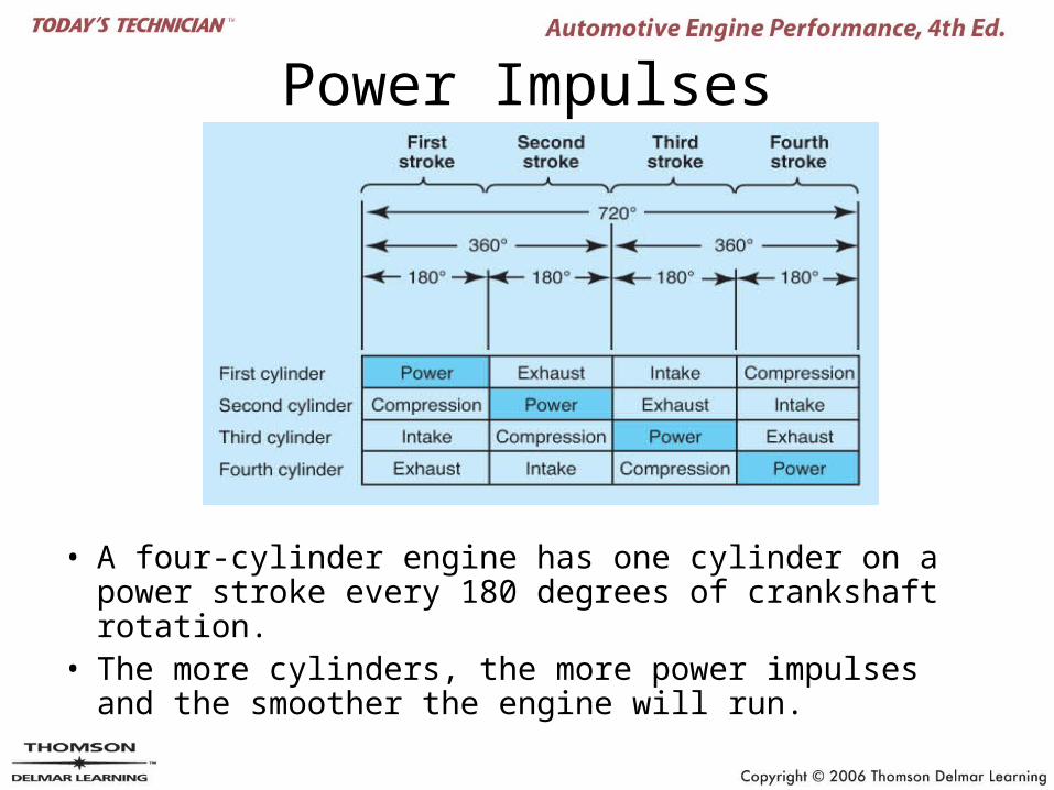
Power Impulses
• A four-cylinder engine has one cylinder on a power stroke every 180 degrees of crankshaft rotation.
• The more cylinders, the more power impulses and the smoother the engine will run.
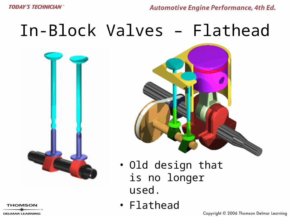
In-Block Valves – Flathead
• Old design that is no longer used.
• Flathead
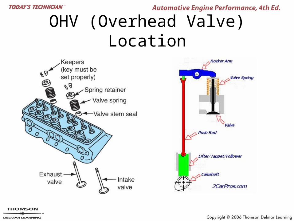
OHV (Overhead Valve) Location
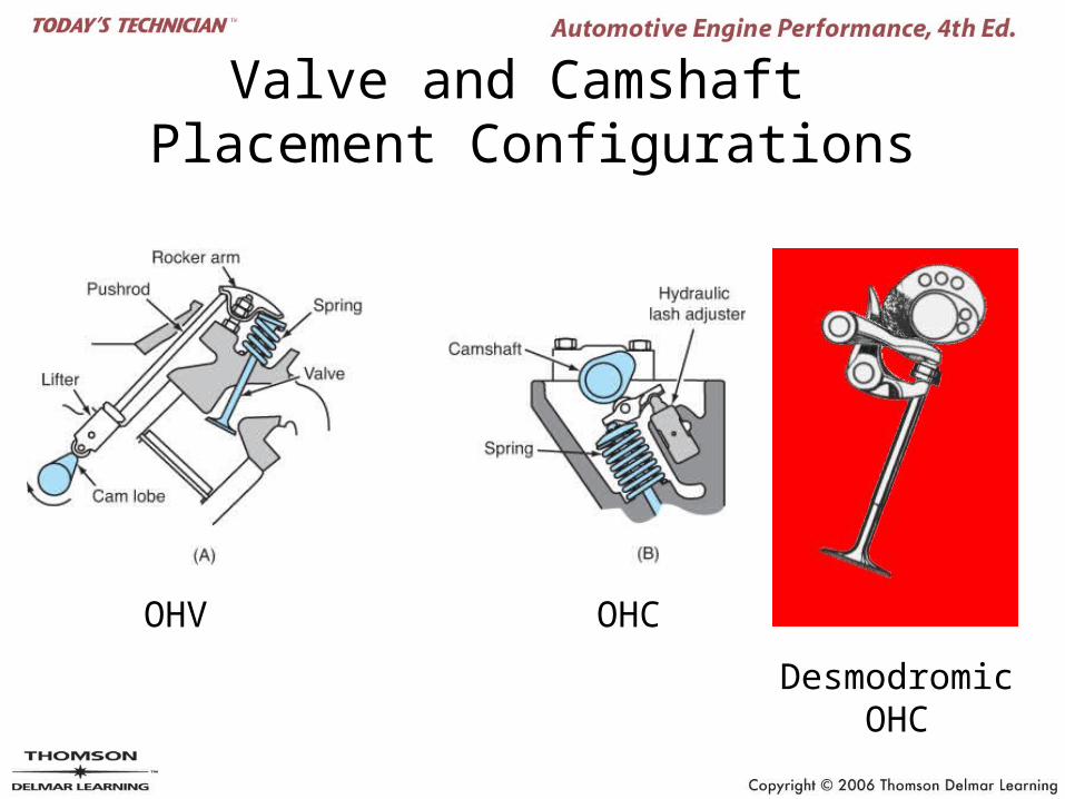
Valve and Camshaft Placement Configurations
OHV OHC
Desmodromic OHC
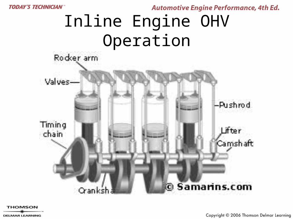
Inline Engine OHV Operation
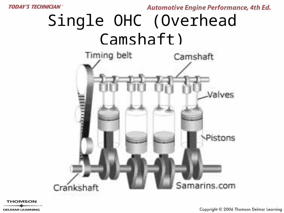
Single OHC (Overhead Camshaft)
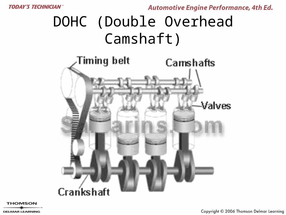
DOHC (Double Overhead Camshaft)
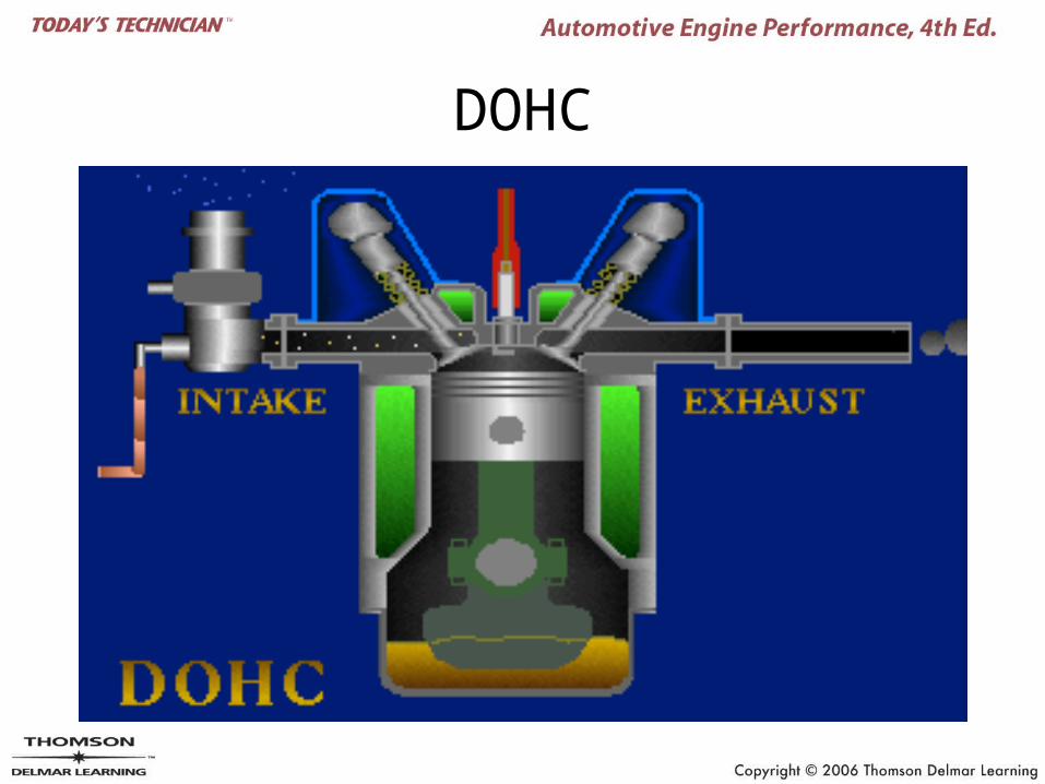
DOHC
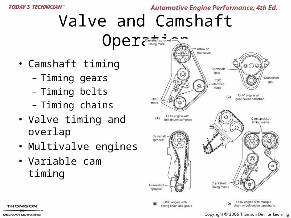
Valve and Camshaft Operation
• Camshaft timing– Timing gears– Timing belts– Timing chains
• Valve timing and overlap
• Multivalve engines
• Variable cam timing
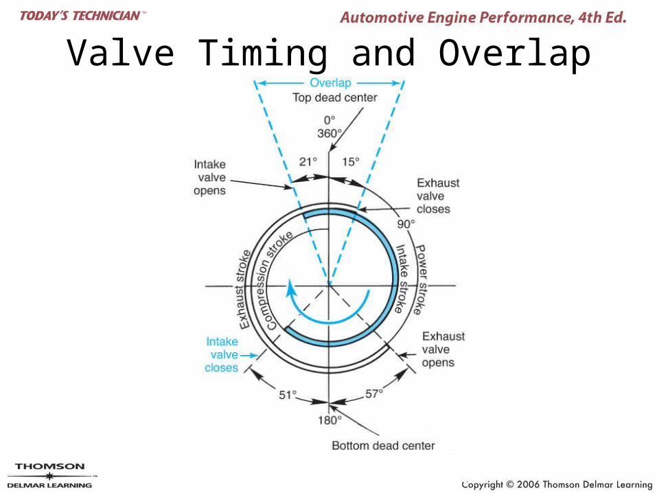
Valve Timing and Overlap
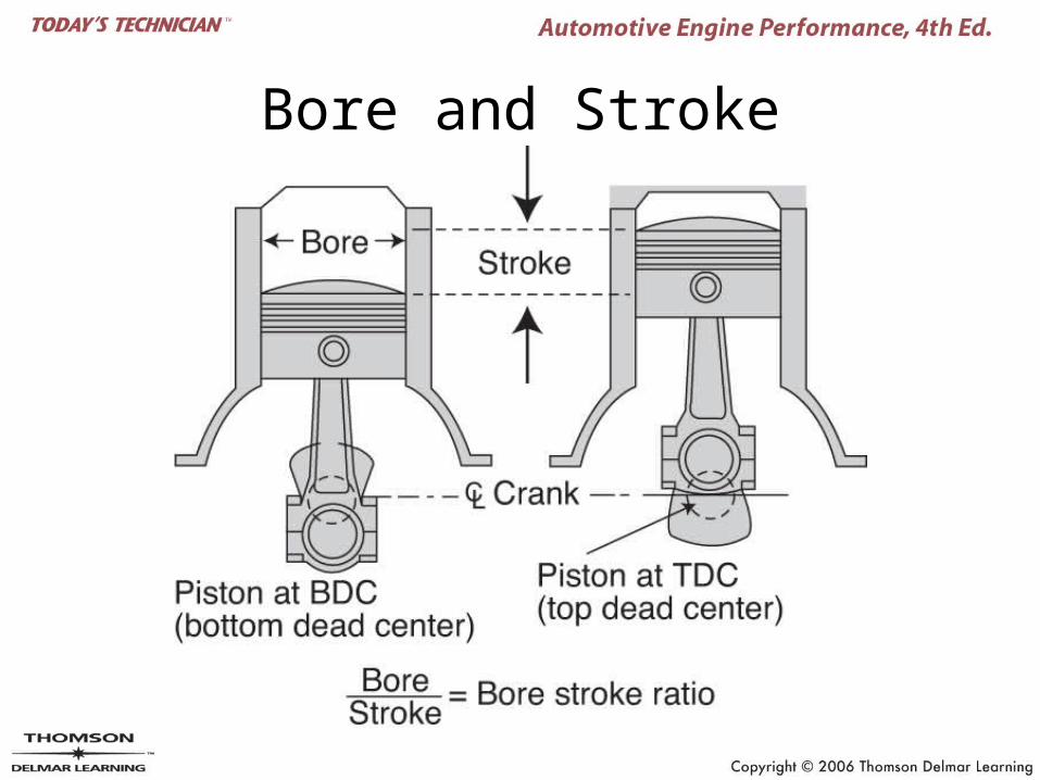
Bore and Stroke
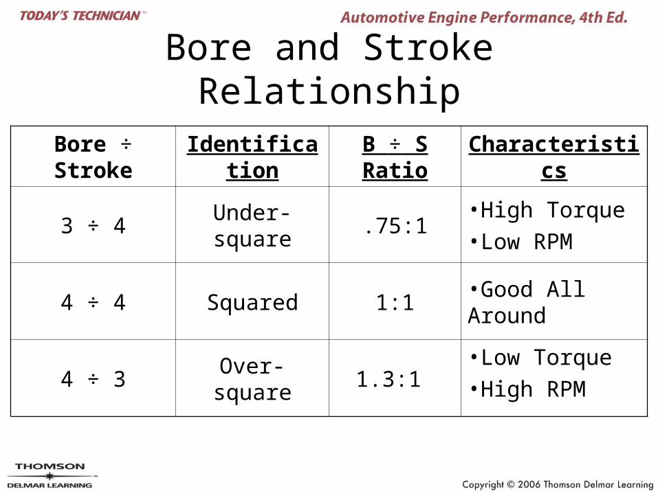
Bore and Stroke Relationship
Bore ÷ Stroke Identification B ÷ S Ratio Characteristics
3 ÷ 4 Under-square .75:1•High Torque•Low RPM
4 ÷ 4 Squared 1:1 •Good All Around
4 ÷ 3 Over-square 1.3:1 •Low Torque•High RPM
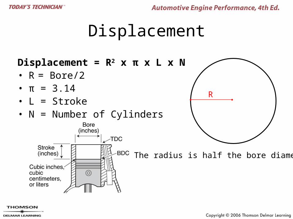
Displacement
Displacement = R2 x π x L x N• R = Bore/2• π = 3.14• L = Stroke• N = Number of Cylinders
R
The radius is half the bore diameter.
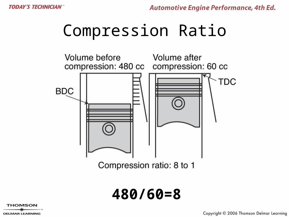
Compression Ratio
480/60=8
Engine Efficiency
• Thermal efficiency– 35% loss to cooling and lubrication systems– 35% loss to exhaust gasses– 5% loss to engine friction– 10% loss to powertrain friction
• Mechanical efficiency
• Volumetric efficiency
Torque and Horsepower (1 of 2)
• Torque = Force x Radius
• Brake horsepower– The useable power at the engine’s crankshaft
• Friction horsepower– The power required to overcome the internal
friction of the engine
Torque and Horsepower (2 of 2)
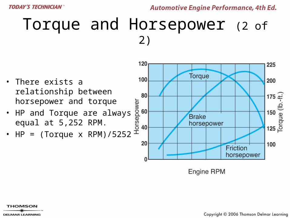
• There exists a relationship between horsepower and torque
• HP and Torque are always equal at 5,252 RPM.
• HP = (Torque x RPM)/5252
Other Engine Designs
• Atkinson cycle engine• Two-stroke gasoline
engines• Diesel engines• Rotary engines• Stratified charge engines• Miller-cycle engines• Electric motors• Hybrid electric vehicles• Fuel cells
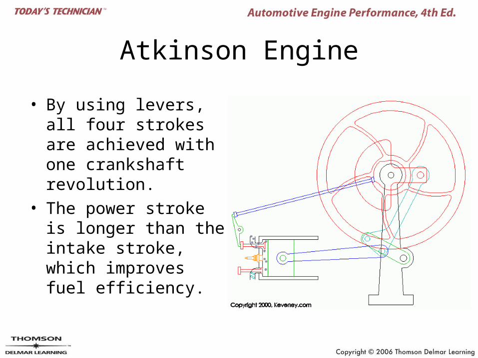
Atkinson Engine
• By using levers, all four strokes are achieved with one crankshaft revolution.
• The power stroke is longer than the intake stroke, which improves fuel efficiency.
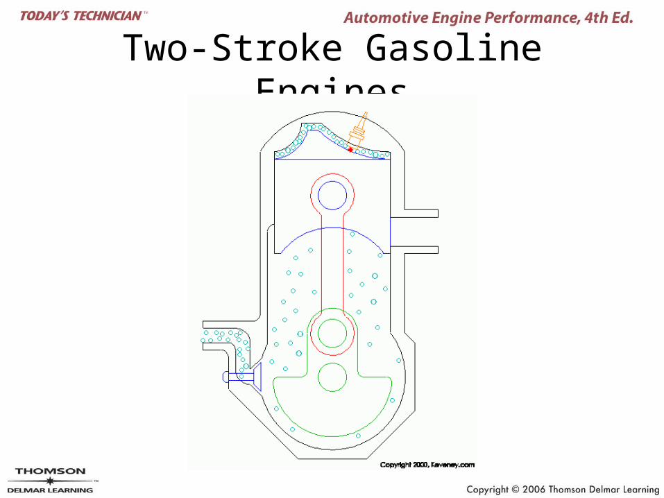
Two-Stroke Gasoline Engines
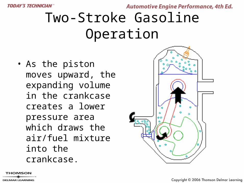
Two-Stroke Gasoline Operation
• As the piston moves upward, the expanding volume in the crankcase creates a lower pressure area which draws the air/fuel mixture into the crankcase.
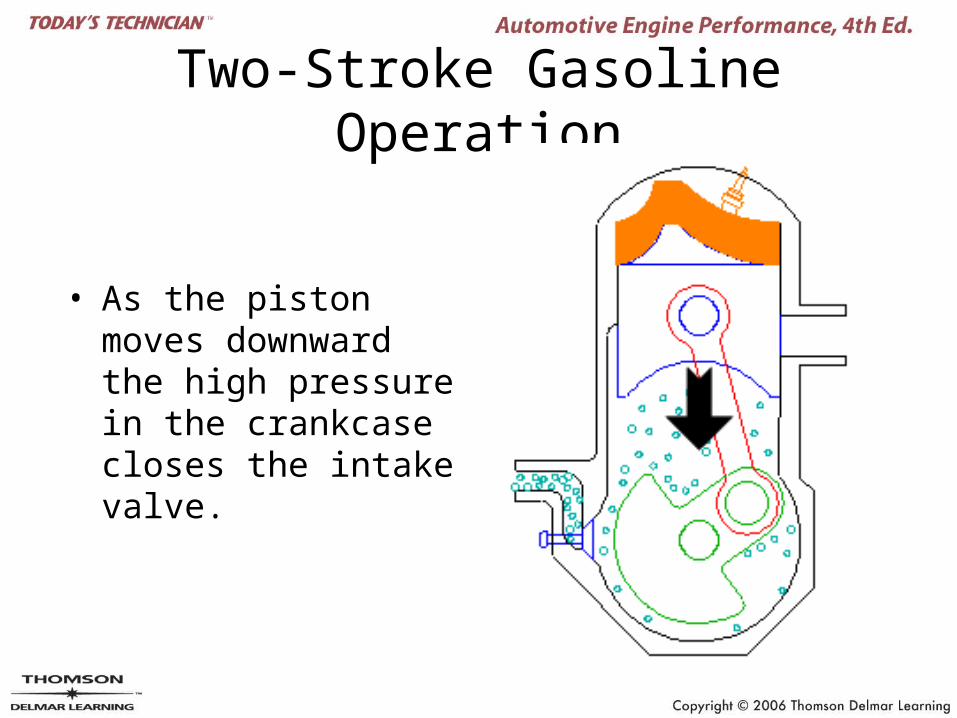
Two-Stroke Gasoline Operation
• As the piston moves downward the high pressure in the crankcase closes the intake valve.
Two-Stroke Gasoline Operation
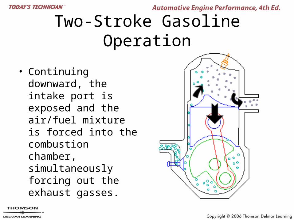
• Continuing downward, the intake port is exposed and the air/fuel mixture is forced into the combustion chamber, simultaneously forcing out the exhaust gasses.
Two-Stroke Gasoline Operation
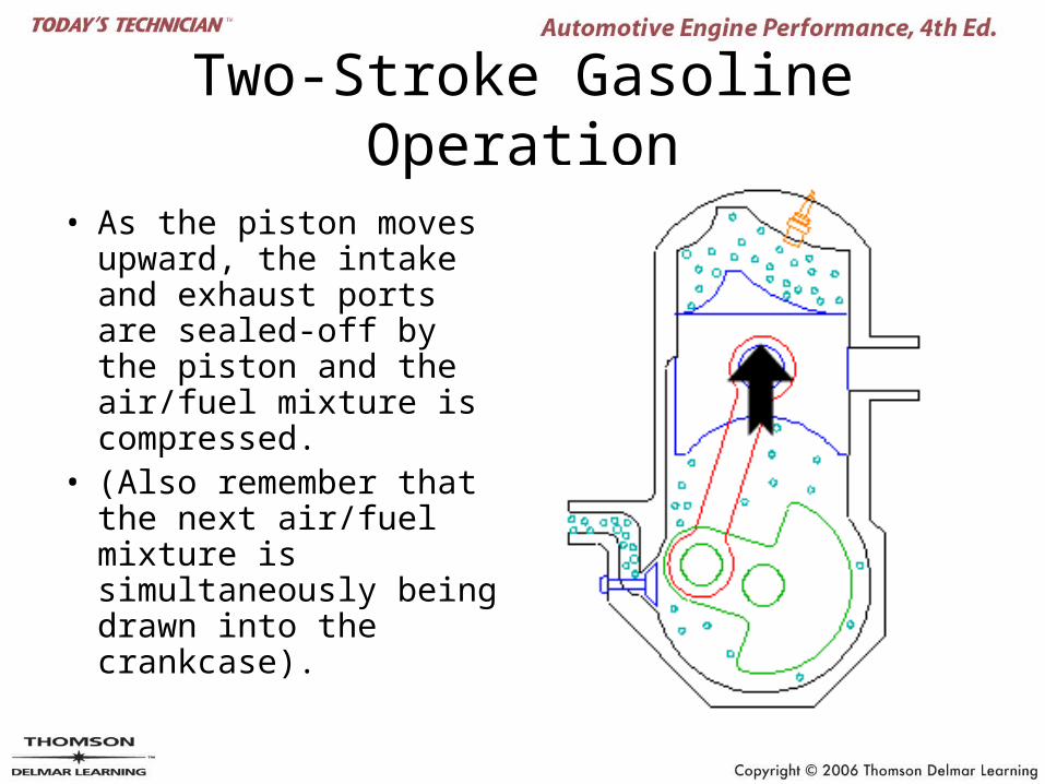
• As the piston moves upward, the intake and exhaust ports are sealed-off by the piston and the air/fuel mixture is compressed.
• (Also remember that the next air/fuel mixture is simultaneously being drawn into the crankcase).
Two-Stroke Gasoline Operation
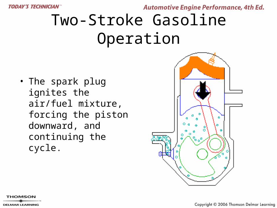
• The spark plug ignites the air/fuel mixture, forcing the piston downward, and continuing the cycle.
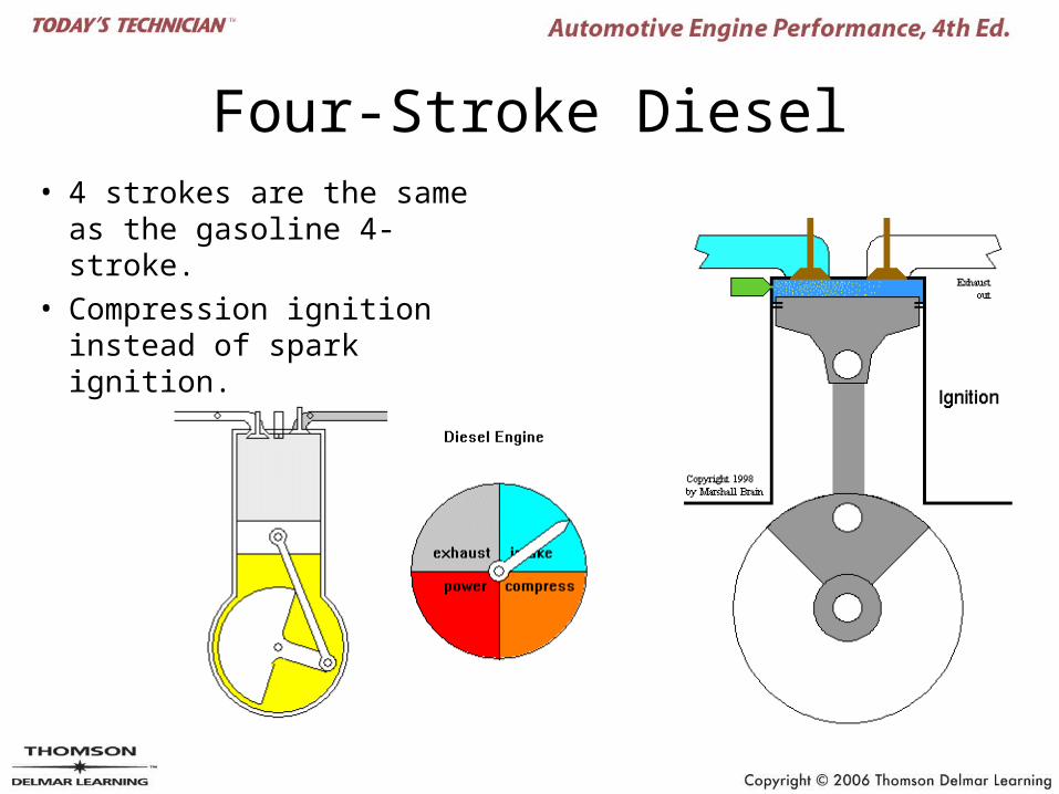
Four-Stroke Diesel• 4 strokes are the same
as the gasoline 4-stroke.
• Compression ignition instead of spark ignition.
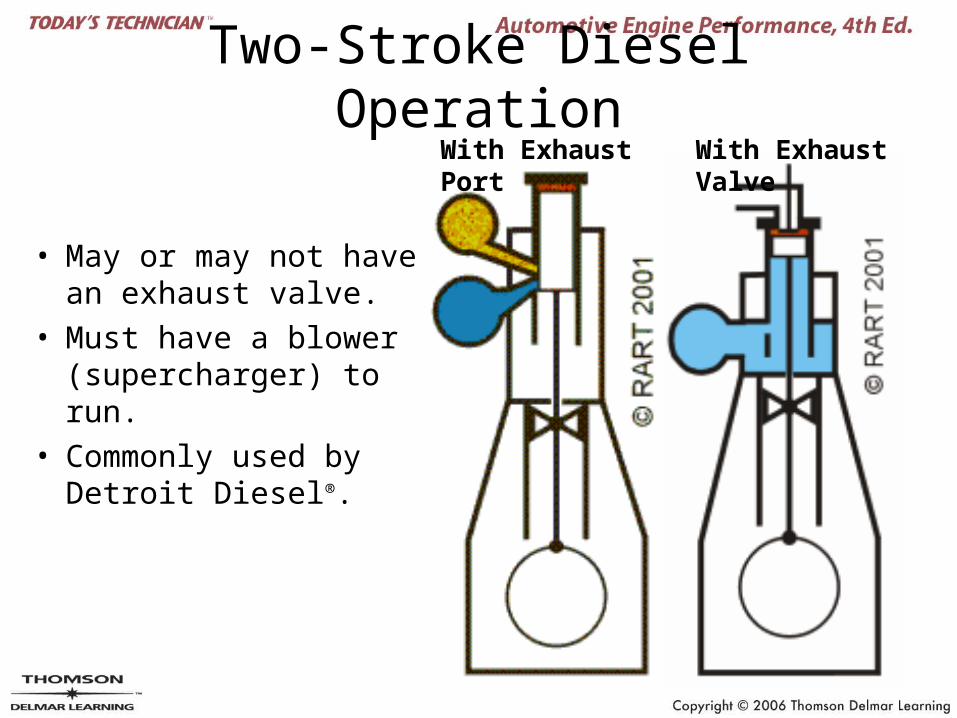
Two-Stroke Diesel Operation
• May or may not have an exhaust valve.
• Must have a blower (supercharger) to run.
• Commonly used by Detroit Diesel®.
With Exhaust Port With Exhaust Valve
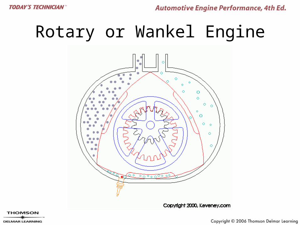
Rotary or Wankel Engine
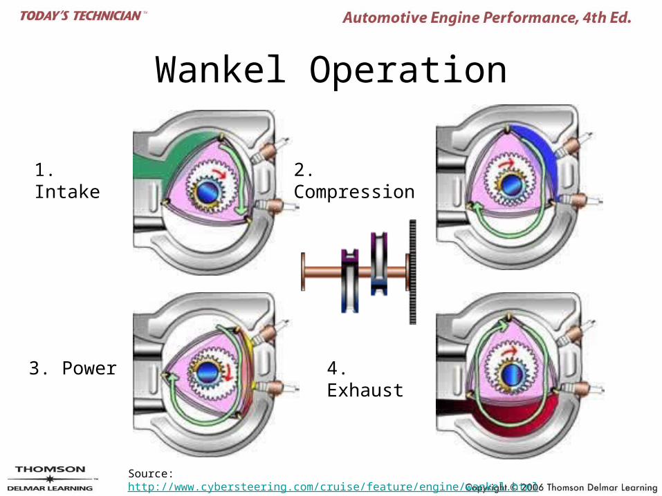
Wankel Operation
1. Intake 2. Compression
3. Power 4. Exhaust
Source: http://www.cybersteering.com/cruise/feature/engine/wankel.html
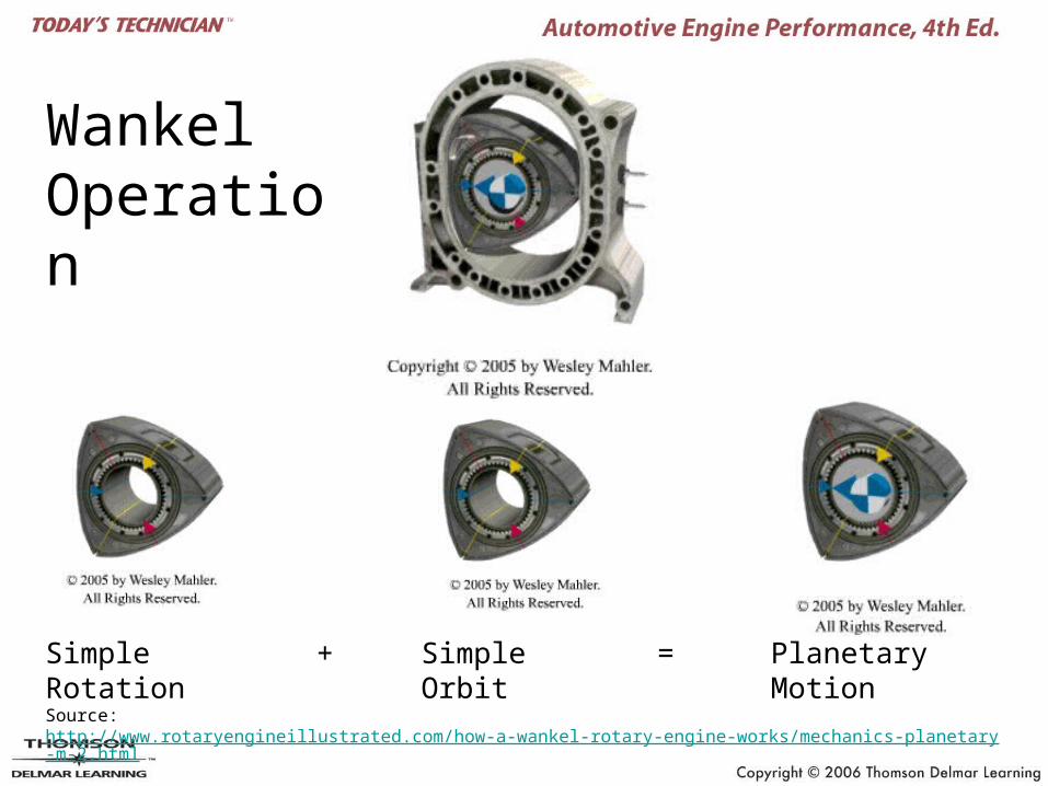
Wankel Operation
Source: http://www.rotaryengineillustrated.com/how-a-wankel-rotary-engine-works/mechanics-planetary-m-2.html
Simple Rotation + Simple Orbit = Planetary Motion
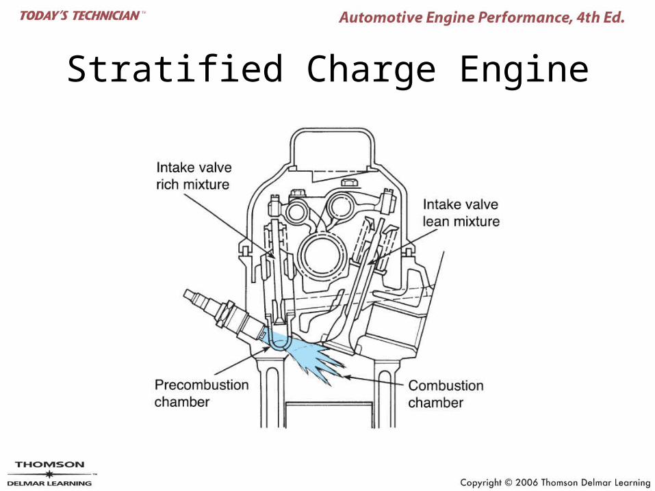
Stratified Charge Engine
Miller-Cycle Engine
• A Miller-cycle engine depends on a supercharger.
• A Miller-cycle engine leaves the intake valve open during part of the compression stroke, so that the engine is compressing against the pressure of the supercharger rather than the pressure of the cylinder walls. The effect is increased efficiency, at a level of about 15 percent.
Source: http://auto.howstuffworks.com/question132.htm
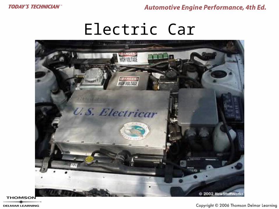
Electric Car
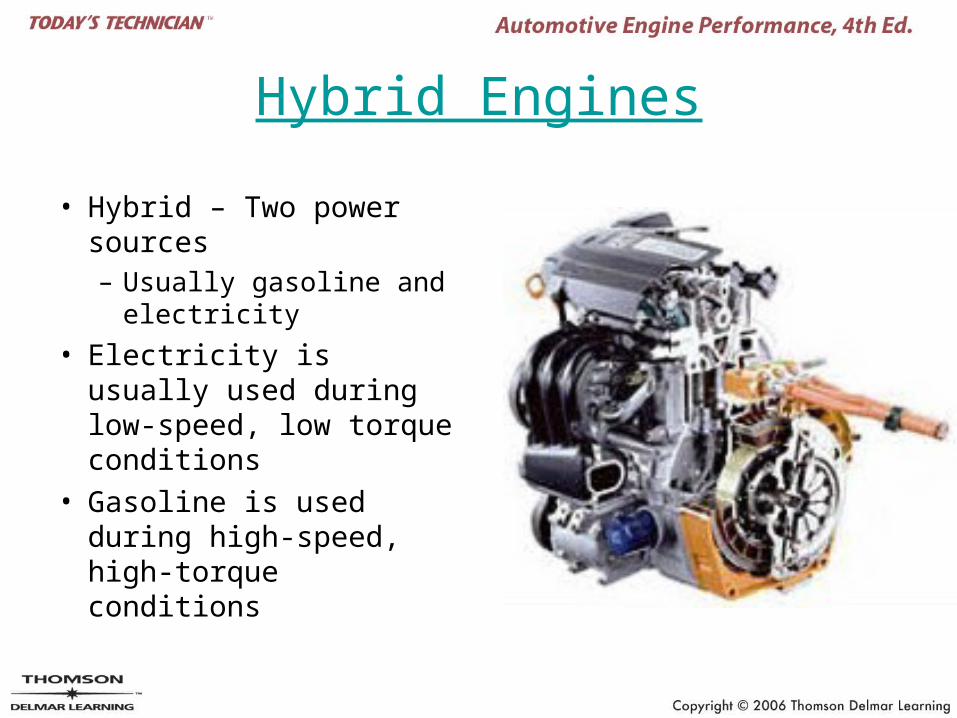
Hybrid Engines
• Hybrid – Two power sources– Usually gasoline and
electricity
• Electricity is usually used during low-speed, low torque conditions
• Gasoline is used during high-speed, high-torque conditions
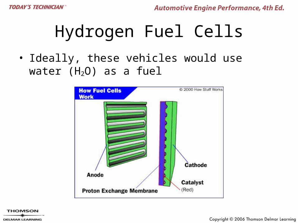
Hydrogen Fuel Cells
• Ideally, these vehicles would use water (H2O) as a fuel
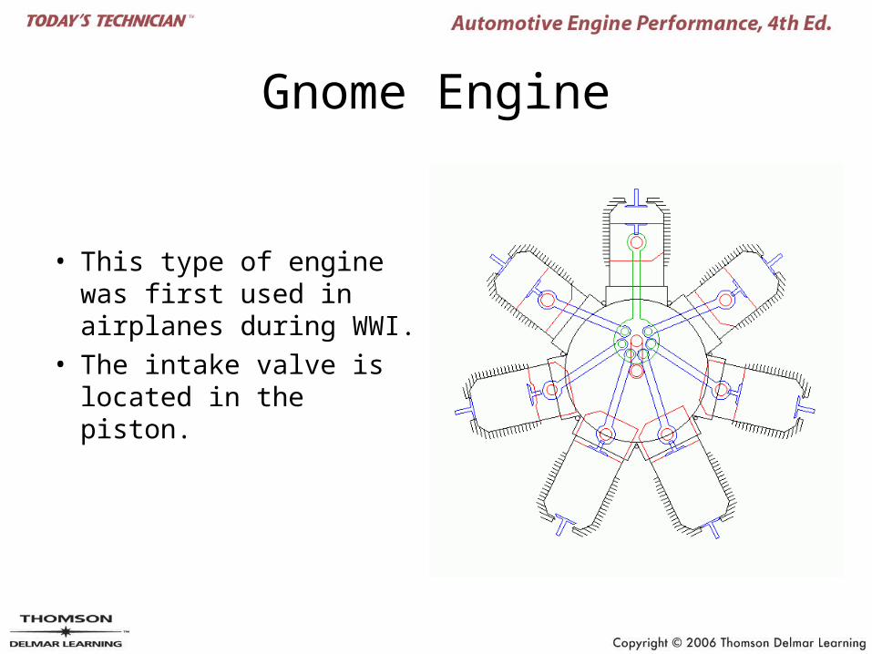
Gnome Engine
• This type of engine was first used in airplanes during WWI.
• The intake valve is located in the piston.
Gasoline Engine Systems
• Air-fuel system
• Ignition system
• Lubrication system
• Cooling system
• Exhaust system
• Emission control system
Engine Lubrication
• Engine oil– Service rating and viscosity grade
• American Petroleum Institute (API)• Society of Automotive Engineers (SAE)
• Friction modifiers
• Antifoaming agents
• Corrosion and rust inhibitors
• Extreme pressure resistance
Engine Lubrication
• Detergents and dispersants
• Oxidation inhibitors
• Viscosity
• Synthetic oils
• Recycled oils
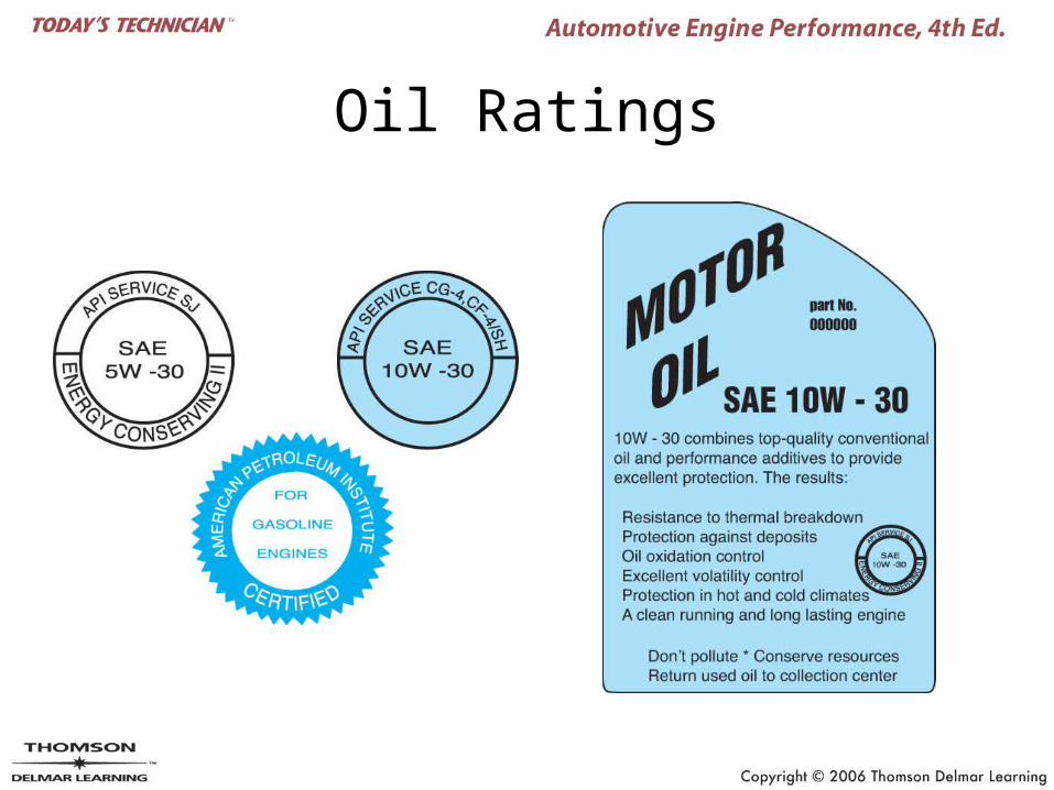
Oil Ratings
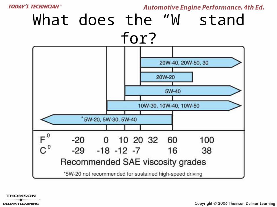
What does the “W” stand for?
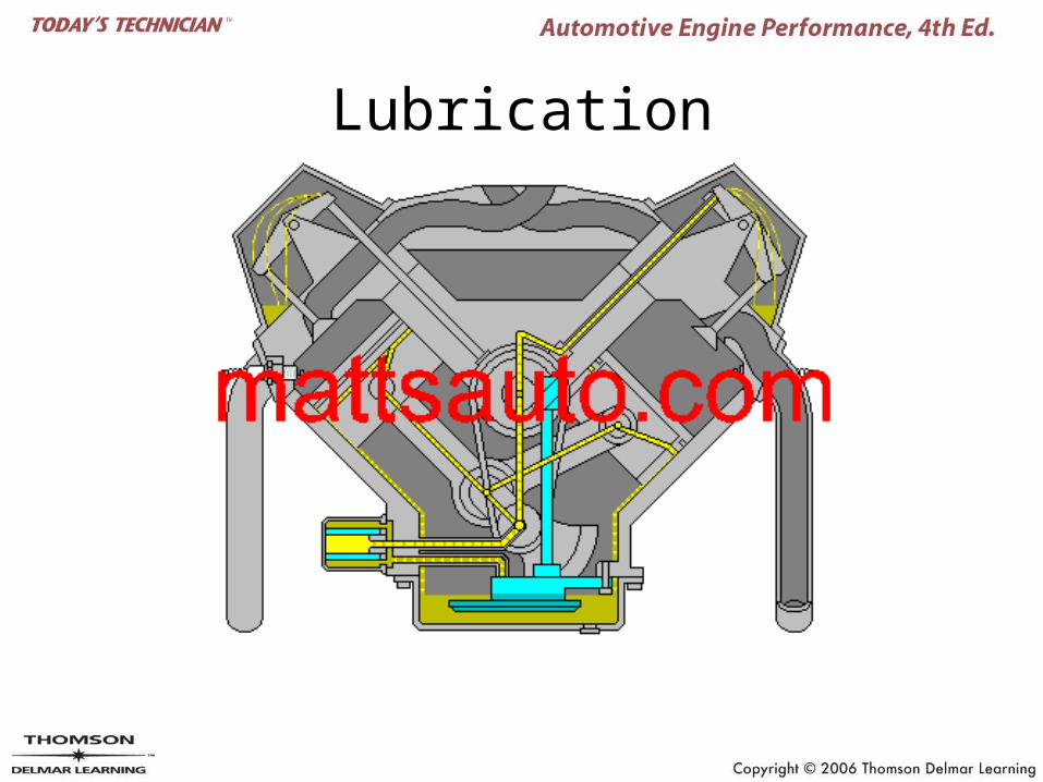
Lubrication
Oil Functions
Lubricating Systems
• Oil pump
• Oil pump pickup
• Oil pan or sump
• Pressure relief valve
• Oil filter
• Engine oil passages or galleries
• Engine bearings
Lubricating Systems
• Crankcase ventilation
• Oil pressure indicator
• Oil seals and gaskets
• Dipstick
• Oil coolers
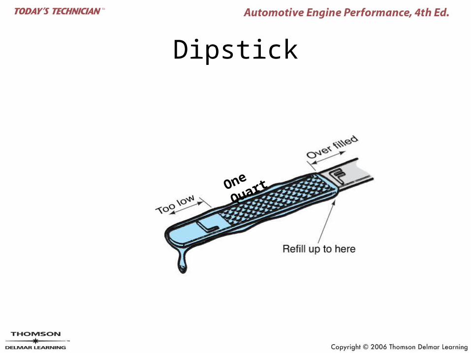
Dipstick
One Quart
Lubrication System
Oil Pump Operation
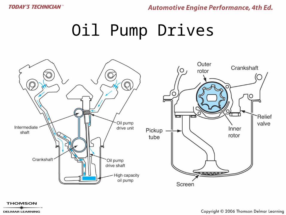
Oil Pump Drives
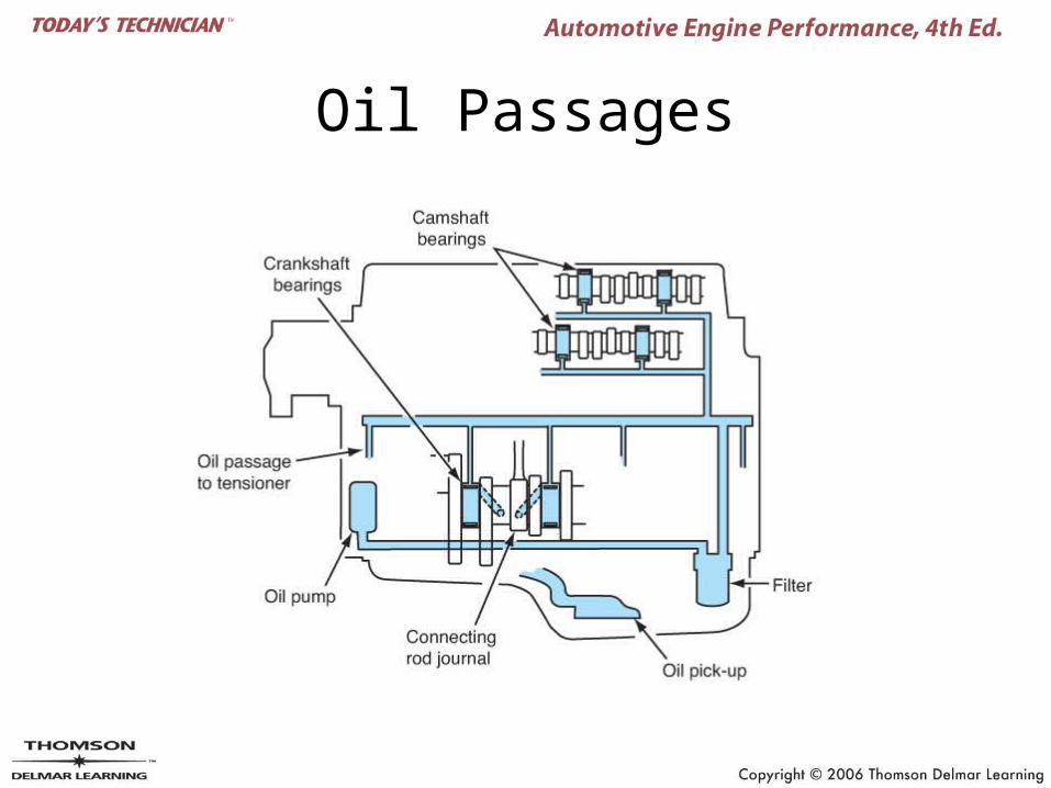
Oil Passages
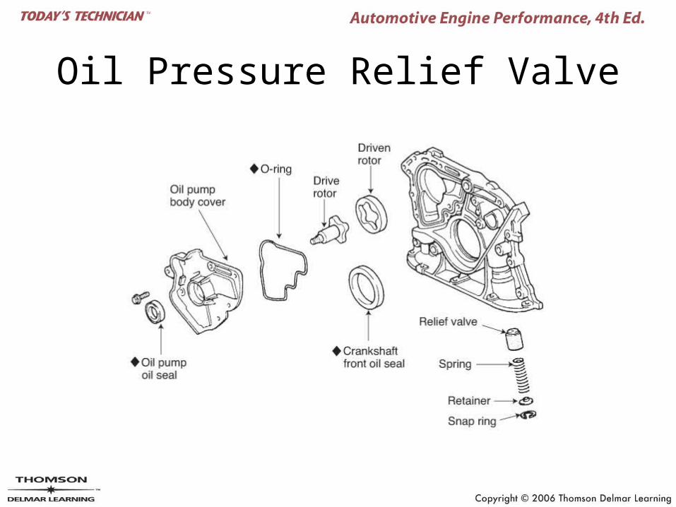
Oil Pressure Relief Valve
Cooling Systems
• Liquid-cooled system
• Coolant
• Water pump
• Radiator
• Radiator pressure cap
• Water outlet
• Hoses
• Thermostat
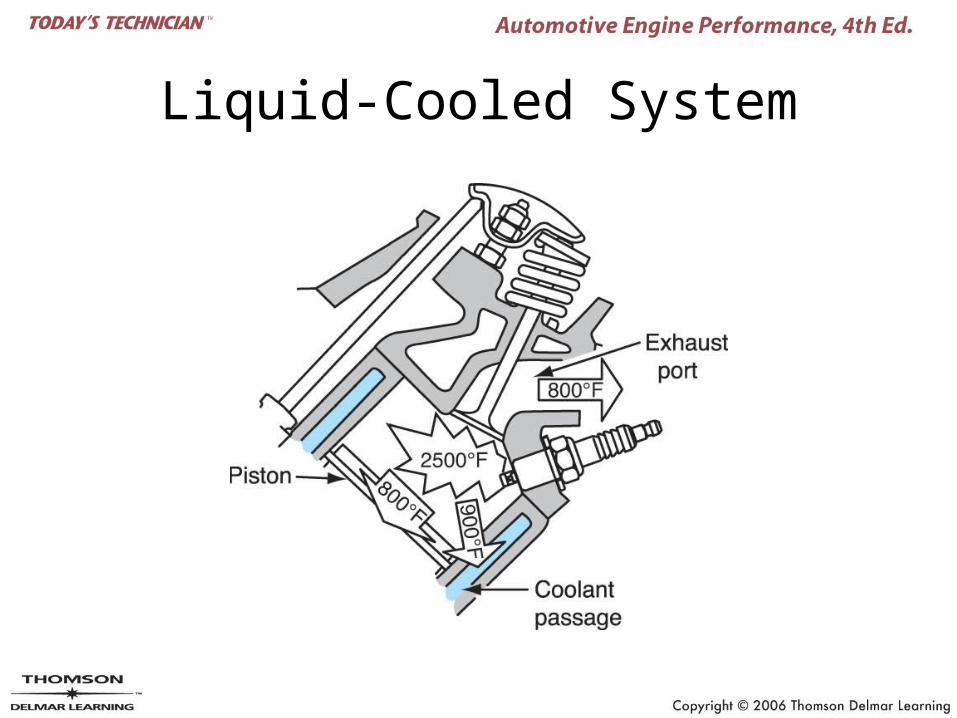
Liquid-Cooled System
Cooling Systems
• Belt drives
• Fans and fan clutches
• Water jackets– Series flow– Parallel flow– Series-parallel flow– Reverse flow
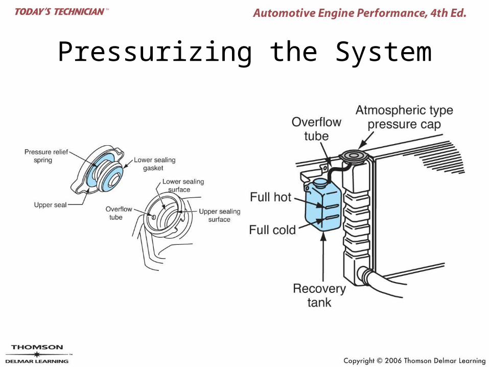
Pressurizing the System
Radiator Cap
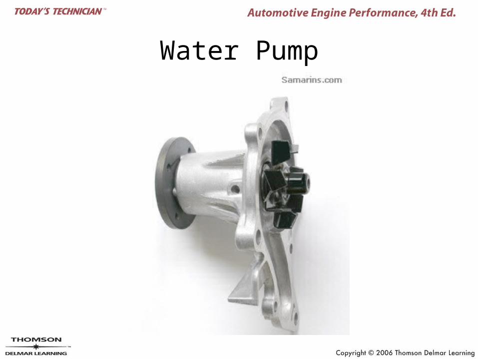
Water Pump
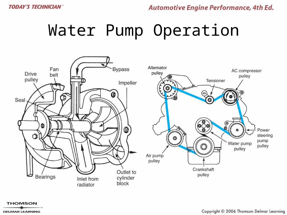
Water Pump Operation
Water Pump
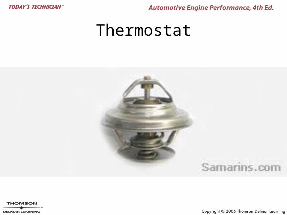
Thermostat
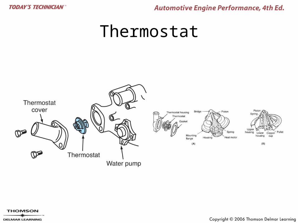
Thermostat
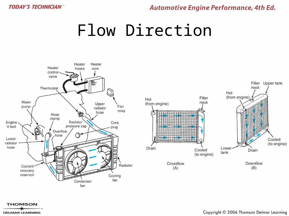
Flow Direction
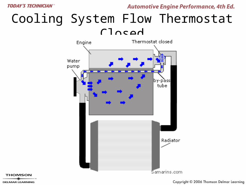
Cooling System Flow Thermostat Closed
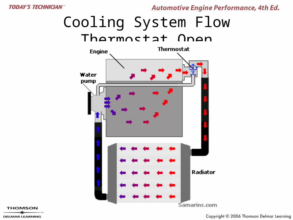
Cooling System Flow Thermostat Open
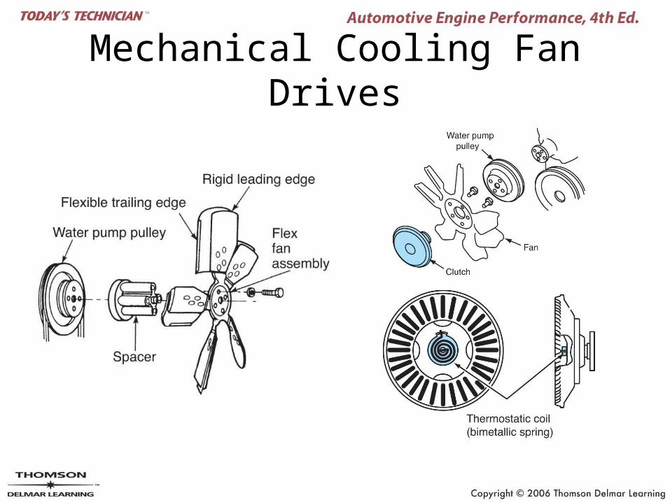
Mechanical Cooling Fan Drives
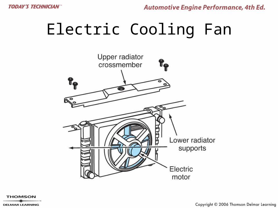
Electric Cooling Fan
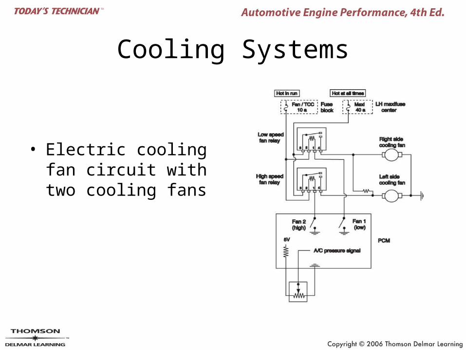
Cooling Systems
• Electric cooling fan circuit with two cooling fans
General Diagnostic Procedure
• The key to diagnostics is to know:– What test to conduct– When to conduct a test
• To know this you must understand:– The system – The test
Engine Leak Diagnosis
• Fuel leak diagnosis
• Engine oil leak diagnosis– Dye can be used with a black-light for hard-to-
find leaks.
• Engine coolant leak diagnosis– Use a cooling system pressure tester to
pressurize the system.
Engine Noise Diagnosis (1 of 2)
• Main bearing noise• Connecting rod bearing noise
– Will be greater under load– Disconnect sparkplug wire from each cylinder and
listen for noise to diminish• Piston slap
– Usually heard at when engine is first started (cold) and diminishes as engine warms up.
• Piston pin noise• Piston ring noise• Ring ridge noise
Engine Noise Diagnosis (2 of 2)
• Valvetrain noise and camshaft noise– These noises will be half the frequency of
engine speed
• Combustion noises– Spark knock– Check ignition timing and fuel quality
• Flywheel and vibration damper noise
Engine Exhaust Diagnosis
• Exhaust smoke– Blue smoke indicates excessive oil
consumption.– Black smoke indicates a rich air-fuel mixture.– Light gray/white smoke indicates coolant leak.
• Exhaust noise– Minor leaks can sound like a ticking noise
Diagnosis of Oil consumption
• Excessive oil consumption may be caused by:– External leaks– Combustion chamber leaks
• Usually rings
– Plugged PCV system
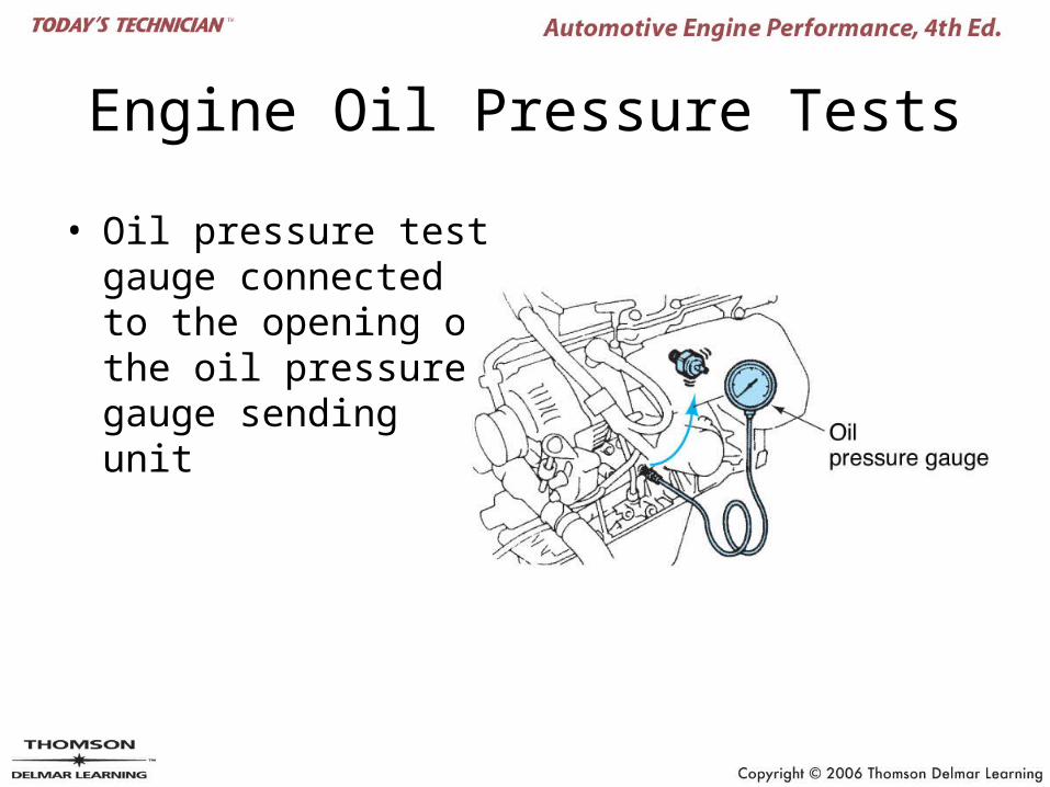
Engine Oil Pressure Tests
• Oil pressure test gauge connected to the opening of the oil pressure gauge sending unit
Engine Temperature Tests
• Thermostat
• Belts and hoses
• Radiator
• Radiator shroud
• Radiator cap
• Cooling system pressure test
• Antifreeze protection
• Cooling fan
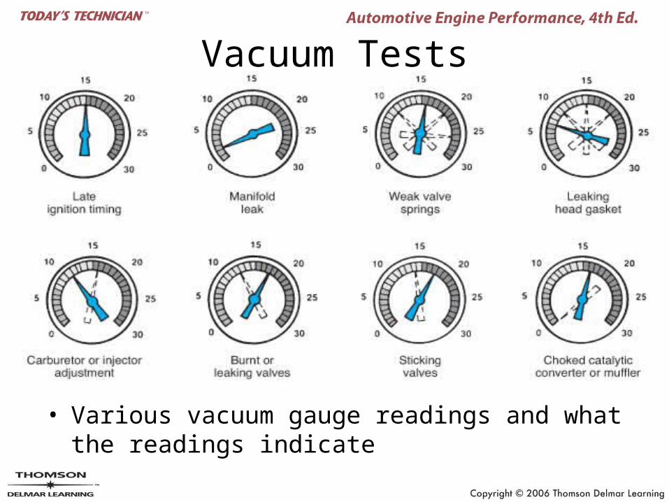
Vacuum Tests
• Various vacuum gauge readings and what the readings indicate
Exhaust Gas Analyzer (1 of 3)
• Looks at the results of the combustion process
• Measures– Hydrocarbons (HC)– Carbon monoxide (CO)
– Carbon dioxide (CO2)
– Oxygen (O2)
– Oxides of nitrogen (NOx)
Exhaust Gas Analyzer (2 of 3)
• Quick tests using the exhaust analyzer– Engine manifold vacuum leaks– Leaking injectors– Fuel combustion efficiency test– Contaminated motor oil test– PCV test– Air injection reaction (AIR) test
Exhaust Gas Analyzer (3 of 3)
– General emissions test– Fuel enrichment test– Combustion chamber leaks– Locating a fuel leak– Excessive valve guide wear
Engine Power Balance Test
• Checks the efficiency of individual cylinders
• May be used to identify the problem cylinder
• Disables each cylinder individually
• The cylinder that drops the least RPM is contributing the least amount of power.
Compression Tests
• Compression test– Checks the sealing ability of
• The rings• The valves• The combustion chamber
• Wet compression test– Determines if the leak is from the rings or valves
• Running compression test– Tests the cylinder’s volumetric efficiency
Cylinder Leakage Test (1 of 2)
• Determines where the leak is– The rings
• Air will leak out oil cap
– The valves• Air will leak through the throttle body if the intake
valve is not sealing• Air will leak through the tailpipe if the exhaust valve
is leaking
– The combustion chamber• Usually a bad head gasket• Could be a cracked cylinder head or block
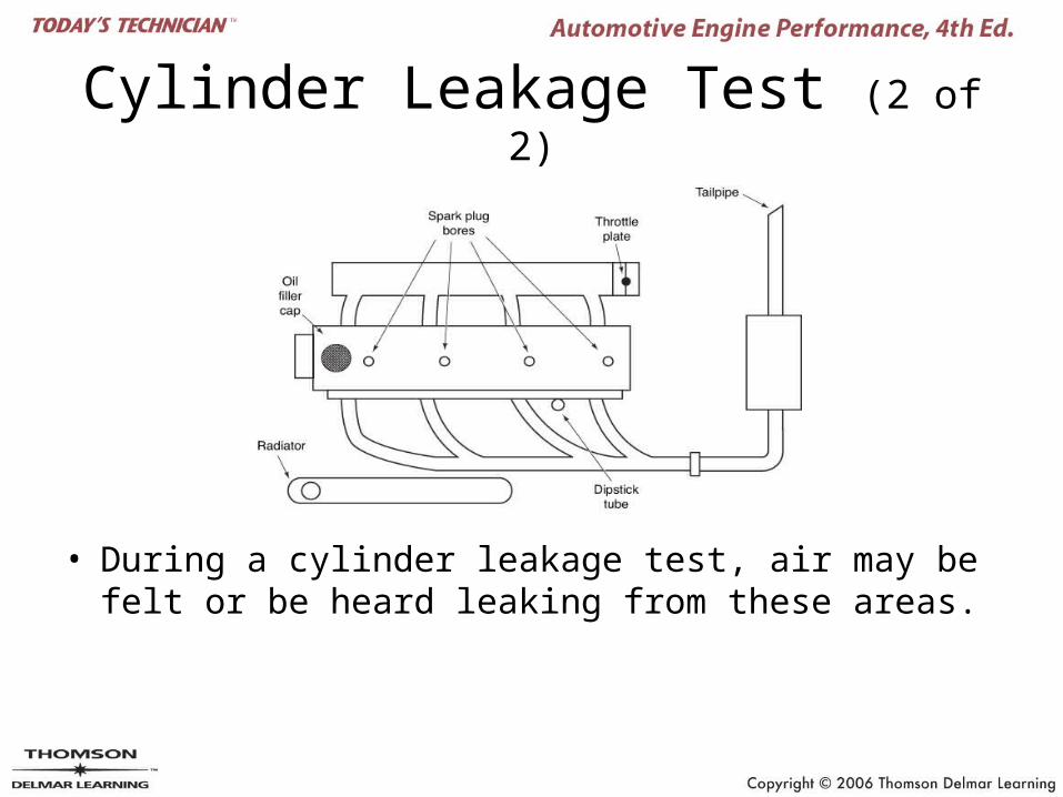
Cylinder Leakage Test (2 of 2)
• During a cylinder leakage test, air may be felt or be heard leaking from these areas.
Valve Timing Checks
• Checks to determine if the camshaft is in time with the crankshaft– The timing chain or belt may have jumped a
tooth due to excessive wear
Valve Adjustment (1 of 2)
• Required as maintenance on engines that use mechanical valve lifters
• Not required as maintenance on engines that use hydraulic lifters
• Should be done on any engine if the valve train components are worn or have been improperly serviced
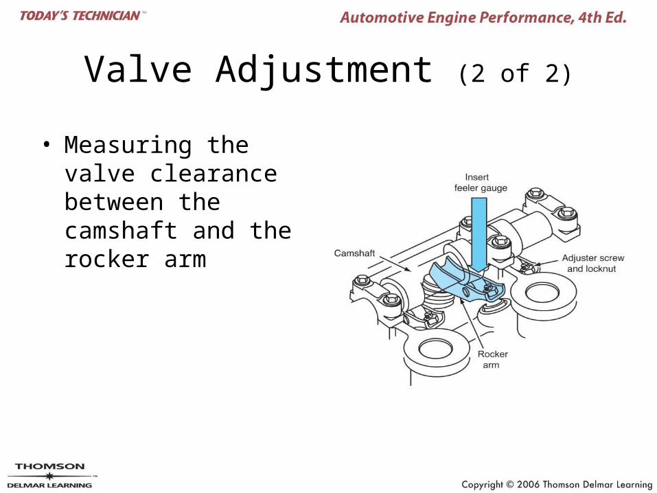
Valve Adjustment (2 of 2)
• Measuring the valve clearance between the camshaft and the rocker arm