Embed Size (px)
Citation preview

Foreword
Welcome to the growing family of new NISSANowners. This vehicle is delivered to you withconfidence. It was produced using the latesttechniques and strict quality control.
This manual was prepared to help you under-stand the operation and maintenance of yourvehicle so that you may enjoy many miles ofdriving pleasure. Please read through thismanual before operating your vehicle.
A separate Warranty Information Bookletexplains details about the warranties cov-ering your vehicle. The NISSAN Serviceand Maintenance Guide explains detailsabout maintaining and servicing your ve-hicle. Additionally, a separate CustomerCare/Lemon Law Booklet (U.S. only) willexplain how to resolve any concerns youmay have with your vehicle, as well asclarify your rights under your state’s lemonlaw.
Your NISSAN dealer knows your vehicle best.When you require any service or have anyquestions, we will be glad to assist you with theextensive resources available for you.
READ FIRST — THEN DRIVESAFELYBefore driving your vehicle please readyour Owner’s Manual carefully. This willensure familiarity with controls and main-
tenance requirements, assisting you in thesafe operation of your vehicle.
WARNING
IMPORTANT SAFETY INFORMA-TIONREMINDERS FOR SAFETY!Follow these important driving rules tohelp ensure a safe and comfortable tripfor you and your passengers!
� Never drive under the influence ofalcohol or drugs.
� Always observe posted speed limitsand never drive too fast for condi-tions.
� Always use the seat belts. Refer to“Child safety” and “Child restraints”in the “Safety — seats, seat belts andsupplemental restraint system” sec-tion for precautions regarding chil-dren.
� Always provide information about theproper use of vehicle safety featuresto all occupants of the vehicle.
� Always review this Owner’s Manualfor important safety information.
MODIFICATION OF YOUR VEHICLEThis vehicle should not be modified. Modi-fication could affect its performance,safety or durability, and may even violategovernmental regulations. In addition,damage or performance problems result-ing from modification may not be coveredunder NISSAN warranties.
WHEN READING THE MANUALThis manual includes information for alloptions available on this model. There-fore, you may find some information thatdoes not apply to your vehicle.
All information, specifications and illustrations inthis manual are those in effect at the time ofprinting. NISSAN reserves the right to changespecifications or design at any time withoutnotice.
� 04.8.3/Z50-D/V5.0 �

IMPORTANT INFORMATIONABOUT THIS MANUALYou will see various symbols in this manual.They are used in the following ways:
WARNING
This is used to indicate the presence of ahazard that could cause death or seriouspersonal injury. To avoid or reduce therisk, the procedures must be followedprecisely.
CAUTION
This is used to indicate the presence of ahazard that could cause minor or moder-ate personal injury or damage to yourvehicle. To avoid or reduce the risk, theprocedures must be followed carefully.
If you see this symbol, it means Do not do thisor Do not let this happen.
If you see a symbol similar to these in anillustration, it means the arrow points to the frontof the vehicle.
Arrows in an illustration that are similar to theseindicate movement or action.
Arrows in an illustration that are similar to thesecall attention to an item in the illustration.
CALIFORNIA PROPOSITION 65WARNING
WARNING
Engine exhaust, some of its constituents,and certain vehicle components containor emit chemicals known to the State ofCalifornia to cause cancer and birth de-fects or other reproductive harm. In ad-dition, certain fluids contained in ve-hicles and certain products of com-ponent wear contain or emit chemicalsknown to the State of California to causecancer and birth defects or other repro-ductive harm.
© 2004 NISSAN MOTOR CO., LTD.TOKYO, JAPAN
All rights reserved. No part of this Owner’s Manual may bereproduced or stored in a retrieval system, or transmittedin any form, or by any means, electronic, mechanical,photocopying, recording or otherwise, without the priorwritten permission of Nissan Motor Co., Ltd.
SIC0697
� 04.8.3/Z50-D/V5.0 �
Welcome To The World Of NISSAN
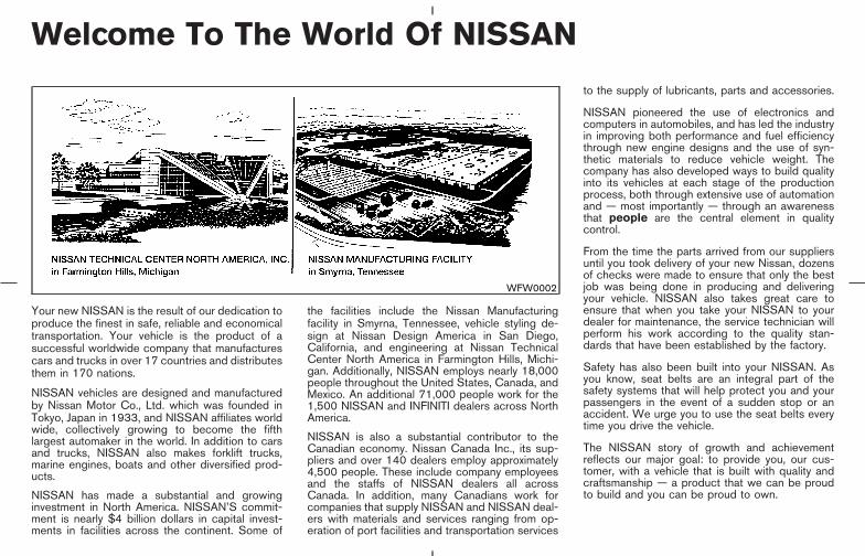
Your new NISSAN is the result of our dedication toproduce the finest in safe, reliable and economicaltransportation. Your vehicle is the product of asuccessful worldwide company that manufacturescars and trucks in over 17 countries and distributesthem in 170 nations.
NISSAN vehicles are designed and manufacturedby Nissan Motor Co., Ltd. which was founded inTokyo, Japan in 1933, and NISSAN affiliates worldwide, collectively growing to become the fifthlargest automaker in the world. In addition to carsand trucks, NISSAN also makes forklift trucks,marine engines, boats and other diversified prod-ucts.
NISSAN has made a substantial and growinginvestment in North America. NISSAN’S commit-ment is nearly $4 billion dollars in capital invest-ments in facilities across the continent. Some of
the facilities include the Nissan Manufacturingfacility in Smyrna, Tennessee, vehicle styling de-sign at Nissan Design America in San Diego,California, and engineering at Nissan TechnicalCenter North America in Farmington Hills, Michi-gan. Additionally, NISSAN employs nearly 18,000people throughout the United States, Canada, andMexico. An additional 71,000 people work for the1,500 NISSAN and INFINITI dealers across NorthAmerica.
NISSAN is also a substantial contributor to theCanadian economy. Nissan Canada Inc., its sup-pliers and over 140 dealers employ approximately4,500 people. These include company employeesand the staffs of NISSAN dealers all acrossCanada. In addition, many Canadians work forcompanies that supply NISSAN and NISSAN deal-ers with materials and services ranging from op-eration of port facilities and transportation services
to the supply of lubricants, parts and accessories.
NISSAN pioneered the use of electronics andcomputers in automobiles, and has led the industryin improving both performance and fuel efficiencythrough new engine designs and the use of syn-thetic materials to reduce vehicle weight. Thecompany has also developed ways to build qualityinto its vehicles at each stage of the productionprocess, both through extensive use of automationand — most importantly — through an awarenessthat people are the central element in qualitycontrol.
From the time the parts arrived from our suppliersuntil you took delivery of your new Nissan, dozensof checks were made to ensure that only the bestjob was being done in producing and deliveringyour vehicle. NISSAN also takes great care toensure that when you take your NISSAN to yourdealer for maintenance, the service technician willperform his work according to the quality stan-dards that have been established by the factory.
Safety has also been built into your NISSAN. Asyou know, seat belts are an integral part of thesafety systems that will help protect you and yourpassengers in the event of a sudden stop or anaccident. We urge you to use the seat belts everytime you drive the vehicle.
The NISSAN story of growth and achievementreflects our major goal: to provide you, our cus-tomer, with a vehicle that is built with quality andcraftsmanship — a product that we can be proudto build and you can be proud to own.
WFW0002
� 04.8.3/Z50-D/V5.0 �

NISSAN CUSTOMER CARE PROGRAM
NISSAN CARES ...
Both NISSAN and your NISSAN dealer are dedicated to serving all your automotive needs. Your satisfaction with your vehicle and your NISSAN dealerare our primary concerns. Your NISSAN dealer is always available to assist you with all your automobile sales and service needs.
However, if there is something that yourNISSAN dealer cannot assist you with or youwould like to provide NISSAN directly withcomments or questions, please contact our(NISSAN’s) Consumer Affairs Department us-ing our toll-free number:
For U.S. customers1-800-NISSAN-1(1-800-647-7261)
For Canadian customers1-800-387-0122
The Consumer Affairs Department will ask forthe following information:— Your name, address, and telephone
number— Vehicle identification number (on dash panel)— Date of purchase— Current odometer reading— Your NISSAN dealer’s name— Your comments or questionsOR
You can write to NISSAN with the informationon the left at:
For U.S. customersNissan North America, Inc.Consumer Affairs DepartmentP.O. Box 191Gardena, California 90248-0191
For Canadian customersNissan Canada Inc.5290 Orbitor DriveMississauga, Ontario L4W 4Z5
We appreciate your interest in NISSAN and thank you for buying a quality NISSAN vehicle.
� 04.8.3/Z50-D/V5.0 �
Table ofContents
Illustrated table of contents
Safety — seats, seat belts and supplementalrestraint system
Instruments and controls
Pre-driving checks and adjustments
Display screen, heater, air conditioner and audiosystems
Starting and driving
In case of emergency
Appearance and care
Maintenance and do-it-yourself
Technical and consumer information
Index
� 04.8.3/Z50-D/V5.0 �
0 Illustrated table of contents
Exterior front ............................................................................ 0-2Exterior rear ............................................................................. 0-3Instrument panel..................................................................... 0-4Meters and gauges ............................................................... 0-6Engine compartment check locations .............................. 0-7
� 04.8.3/Z50-D/V5.0 �

1. Hood (Page 3-24)
2. Windshield wiper and washer switch(P.2-20)/Wiper replacement (P.8-18)
3. Headlight and turn signal switch (P.2-22)/Bulb replacement (P.8-27)
4. Interior light (P.2-39)
5. Sunroof* (P.2-37)
6. Power windows (P.2-35)
7. Towing hook (P.6-12)
8. Fog light switch* (P.2-26)/Daytime running light (for Canada) (P.2-25)
9. Tires— Wheel and tires (P.8-29, P.9-9)— Flat tire (P.6-2)
10. Mirrors (P.3-30)
11. Doors— Keys (P.3-2)— Door locks (P.3-3)— Remote keyless entry system (P.3-5)
(P.3-20)— Intelligent Key* (P.3-9)
*: if so equipped
SSI0008
EXTERIOR FRONT
0-2 Illustrated table of contents
� 04.8.3/Z50-D/V5.0 �
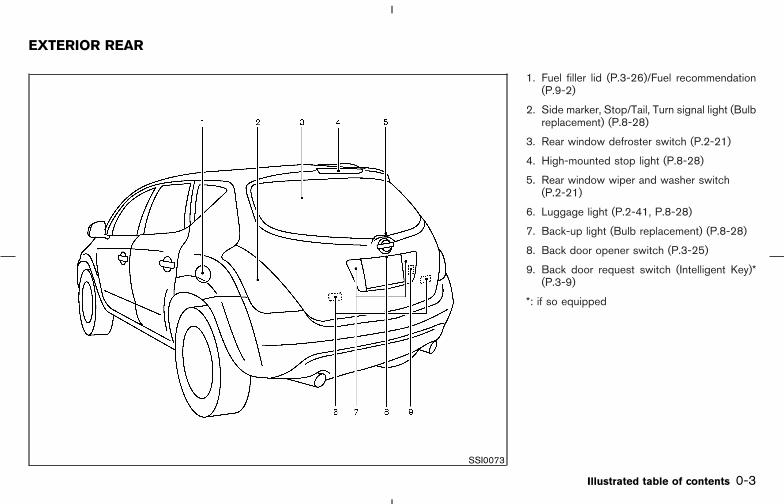
1. Fuel filler lid (P.3-26)/Fuel recommendation(P.9-2)
2. Side marker, Stop/Tail, Turn signal light (Bulbreplacement) (P.8-28)
3. Rear window defroster switch (P.2-21)
4. High-mounted stop light (P.8-28)
5. Rear window wiper and washer switch(P.2-21)
6. Luggage light (P.2-41, P.8-28)
7. Back-up light (Bulb replacement) (P.8-28)
8. Back door opener switch (P.3-25)
9. Back door request switch (Intelligent Key)*(P.3-9)
*: if so equipped
SSI0073
EXTERIOR REAR
Illustrated table of contents 0-3
� 04.8.3/Z50-D/V5.0 �
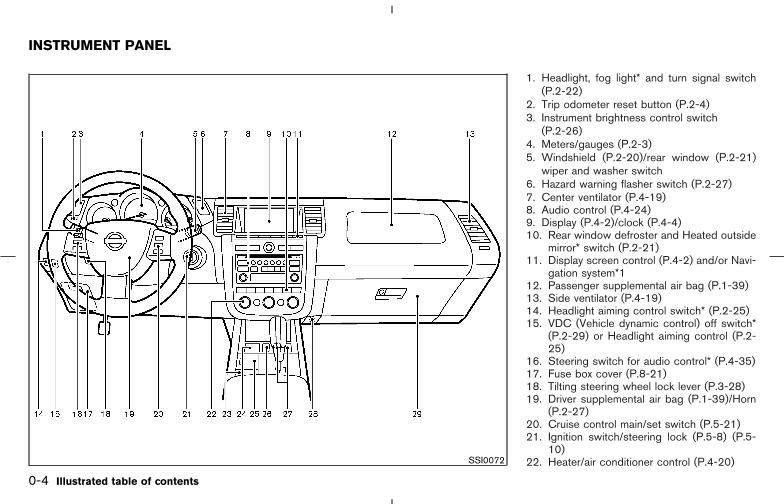
1. Headlight, fog light* and turn signal switch(P.2-22)
2. Trip odometer reset button (P.2-4)3. Instrument brightness control switch
(P.2-26)4. Meters/gauges (P.2-3)5. Windshield (P.2-20)/rear window (P.2-21)
wiper and washer switch6. Hazard warning flasher switch (P.2-27)7. Center ventilator (P.4-19)8. Audio control (P.4-24)9. Display (P.4-2)/clock (P.4-4)10. Rear window defroster and Heated outside
mirror* switch (P.2-21)11. Display screen control (P.4-2) and/or Navi-
gation system*112. Passenger supplemental air bag (P.1-39)13. Side ventilator (P.4-19)14. Headlight aiming control switch* (P.2-25)15. VDC (Vehicle dynamic control) off switch*
(P.2-29) or Headlight aiming control (P.2-25)
16. Steering switch for audio control* (P.4-35)17. Fuse box cover (P.8-21)18. Tilting steering wheel lock lever (P.3-28)19. Driver supplemental air bag (P.1-39)/Horn
(P.2-27)20. Cruise control main/set switch (P.5-21)21. Ignition switch/steering lock (P.5-8) (P.5-
10)22. Heater/air conditioner control (P.4-20)SSI0072
INSTRUMENT PANEL
0-4 Illustrated table of contents
� 04.8.3/Z50-D/V5.0 �

23. Coin box (P.2-30)24. Outside mirror remote control (P.3-32)25. Cellular phone holder (P.2-31)26. AWD lock switch (AWD models) (P.5-24)27. Heated seat switch* (P.2-28)28. Power outlet cover* (P.2-29)29. Glove box (P.2-32)
*: if so equipped
*1: Refer to the separate Navigation SystemOwner’s Manual.
Illustrated table of contents 0-5
� 04.8.3/Z50-D/V5.0 �

1. Tachometer (P.2-4)
2. Turn signal indicator (P.2-26)/Hazard indica-tor (P.2-27)
3. Speedometer (P.2-4)
4. Engine coolant temperature gauge (P.2-5)
5. Fuel gauge (P.2-5)
6. Reset button for trip odometer (P.2-4)
7. Warning/Indicator lights (P.2-9)
8. Odometer (Total/Twin trip) (P.2-4)
9. CVT shift position indicator (P.5-12)
SIC2039
METERS AND GAUGES
0-6 Illustrated table of contents
� 04.8.3/Z50-D/V5.0 �
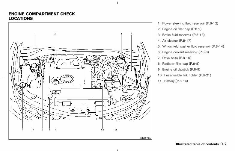
1. Power steering fluid reservoir (P.8-12)
2. Engine oil filler cap (P.8-9)
3. Brake fluid reservoir (P.8-13)
4. Air cleaner (P.8-17)
5. Windshield washer fluid reservoir (P.8-14)
6. Engine coolant reservoir (P.8-8)
7. Drive belts (P.8-16)
8. Radiator filler cap (P.8-8)
9. Engine oil dipstick (P.8-9)
10. Fuse/fusible link holder (P.8-21)
11. Battery (P.8-14)
SDI1760
ENGINE COMPARTMENT CHECKLOCATIONS
Illustrated table of contents 0-7
� 04.8.3/Z50-D/V5.0 �

MEMO
0-8 Illustrated table of contents
� 04.8.3/Z50-D/V5.0 �

1 Safety — seats, seat belts and supplemen-tal restraint system
Seats ......................................................................................... 1-2Front manual seat adjustment — passenger side ... 1-3Front power seat adjustment ........................................ 1-4Rear seat adjustment ...................................................... 1-5Head restraint adjustment.............................................. 1-7Active head restraint (front seats) ............................... 1-8Armrest ............................................................................... 1-9
Seat belts................................................................................. 1-9Precautions on seat belt usage.................................... 1-9Child safety ..................................................................... 1-12Pregnant women............................................................ 1-13Injured persons............................................................... 1-13Three-point type seat belt with retractor................. 1-13Rear center seat belt .................................................... 1-17Seat belt extenders ....................................................... 1-20Seat belt maintenance ................................................. 1-20
Child restraints ..................................................................... 1-21
Precautions on child restraints................................... 1-21Child restraint installation on rear seat outboard orcenter positions.............................................................. 1-22LATCH (Lower Anchors and Tethers for CHildren)system .............................................................................. 1-27Top tether strap child restraint................................... 1-29Installation on front passenger seat.......................... 1-31
Booster seats ....................................................................... 1-34Precautions on booster seats .................................... 1-34Booster seat installation on rear seat outboard orcenter positions.............................................................. 1-37Booster seat installation on front passengerseat.................................................................................... 1-38
Supplemental restraint system......................................... 1-39Precautions on supplemental restraint system ...... 1-39Supplemental air bag warning labels ....................... 1-49Supplemental air bag warning light .......................... 1-50
� 04.8.3/Z50-D/V5.0 �

WARNING
� Do not ride in a moving vehicle whenthe seatback is reclined. This can bedangerous. The shoulder belt will notbe against your body. In an accident,you could be thrown into it and re-ceive neck or other serious injuries.You could also slide under the lapbelt and receive serious internalinjuries.
� For the most effective protectionwhen the vehicle is in motion, theseat should be upright. Always sitwell back in the seat and adjust theseat belt properly. See “Precautionson seat belt usage” later in this sec-tion.
SSS0133B
SEATS
1-2 Safety — seats, seat belts and supplemental restraint system
� 04.8.3/Z50-D/V5.0 �

FRONT MANUAL SEATADJUSTMENT — Passenger side
WARNING
After adjustment, gently rock in the seatto make sure it is securely locked.
Forward and backwardPull the lever up �1 while you slide the seatforward or backward to the desired position.Release the lever to lock the seat in position.
RecliningTo recline the seatback, pull the lever up �2 andlean back. To bring the seatback forward again,pull the lever and move your body forward. Theseatback moves forward.
The reclining feature allows adjustment of theseatback for occupants of different sizes foradded comfort and to help obtain proper seatbelt fit. (See “Precautions on seat belt usage”later in this section.) The seatback may also bereclined to allow occupants to rest when thevehicle is parked.
SSS0179A
Safety — seats, seat belts and supplemental restraint system 1-3
� 04.8.3/Z50-D/V5.0 �
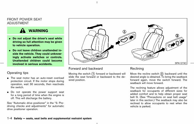
FRONT POWER SEATADJUSTMENT
WARNING
� Do not adjust the driver’s seat whiledriving so full attention may be givento vehicle operation.
� Do not leave children unattended in-side the vehicle. They could unknow-ingly activate switches or controls.Unattended children could becomeinvolved in serious accidents.
Operating tips� The seat motor has an auto-reset overload
protection circuit. If the motor stops duringoperation, wait 30 seconds, then reactivatethe switch.
� Do not operate the power support seatfor a long period of time when the engine isoff. This will discharge the battery.
See “Automatic drive positioner” in the “3. Pre-driving checks and adjustments” for automaticdrive positioner operation.
Forward and backwardMoving the switch �1 forward or backward willslide the seat forward or backward to the de-sired position.
RecliningMove the recline switch �2 backward until thedesired angle is obtained. To bring the seatbackforward again, move the switch forward. Theseatback will move forward.
The reclining feature allows adjustment of theseatback for occupants of different sizes foradded comfort and to help obtain proper seatbelt fit. (See “Precautions on seat belt usage”later in this section.) The seatback may also bereclined to allow occupants to rest when thevehicle is parked.
SPA1273C
1-4 Safety — seats, seat belts and supplemental restraint system
� 04.8.3/Z50-D/V5.0 �

Seat lifter (if so equipped for driver’sseat)1. Pull up or push down the switch �1 to adjust
the seat height.
2. Tilt up or down the switch �1 to adjust theseat angle.
Lumbar support (if so equipped fordriver’s seat)The lumbar support feature provides lower backsupport to the driver. Push each side of theswitch to adjust the seat lumbar area.
REAR SEAT ADJUSTMENT
Folding
1. Secure the seat belt at the belt hooks on theside wall. See “Seat belt hook” later in thissection.
2. Secure the center seat belt and tongues intothe retractor base. See “Stowing rear centerseat belt” later in this section.
3. Put the seat belt buckles into the seat cush-ion.See “Storing rear seat belt buckles” later inthis section.
SPA1275B SSS0280 SSS0420
Safety — seats, seat belts and supplemental restraint system 1-5
� 04.8.3/Z50-D/V5.0 �
4. Remove the head restraints. See “Head re-straint adjustment” later in this section.
5. After closing the tonneau sub cover (if soequipped) from each rear seatback, pull thestrap on the rear seat �A or pull the lever �Bbeside the cargo area and fold the seatback.
6. When returning the seatbacks, be sure toinstall the head restraints and attach the rearcenter seat belt connector.
WARNING
� Never allow anyone to ride in thecargo area or on the rear seat when itis in the fold-down position. Use ofthese areas by passengers withoutproper restraints could result in seri-ous injury in an accident or suddenstop.
� It is extremely dangerous to ride in acargo area inside of a vehicle. In acollision, people riding in these areasare more likely to be seriously in-jured or killed.
� Do not allow people to ride in anyarea of your vehicle that is not
equipped with seats and seat belts.Be sure everyone in your vehicle is ina seat and using a seat belt properly.
� Do not fold down the rear seats whenoccupants are in the rear seat area orany luggage is on the rear seats.
� Head restraints should be adjustedproperly as they may provide signifi-cant protection against injury in anaccident. Always replace and adjustthem properly if they have been re-moved for any reason.
� If the head restraints are removed forany reason, they should be securelystored to prevent them from causinginjury to passengers or damage tothe vehicle in case of sudden brakingor an accident.
� Properly secure all cargo to help pre-vent it from sliding or shifting. Do notplace cargo higher than the seat-backs. In a sudden stop or collision,unsecured cargo could cause per-sonal injury.
� When returning the seatbacks to theupright position, be certain they arecompletely secured in the latched po-sition. If they are not completely se-cured, passengers may be injured inan accident or sudden stop.
� When returning the seatbacks, besure to attach the rear center seatbelt connector.
� Do not unfasten the rear center seatbelt connector except when foldingdown the rear seat.
� Do not remove the head restraintsexcept when folding down the rearseat or using certain child restraints.
� When attaching the rear center seatbelt connector, be certain that theseatbacks are completely secured inthe latched position and the rear cen-ter seat belt connector is completelysecured.
� If the rear center seat belt connectorand the seatbacks are not secured inthe correct position, serious personalinjury may result in an accident orsudden stop.
1-6 Safety — seats, seat belts and supplemental restraint system
� 04.8.3/Z50-D/V5.0 �
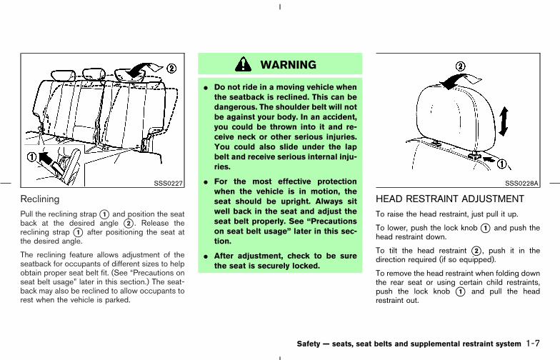
RecliningPull the reclining strap �1 and position the seatback at the desired angle �2 . Release thereclining strap �1 after positioning the seat atthe desired angle.
The reclining feature allows adjustment of theseatback for occupants of different sizes to helpobtain proper seat belt fit. (See “Precautions onseat belt usage” later in this section.) The seat-back may also be reclined to allow occupants torest when the vehicle is parked.
WARNING
� Do not ride in a moving vehicle whenthe seatback is reclined. This can bedangerous. The shoulder belt will notbe against your body. In an accident,you could be thrown into it and re-ceive neck or other serious injuries.You could also slide under the lapbelt and receive serious internal inju-ries.
� For the most effective protectionwhen the vehicle is in motion, theseat should be upright. Always sitwell back in the seat and adjust theseat belt properly. See “Precautionson seat belt usage” later in this sec-tion.
� After adjustment, check to be surethe seat is securely locked.
HEAD RESTRAINT ADJUSTMENTTo raise the head restraint, just pull it up.
To lower, push the lock knob �1 and push thehead restraint down.
To tilt the head restraint �2 , push it in thedirection required (if so equipped).
To remove the head restraint when folding downthe rear seat or using certain child restraints,push the lock knob �1 and pull the headrestraint out.
SSS0227 SSS0228A
Safety — seats, seat belts and supplemental restraint system 1-7
� 04.8.3/Z50-D/V5.0 �
WARNING
� Head restraints should be adjustedproperly as they may provide signifi-cant protection against injury in anaccident. Check the adjustment aftersomeone else uses the seat.
� Do not remove the head restraintsexcept when folding down the rearseat or using certain child restraints.Always replace and adjust themproperly if they have been removedfor any reason.
� If the head restraints are removed forany reason, they should be securelystored to prevent them from causinginjury to passengers or damage tothe vehicle in case of sudden brakingor an accident.
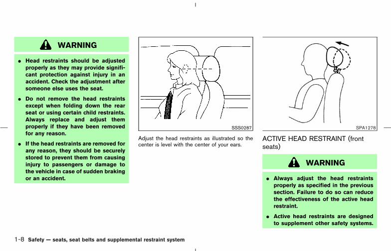
Adjust the head restraints as illustrated so thecenter is level with the center of your ears.
ACTIVE HEAD RESTRAINT (frontseats)
WARNING
� Always adjust the head restraintsproperly as specified in the previoussection. Failure to do so can reducethe effectiveness of the active headrestraint.
� Active head restraints are designedto supplement other safety systems.
SSS0287 SPA1278
1-8 Safety — seats, seat belts and supplemental restraint system
� 04.8.3/Z50-D/V5.0 �

Always wear seat belts. No systemcan prevent all injuries in any acci-dent.
� Do not attach anything to the headrestraint stalks. Doing so could im-pair active head restraint function.
The head restraint moves forward utilizing theforce that the seatback receives from the occu-pant in a rear-end collision. The movement of thehead restraint helps support the occupant’shead by reducing its backward movement andhelping absorb some of the forces that may leadto whiplash type injuries.
Active head restraints are effective for collisionsat low to medium speeds in which it is said thatwhiplash injury occurs most.
Active head restraints operate only in certainrear-end collisions. After the collision, the headrestraints return to their original positions.
Properly adjust the active head restraints asdescribed in the previous section.
ARMRESTPull the armrest forward until it is horizontal.
PRECAUTIONS ON SEAT BELTUSAGEIf you are wearing your seat belt properly ad-justed and you are sitting upright and well backin your seat, your chances of being injured orkilled in an accident and/or the severity of injurymay be greatly reduced. NISSAN strongly en-courages you and all of your passengers tobuckle up every time you drive, even if yourseating position includes a supplemental air bag.
Most states, provinces or territories re-quire that seat belts be worn at all timeswhen a vehicle is being driven.
SSS0229A
SEAT BELTS
Safety — seats, seat belts and supplemental restraint system 1-9
� 04.8.3/Z50-D/V5.0 �

WARNING
� Every person who drives or rides inthis vehicle should use a seat belt atall times. Children should be properlyrestrained in the rear seat and, ifappropriate, in a child restraint.
� The seat belt should be properly ad-justed to a snug fit. Failure to do somay reduce the effectiveness of theentire restraint system and increasethe chance or severity of injury in an
accident. Serious injury or death canoccur if the seat belt is not wornproperly.
� Always route the shoulder belt overyour shoulder and across your chest.Never run the belt behind your back,under your arm or across your neck.The belt should be away from yourface and neck, but not falling off yourshoulder.
� Position the lap belt as low and snugas possible AROUND THE HIPS, NOTTHE WAIST. A lap belt worn too highcould increase the risk of internalinjuries in an accident.
� Be sure the seat belt tongue is se-curely fastened to the proper buckle.
� Do not wear the seat belt inside outor twisted. Doing so may reduce itseffectiveness.
� Do not allow more than one personto use the same belt.
� Never carry more people in the ve-hicle than there are seat belts.
� If the seat belt warning light glowscontinuously while the ignition isturned ON with all doors closed andall seat belts fastened, it may indi-cate a malfunction in the system.Have the system checked by aNISSAN dealer.
� Once the pre-tensioner seat belt hasactivated, it cannot be reused andmust be replaced together with the
SSS0136A
1-10 Safety — seats, seat belts and supplemental restraint system
� 04.8.3/Z50-D/V5.0 �

retractor. See your NISSAN dealer.
� Removal and installation of the pre-tensioner seat belt system compo-nents should be done by a NISSANdealer.
� All seat belt assemblies, includingretractors and attaching hardware,should be inspected after any colli-sion by a NISSAN dealer. NISSANrecommends that all seat belt as-semblies in use during a collision bereplaced unless the collision was mi-nor and the belts show no damage
and continue to operate properly.Seat belt assemblies not in use dur-ing a collision should also be in-spected and replaced if either dam-age or improper operation is noted.
� All child restraints and attachinghardware should be inspected afterany collision. Always follow the re-straint manufacturer’s inspection in-structions and replacement recom-mendations. The child restraintsshould be replaced if they are dam-aged.
SSS0134A SSS0016
SSS0014
Safety — seats, seat belts and supplemental restraint system 1-11
� 04.8.3/Z50-D/V5.0 �

CHILD SAFETYChildren need adults to help protect them.They need to be properly restrained.
In addition to the general information in thismanual, child safety information is available frommany other sources, including doctors, teachers,government traffic safety offices, and communityorganizations. Every child is different, so be sureto learn the best way to transport your child.
There are three basic types of child restraintsystems:
� Rear facing child restraint
� Front facing child restraint
� Booster seat
The proper restraint depends on the child’s size.Generally, infants (up to about 1 year and lessthan 20 lb (9 kg)) should be placed in rear facingchild restraints. Front facing child restraints areavailable for children who outgrow rear facingchild restraints and are at least 1 year old.Booster seats are used to help position a vehiclelap/shoulder belt on a child who can no longeruse a front facing child restraint.
WARNING
Infants and children need special pro-tection. The vehicle’s seat belts may notfit them properly. The shoulder belt maycome too close to the face or neck. Thelap belt may not fit over their small hipbones. In an accident, an improperlyfitting seat belt could cause serious orfatal injury. Always use appropriatechild restraints.
All U.S. states and Canadian provinces or terri-tories require the use of approved child re-straints for infants and small children. (See“Child restraints” later in this section.)
Also, there are other types of child restraintsavailable for larger children for additional protec-tion.
NISSAN recommends that all pre-teensand children be restrained in the rear seat.According to accident statistics, childrenare safer when properly restrained in therear seat than in the front seat. This isespecially important because your vehiclehas a supplemental restraint system (airbag system) for the front passenger. See
“Supplemental restraint system” later inthis section.
InfantsInfants up to at least one year old should beplaced in a rear facing child restraint. NISSANrecommends that infants be placed in childrestraints that comply with Federal Motor Ve-hicle Safety Standards or Canadian Motor Ve-hicle Safety Standards. You should choose achild restraint which fits your vehicle and alwaysfollow the manufacturer’s instructions for instal-lation and use.
Small childrenChildren that are over one year old and weightbetween 20 lbs (9 kg) and 40 lbs (18 kg) can beplaced in a forward facing child restraint. Referto the manufacturer’s instructions for minimumand maximum weight and height recommenda-tions. NISSAN recommends that small childrenbe placed in child restraints that comply withFederal Motor Vehicle Safety Standards or Ca-nadian Motor Vehicle Safety Standards. Youshould choose a child restraint that fits yourvehicle and always follow the manufacturer’sinstructions for installation and use.
1-12 Safety — seats, seat belts and supplemental restraint system
� 04.8.3/Z50-D/V5.0 �
Larger childrenChildren who are too large for child restraintsshould be seated and restrained by the seatbelts which are provided. The seat belt may notfit properly if the child is less than 4 feet 9 inches(142.5 cm) tall and weighs between 40 lbs (18kg) and 80 lbs (36 kg). A booster seat should beused to obtain proper seat belt fit.
NISSAN recommends that a child be placed in acommercially available booster seat if the shoul-der belt in the child’s seating position fits closeto the face or neck or if the lap portion of the seatbelt goes across the abdomen. The booster seatshould raise the child so that the shoulder belt isproperly positioned across the top, middle por-tion of the shoulder and the lap belt is low on thehips. A booster seat can only be used in seatingpositions that have a three-point type seat belt.The booster seat should fit the vehicle seat andhave a label certifying that it complies withFederal Motor Vehicle Safety Standards or Ca-nadian Motor Vehicle Safety Standards. Oncethe child has grown so the shoulder belt is nolonger on or near the face and neck, use theshoulder belt without the booster seat.
WARNING
Never let a child stand or kneel on anyseat and do not allow a child in thecargo areas while the vehicle is moving.The child could be seriously injured orkilled in an accident or sudden stop.
PREGNANT WOMENNISSAN recommends that pregnant women useseat belts. The seat belt should be worn snug,and always position the lap belt as low aspossible around the hips, not the waist. Placethe shoulder belt over your shoulder and acrossyour chest. Never run the lap/shoulder belt overyour abdominal area. Contact your doctor forspecific recommendations.
INJURED PERSONSNISSAN recommends that injured persons useseat belts, depending on the injury. Check withyour doctor for specific recommendations.
THREE-POINT TYPE SEAT BELTWITH RETRACTOR
WARNING
� Every person who drives or rides inthis vehicle should use a seat belt atall times.
� Do not ride in a moving vehicle whenthe seatback is reclined. This can bedangerous. The shoulder belt will notbe against your body. In an accident,you could be thrown into it and re-ceive neck or other serious injuries.You could also slide under the lapbelt and receive serious internal inju-ries.
� For the most effective protectionwhen the vehicle is in motion, theseat should be upright. Always sitwell back in the seat and adjust theseat belt properly.
Safety — seats, seat belts and supplemental restraint system 1-13
� 04.8.3/Z50-D/V5.0 �
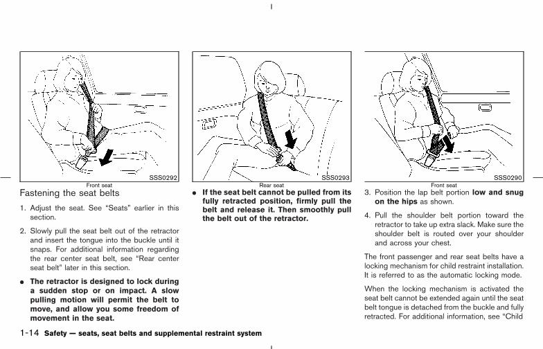
Fastening the seat belts
1. Adjust the seat. See “Seats” earlier in thissection.
2. Slowly pull the seat belt out of the retractorand insert the tongue into the buckle until itsnaps. For additional information regardingthe rear center seat belt, see “Rear centerseat belt” later in this section.
� The retractor is designed to lock duringa sudden stop or on impact. A slowpulling motion will permit the belt tomove, and allow you some freedom ofmovement in the seat.
� If the seat belt cannot be pulled from itsfully retracted position, firmly pull thebelt and release it. Then smoothly pullthe belt out of the retractor.
3. Position the lap belt portion low and snugon the hips as shown.
4. Pull the shoulder belt portion toward theretractor to take up extra slack. Make sure theshoulder belt is routed over your shoulderand across your chest.
The front passenger and rear seat belts have alocking mechanism for child restraint installation.It is referred to as the automatic locking mode.
When the locking mechanism is activated theseat belt cannot be extended again until the seatbelt tongue is detached from the buckle and fullyretracted. For additional information, see “Child
SSS0292Front seat
SSS0293Rear seat
SSS0290Front seat
1-14 Safety — seats, seat belts and supplemental restraint system
� 04.8.3/Z50-D/V5.0 �

restraints” later in this section.
The automatic locking mode should beused only for child restraint installation.During normal seat belt use by a passen-ger, the locking mode should not be acti-vated. If it is activated it may cause uncom-fortable seat belt tension.
WARNING
� When fastening the seat belts, becertain that the seatbacks are com-pletely secured in the latched posi-
tion. If they are not completely se-cured, passengers may be injured inan accident or sudden stop.
� When attaching the rear center seatbelt connector, be certain that theseatbacks are completely secured inthe latched position and the rear cen-ter seat belt connector is completelysecured.
� If the rear center seat belt connectorand the seatbacks are not secured inthe correct position, serious personalinjury may result in an accident orsudden stop. Unfastening the seat belts
To unfasten the belt, push the button on thebuckle. The seat belt will automatically retract.
Checking seat belt operation
Your seat belt retractors are designed to lockbelt movement using two separate methods:
� when the belt is pulled quickly from theretractor.
� when the vehicle slows down rapidly.
You can check their operation as follows:
� grasp the shoulder belt and pull quickly for-
SSS0291ARear seat
SSS0326
Safety — seats, seat belts and supplemental restraint system 1-15
� 04.8.3/Z50-D/V5.0 �
ward. The retractor should lock and restrictfurther belt movement.
If the retractor does not lock during this check orif you have any questions about belt operation,see a NISSAN dealer.
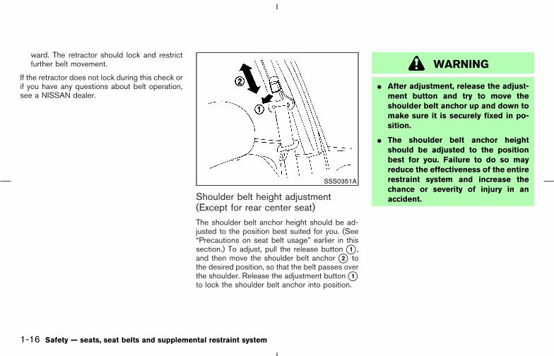
Shoulder belt height adjustment(Except for rear center seat)The shoulder belt anchor height should be ad-justed to the position best suited for you. (See“Precautions on seat belt usage” earlier in thissection.) To adjust, pull the release button �1 ,and then move the shoulder belt anchor �2 tothe desired position, so that the belt passes overthe shoulder. Release the adjustment button �1to lock the shoulder belt anchor into position.
WARNING
� After adjustment, release the adjust-ment button and try to move theshoulder belt anchor up and down tomake sure it is securely fixed in po-sition.
� The shoulder belt anchor heightshould be adjusted to the positionbest for you. Failure to do so mayreduce the effectiveness of the entirerestraint system and increase thechance or severity of injury in anaccident.
SSS0351A
1-16 Safety — seats, seat belts and supplemental restraint system
� 04.8.3/Z50-D/V5.0 �

Seat belt hookWhen folding down the rear seat, hook the rearseat belt at the belt hook.
REAR CENTER SEAT BELTThe rear center seat belt has a connector tongue�1 and a seat belt tongue �2 . Both the con-nector tongue and the seat belt tongue must besecurely latched for proper seat belt operation.
The connector tongue �1 should always beconnected except when folding down the rearseat.
WARNING
� Always fasten the connector tongueand the seat belt in the order shown.
� Always make sure both the connec-tor tongue and the seat belt tongueare secured when using the seat belt.Do not use it with only the seat belttongue attached. This could result inserious personal injury in case of anaccident or a sudden stop.
SSS0231 SSS0391 SSS0241
Safety — seats, seat belts and supplemental restraint system 1-17
� 04.8.3/Z50-D/V5.0 �
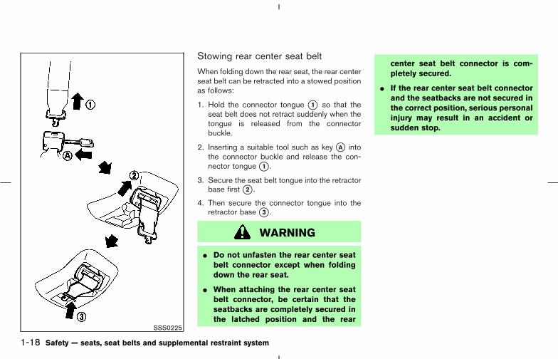
Stowing rear center seat belt
When folding down the rear seat, the rear centerseat belt can be retracted into a stowed positionas follows:
1. Hold the connector tongue �1 so that theseat belt does not retract suddenly when thetongue is released from the connectorbuckle.
2. Inserting a suitable tool such as key �A intothe connector buckle and release the con-nector tongue �1 .
3. Secure the seat belt tongue into the retractorbase first �2 .
4. Then secure the connector tongue into theretractor base �3 .
WARNING
� Do not unfasten the rear center seatbelt connector except when foldingdown the rear seat.
� When attaching the rear center seatbelt connector, be certain that theseatbacks are completely secured inthe latched position and the rear
center seat belt connector is com-pletely secured.
� If the rear center seat belt connectorand the seatbacks are not secured inthe correct position, serious personalinjury may result in an accident orsudden stop.
SSS0225
1-18 Safety — seats, seat belts and supplemental restraint system
� 04.8.3/Z50-D/V5.0 �
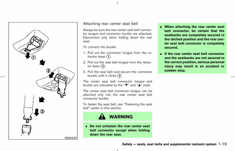
Attaching rear center seat beltAlways be sure the rear center seat belt connec-tor tongue and connector buckle are attached.Disconnect only when folding down the rearseat.
To connect the buckle:
1. Pull out the connector tongue from the re-tractor base �1 .
2. Pull out the seat belt tongue from the retrac-tor base �2 .
3. Pull the seat belt and secure the connectorbuckle until it clicks �3 .
The center seat belt connector tongue andbuckle are indicated by the “�” and “�” mark.
The center seat belt connector tongue can beattached only into the rear center seat beltconnector buckle.
To fasten the seat belt, see “Fastening the seatbelt” earlier in this section.
WARNING
� Do not unfasten the rear center seatbelt connector except when foldingdown the rear seat.
� When attaching the rear center seatbelt connector, be certain that theseatbacks are completely secured inthe latched position and the rear cen-ter seat belt connector is completelysecured.
� If the rear center seat belt connectorand the seatbacks are not secured inthe correct position, serious personalinjury may result in an accident orsudden stop.
SSS0232
Safety — seats, seat belts and supplemental restraint system 1-19
� 04.8.3/Z50-D/V5.0 �

Storing rear seat belt buckles
Before folding down the seat, put the buckles inthe storage of the seat cushion to avoid drop-ping it under the seat cushion.
SEAT BELT EXTENDERS
If, because of body size or driving position, it isnot possible to properly fit the lap-shoulder beltand fasten it, an extender is available. The ex-tender adds approximately 8 inches (200 mm) oflength and may be used for either the driver orfront passenger seating position. See a NISSANdealer for assistance if the extender is required.
WARNING
� Only NISSAN seat belt extenders,made by the same company whichmade the original equipment seatbelts, should be used with NISSANseat belts.
� Adults and children who can use thestandard seat belt should not use anextender. Such unnecessary usecould result in serious personal in-jury in the event of an accident.
� Never use seat belt extenders to in-stall child restraints. If the child re-straint is not secured properly, thechild could be seriously injured in acollision or a sudden stop.
SEAT BELT MAINTENANCE� To clean the seat belt webbings, apply a
mild soap solution or any solution recom-mended for cleaning upholstery or carpets.Then brush the webbing, wipe it with a clothand allow it to dry in the shade. Do not allowthe seat belts to retract until they are com-pletely dry.
� If dirt builds up in the shoulder belt guide ofthe seat belt anchors, the seat belts mayretract slowly. Wipe the shoulder belt guidewith a clean, dry cloth.
� Periodically check to see that the seatbelt and the metal components such asbuckles, tongues, retractors, flexible wiresand anchors work properly. If loose parts,deterioration, cuts or other damage on thewebbing is found, the entire belt assemblyshould be replaced.
SSS0235
1-20 Safety — seats, seat belts and supplemental restraint system
� 04.8.3/Z50-D/V5.0 �
PRECAUTIONS ON CHILDRESTRAINTS
WARNING
� Infants and small children should al-ways be placed in an appropriatechild restraint while riding in the ve-hicle. Failure to use a child restraintcan result in serious injury or death.
� Infants and small children shouldnever be carried on your lap. It is notpossible for even the strongest adultto resist the forces of a severe acci-dent. The child could be crushed be-tween the adult and parts of the ve-hicle. Also, do not put the same seatbelt around both your child and your-self.
� Never install a rear-facing child re-straint in the front seat. An inflatingsupplemental air bag could seriouslyinjure or kill your child. A rear facingchild restraint must only be used inthe rear seat.
� NISSAN recommends that the childrestraint be installed in the rear seat.According to accident statistics, chil-dren are safer when properly re-strained in the rear seat than in thefront seat.
� An improperly installed child re-straint could lead to serious injury ordeath in an accident.
In general, child restraints are designed to beinstalled with the lap portion of a three-point typeseat belt. In addition, this vehicle is equippedwith a universal child restraint lower anchorsystem, referred to as the LATCH (Lower An-chors and Tethers for CHildren) system. Somechild restraints include two rigid or webbing-mounted attachments that can be connected tothese lower anchors. For details, see “LATCH(Lower Anchors and Tethers for CHildren) SYS-TEM” later in this section.Child restraints for infants and children of varioussizes are offered by several manufacturers.When selecting any child restraint, keep thefollowing points in mind:
� Choose only a restraint with a label certifyingthat it complies with Federal Motor Vehicle
Safety Standard 213 or Canadian MotorVehicle Safety Standard 213.
� Check the child restraint in your vehicle to besure it is compatible with the vehicle’s seatand seat belt system.
� If the child restraint is compatible with yourvehicle, place your child in the child restraintand check the various adjustments to be surethe child restraint is compatible with yourchild. Choose a child restraint that is de-signed for your child’s height and weight.Always follow all recommended procedures.
All US states and Canadian provinces re-quire that infants and small children berestrained in approved child restraints atall times while the vehicle is being oper-ated.
WARNING
� Improper use of a child restraint canincrease the risk or severity of injuryfor both the child and other occu-pants of the vehicle.
� Follow all of the child restraint manu-facturer’s instructions for installation
CHILD RESTRAINTS
Safety — seats, seat belts and supplemental restraint system 1-21
� 04.8.3/Z50-D/V5.0 �

and use. When purchasing a childrestraint, be sure to select one whichwill fit your child and vehicle. It maynot be possible to properly installsome types of child restraints in yourvehicle.
� If the child restraint is not anchoredproperly, the risk of a child beinginjured in a collision or a sudden stopgreatly increases.
� Adjustable seatbacks should be po-sitioned to fit the child restraint, butas upright as possible.
� After attaching the child restraint,test it before you place the child in it.Push it from side to side. Try to tug itforward and check to see if the beltholds the restraint in place. The childrestraint should not move more than1 inch (25 mm). If the restraint is notsecure, tighten the belt as necessary,or put the restraint in another seatand test it again. You may need to trya different child restraint. Not allchild restraints fit in all types ofvehicles.
� If you must install a front facing childrestraint in the front seat, see “Childrestraint installation on front passen-ger seat” later in this section fordetails.
� When your child restraint is not inuse, keep it secured with a seat beltto prevent it from being thrownaround in case of a sudden stop oraccident.
CAUTION
Remember that a child restraint left in aclosed vehicle can become very hot.Check the seating surface and bucklesbefore placing your child in the childrestraint.
CHILD RESTRAINT INSTALLATIONON REAR SEAT OUTBOARD ORCENTER POSITIONS
WARNING
� The three-point seat belt in your ve-hicle is equipped with a locking moderetractor which must be used wheninstalling a child restraint.
� Failure to use the automatic lockingmode will result in the child restraintnot being properly secured. The re-straint could tip over or otherwise beunsecured and cause injury to thechild in a sudden stop or collision.
� When installing a child restraint sys-tem in the rear center position, boththe center seat belt connector tongueand buckle tongue must be secured.See “Attaching rear center seat belt”earlier in this section.
1-22 Safety — seats, seat belts and supplemental restraint system
� 04.8.3/Z50-D/V5.0 �

Front facing
When you install a child restraint in a rearoutboard or center seat, follow these steps:
1. Position the child restraint on the seat. Al-ways follow the restraint manufacturer’s in-structions.
The back of the child restraint should besecured against the vehicle seatback. If nec-essary, adjust or remove the head restraint toobtain the correct child restraint fit. See“Head restraint adjustment” earlier in thissection. If the head restraint is removed, storeit in a secure place. Be sure to install the
head restraint when the child restraint isremoved. If the seating position does nothave an adjustable head restraint and it isinterfering with the proper child restraint fit,try another seating position or a differentchild restraint.
2. Route the seat belt tongue through the childrestraint and insert it into the buckle until youhear and feel the latch engage.Be sure to follow the child restraint manufac-turer’s instructions for belt routing.
SSS0252ARear outboard seat
SSS0342Rear center seat
SSS0253E
Safety — seats, seat belts and supplemental restraint system 1-23
� 04.8.3/Z50-D/V5.0 �

3. Pull on the shoulder belt until all of the belt isfully extended. At this time, the belt retractoris in the automatic locking mode (child re-straint mode). It reverts back to emergencylocking mode when the belt is fully retracted.
4. Allow the belt to retract. Pull up on theshoulder belt to remove any slack in the belt.
5. Before placing the child in the child restraint,use force to push the child restraint from sideto side, and tug it forward to make sure that itis securely held in place. It should not movemore than 1 inch (25 mm). If it does movemore than 1 inch (25 mm), pull again on theshoulder belt to further tighten the childrestraint. If unable to properly secure therestraint, move the restraint to another rearseating position and try again, or try a differ-ent child restraint. Not all child restraints fit inall types of vehicles.
6. Check that the retractor is in the automaticlocking mode by trying to pull more belt out ofthe retractor. If you cannot pull any more belt
SSS0422 SSS0423 SSS0333
1-24 Safety — seats, seat belts and supplemental restraint system
� 04.8.3/Z50-D/V5.0 �
webbing out of the retractor, the belt is in theautomatic locking mode.
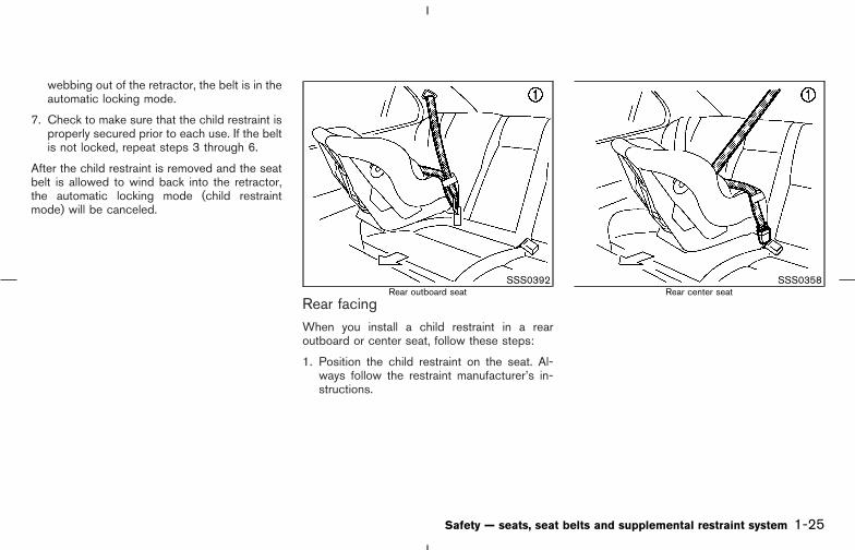
7. Check to make sure that the child restraint isproperly secured prior to each use. If the beltis not locked, repeat steps 3 through 6.
After the child restraint is removed and the seatbelt is allowed to wind back into the retractor,the automatic locking mode (child restraintmode) will be canceled.
Rear facingWhen you install a child restraint in a rearoutboard or center seat, follow these steps:
1. Position the child restraint on the seat. Al-ways follow the restraint manufacturer’s in-structions.
SSS0392Rear outboard seat
SSS0358Rear center seat
Safety — seats, seat belts and supplemental restraint system 1-25
� 04.8.3/Z50-D/V5.0 �

2. Route the seat belt tongue through the childrestraint and insert it into the buckle until youhear and feel the latch engage.Be sure to follow the child restraint manufac-turer’s instructions for belt routing.
3. Pull on the shoulder belt until all of the belt isfully extended. At this time, the belt retractoris in the automatic locking mode (child re-straint mode). It reverts back to emergencylocking mode when the belt is fully retracted.
4. Allow the belt to retract. Pull up on the belt toremove any slack in the belt.
SSS0335 SSS0258A SSS0259A
1-26 Safety — seats, seat belts and supplemental restraint system
� 04.8.3/Z50-D/V5.0 �
5. Before placing the child in the child restraint,use force to push the child restraint from sideto side, and tug it forward to make sure that itis securely held in place. It should not movemore than 1 inch (25 mm). If it does movemore than 1 inch (25 mm), pull again on theshoulder belt to further tighten the childrestraint. If unable to properly secure therestraint, move the restraint to another rearseating position and try again, or try a differ-ent child restraint. Not all child restraints fit inall types of vehicles.
6. Check that the retractor is in the automaticlocking mode by trying to pull more belt out ofthe retractor. If you cannot pull any more belt
webbing out of the retractor, the belt is in theautomatic locking mode.
7. Check to make sure that the child restraint isproperly secured prior to each use. If the beltis not locked, repeat steps 3 through 6.
After the child restraint is removed and the seatbelt is allowed to wind back into the retractor,the automatic locking mode (child restraintmode) is canceled.
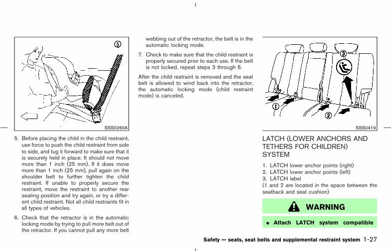
LATCH (LOWER ANCHORS ANDTETHERS FOR CHILDREN)SYSTEM
1. LATCH lower anchor points (right)2. LATCH lower anchor points (left)3. LATCH label(1 and 2 are located in the space between theseatback and seat cushion)
WARNING
� Attach LATCH system compatible
SSS0260A SSS0419
Safety — seats, seat belts and supplemental restraint system 1-27
� 04.8.3/Z50-D/V5.0 �

child restraints only at the locationsshown. If a child restraint is not se-cured properly, your child could beseriously injured or killed in an acci-dent.
� Do not secure a child restraint in thecenter rear seating position using theLATCH system anchors. The child re-straint will not be secured properly.
� The LATCH system anchors are de-signed to withstand only those loadsimposed by correctly fitted child re-straints. Under no circumstance arethey to be used for adult seat belts orharnesses.
Some child restraints include two rigid orwebbing-mounted attachments that can be con-nected to two anchors located at certain seatingpositions in your vehicle. This system is knownas the LATCH (Lower Anchors and Tethers forCHildren) system. This system may also bereferred to as the ISOFIX or ISOFIX compatiblesystem. With this system, you do not have to usea vehicle seat belt to secure the child restraint.Your vehicle is equipped with special anchorpoints that are used with LATCH system com-
patible child restraints. Check your child restraintfor a label stating that it is compatible with theLATCH system. This information may also be inthe child restraint owner’s manual. If you havesuch a child restraint, refer to the illustration forthe seating positions equipped with LATCHsystem anchors which can be used to secure thechild restraint.
The LATCH system anchors are located at therear of the seat cushion near the seatback. Alabel is attached to the seatback to help youlocate the LATCH system anchors.
Some child restraints may also require the use ofa top tether strap. See “Top tether strap childrestraint” later in this section for installationinstructions.
When installing a child restraint, carefully readand follow the instructions in this manual andthose supplied with the child restraint.
When you install a LATCH system compatiblechild restraint to the lower anchor attachments,follow these steps.
WARNING
Inspect the lower anchors by insertingyour fingers into the lower anchor areaand feeling to make sure there are noobstructions over the LATCH system an-chors, such as seat belt webbing or seatcushion material. The child restraint willnot be secured properly if the LATCHsystem anchors are obstructed.
1. To install the LATCH system compatible childrestraint, adjust the height of the child re-straint LATCH system anchor attachments tothe anchor points on the rear seat.
2. Insert the anchor attachments into the anchorpoints. If the child restraint is equipped with atop tether, see “Top tether strap child re-straint” later in this section for installationinstructions.
3. After attaching the child restraint and beforeplacing the child in it, use force to push thechild restraint from side to side and tug itforward to make sure that the child restraint issecurely held in place. It should not movemore than 1 inch (25 mm).
4. Check to make sure that the child restraint isproperly secured prior to each use.
1-28 Safety — seats, seat belts and supplemental restraint system
� 04.8.3/Z50-D/V5.0 �

TOP TETHER STRAP CHILDRESTRAINT
WARNING
� Child restraint anchor points are de-signed to withstand only those loadsimposed by correctly fitted child re-straints. Under no circumstances arethey to be used for adult seat belts orharnesses.
� After removing a rear seat head re-straint for top tether installation,store it securely to prevent it fromcausing injury to passengers or dam-age to the vehicle in case of suddenbraking or an accident. Always re-place it and adjust properly when toptether is no longer in use.
� The child restraint top tether strapmay be damaged by contact with thetonneau cover or items in the cargoarea. Remove the tonneau cover fromthe vehicle or secure it and any cargo.Your child could be seriously injuredor killed ina collision if the top tether
strap is damaged.
If your child restraint has a top tether strap, itmust be secured to the anchor point providedbehind its position.
First, adjust the seatback so that it is upright.Then secure the child restraint with the rear seatbelt or the LATCH system (outboard positions),as applicable. For the center position �C , re-move the anchor cover from the anchor point asillustrated. Keep the removed cover in a secureplace to prevent loss or damage.
Remove the head restraint from the seatback.Store it in a secure place. Position the top tetherstrap over the top of the seatback and secure itto the tether anchor bracket that provides the
SSS0234
Safety — seats, seat belts and supplemental restraint system 1-29
� 04.8.3/Z50-D/V5.0 �
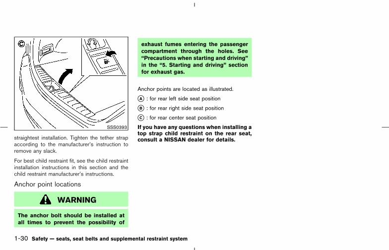
straightest installation. Tighten the tether strapaccording to the manufacturer’s instruction toremove any slack.
For best child restraint fit, see the child restraintinstallation instructions in this section and thechild restraint manufacturer’s instructions.
Anchor point locations
WARNING
The anchor bolt should be installed atall times to prevent the possibility of
exhaust fumes entering the passengercompartment through the holes. See“Precautions when starting and driving”in the “5. Starting and driving” sectionfor exhaust gas.
Anchor points are located as illustrated.
�A : for rear left side seat position
�B : for rear right side seat position
�C : for rear center seat position
If you have any questions when installing atop strap child restraint on the rear seat,consult a NISSAN dealer for details.
SSS0393
1-30 Safety — seats, seat belts and supplemental restraint system
� 04.8.3/Z50-D/V5.0 �

INSTALLATION ON FRONTPASSENGER SEAT
WARNING
� Never install a rear-facing child re-straint in the front passenger seat.Supplemental front air bags inflatewith great force. A rear-facing childrestraint could be struck by thesupplemental front air bag in a crashand could seriously injure or kill your
child.
� NISSAN recommends that child re-straints be installed in the rear seat.However, if you must install a frontfacing child restraint in the front pas-senger seat, move the passengerseat to the rearmost position.
� A child restraint with a top tetherstrap should not be used in the frontpassenger seat.
� The three-point seat belt in your ve-hicle is equipped with an automatic
locking mode retractor which mustbe used when installing a child re-straint.
� Failure to use the retractor’s lockingmode will result in the child restraintnot being properly secured. The re-straint could tip over or otherwise beunsecured and cause injury to thechild in a sudden stop or collision.
SSS0300A
Safety — seats, seat belts and supplemental restraint system 1-31
� 04.8.3/Z50-D/V5.0 �

Front facing
If you must install a child restraint in the frontseat, follow these steps:
1. Position the child restraint on the front pas-senger seat. It should be placed in a frontfacing direction only. Move the seat to therearmost position. Adjust the head restraint toits highest position. Always follow the childrestraint manufacturer’s instructions. Childrestraints for infants must be used inthe rear facing direction and thereforemust not be used in the front seat.
The back of the child restraint should be
secured against the vehicle seatback. If nec-essary, adjust or remove the head restraint toobtain the correct child restraint fit. See“Head restraint adjustment” earlier in thissection. If the head restraint is removed, storeit in a secure place. Be sure to install thehead restraint when the child restraint isremoved. If the seating position does nothave an adjustable head restraint and it isinterfering with the proper child restraint fit,try another seating position or a differentchild restraint.
2. Route the seat belt tongue through the childrestraint and insert it into the buckle until youhear and feel the latch engage. Be sure tofollow the child restraint manufacturer’s in-structions for belt routing.
SSS0301B SSS0360
1-32 Safety — seats, seat belts and supplemental restraint system
� 04.8.3/Z50-D/V5.0 �

3. Pull on the shoulder belt until all of the belt isfully extended. At this time, the belt retractoris in the automatic locking mode (child re-straint mode). It reverts back to emergencylocking mode when the belt is fully retracted.
4. Allow the belt to retract. Pull up on the belt toremove any slack in the belt.
5. Before placing the child in the child restraint,use force to push the child restraint from sideto side, and tug it forward to make sure that itis securely held in place. It should not movemore than 1 inch (25 mm). If it does movemore than 1 inch (25 mm), pull again on theshoulder belt to further tighten the childrestraint. If unable to properly secure therestraint, move the restraint to another rearseating position and try again, or try a differ-ent child restraint. Not all child restraints fit inall types of vehicles.
6. Check that the retractor is in the automaticlocking mode by trying to pull more belt out ofthe retractor. If you cannot pull any more belt
SSS0361 SSS0424 SSS0302E
Safety — seats, seat belts and supplemental restraint system 1-33
� 04.8.3/Z50-D/V5.0 �
webbing out of the retractor, the belt is in theautomatic locking mode.
7. Check to make sure that the child restraint isproperly secured prior to each use. If the lapbelt is not locked, repeat steps 3 through 6.
After the child restraint is removed and the seatbelt is allowed to wind back into the retractor,the automatic locking mode (child restraintmode) will be canceled.
PRECAUTIONS ON BOOSTERSEATS
WARNING
� Infants and small children should al-ways be placed in an appropriatechild restraint while riding in the ve-hicle. Failure to use a child restraintor booster seat can result in seriousinjury or death.
� Infants and small children shouldnever be carried on your lap. It is notpossible for even the strongest adultto resist the forces of a severe acci-dent. The child could be crushed be-tween the adult and parts of the ve-hicle. Also, do not put the same seatbelt around both your child and your-self.
� NISSAN recommends that thebooster seat be installed in the rearseat. According to accident statistics,children are safer when properly re-strained in the rear seat than in thefront seat.
� A booster seat must only be installedin a seating position that has alap/shoulder belt. Failure to use athree-point type seat belt with abooster seat can result in a seriousinjury in sudden stop or collision.
� An improperly installed booster seatcould lead to serious injury or deathin an accident.
BOOSTER SEATS
1-34 Safety — seats, seat belts and supplemental restraint system
� 04.8.3/Z50-D/V5.0 �
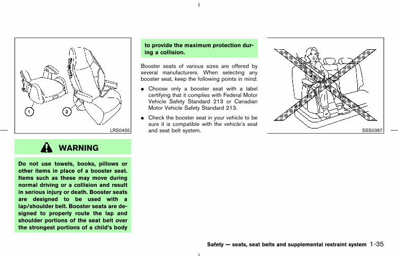
WARNING
Do not use towels, books, pillows orother items in place of a booster seat.Items such as these may move duringnormal driving or a collision and resultin serious injury or death. Booster seatsare designed to be used with alap/shoulder belt. Booster seats are de-signed to properly route the lap andshoulder portions of the seat belt overthe strongest portions of a child’s body
to provide the maximum protection dur-ing a collision.
Booster seats of various sizes are offered byseveral manufacturers. When selecting anybooster seat, keep the following points in mind:
� Choose only a booster seat with a labelcertifying that it complies with Federal MotorVehicle Safety Standard 213 or CanadianMotor Vehicle Safety Standard 213.
� Check the booster seat in your vehicle to besure it is compatible with the vehicle’s seatand seat belt system.LRS0455 SSS0387
Safety — seats, seat belts and supplemental restraint system 1-35
� 04.8.3/Z50-D/V5.0 �
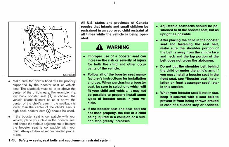
� Make sure the child’s head will be properlysupported by the booster seat or vehicleseat. The seatback must be at or above thecenter of the child’s ears. For example, if alow back booster seat �1 is chosen, thevehicle seatback must be at or above thecenter of the child’s ears. If the seatback islower than the center of the child’s ears, ahigh back booster seat �2 should be used.
� If the booster seat is compatible with yourvehicle, place your child in the booster seatand check the various adjustments to be surethe booster seat is compatible with yourchild. Always follow all recommended proce-dures.
All U.S. states and provinces of Canadarequire that infants and small children berestrained in an approved child restraint atall times while the vehicle is being oper-ated.
WARNING
� Improper use of a booster seat canincrease the risk or severity of injuryfor both the child and other occu-pants of the vehicle.
� Follow all of the booster seat manu-facturer’s instructions for installationand use. When purchasing a boosterseat, be sure to select one which willfit your child and vehicle. It may notbe possible to properly install sometypes of booster seats in your ve-hicle.
� If the booster seat and seat belt arenot used properly, the risk of a childbeing injured in a collision or a sud-den stop greatly increases.
� Adjustable seatbacks should be po-sitioned to fit the booster seat, but asupright as possible.
� After placing the child in the boosterseat and fastening the seat belt,make sure the shoulder portion ofthe belt is away from the child’s faceand neck and the lap portion of thebelt does not cross the abdomen.
� Do not put the shoulder belt behindthe child or under the child’s arm. Ifyou must install a booster seat in thefront seat, see “Booster seat instal-lation on front passenger seat” laterin this section.
� When your booster seat is not in use,keep it secured with a seat belt toprevent it from being thrown aroundin case of a sudden stop or accident.
SSS0388
1-36 Safety — seats, seat belts and supplemental restraint system
� 04.8.3/Z50-D/V5.0 �

CAUTION
Remember that a booster seat left in aclosed vehicle can become very hot.Check the seating surface and bucklesbefore placing your child in the boosterseat.
BOOSTER SEAT INSTALLATIONON REAR SEAT OUTBOARD ORCENTER POSITIONS
CAUTION
Do not use the lap/shoulder belt auto-matic locking mode when using abooster seat with the seat belts. Whenyou install a booster seat in the rearseat, follow these steps:
1. Position the booster seat on the seat. Only
place it in a front facing direction. Alwaysfollow the booster seat manufacturer’s in-structions.
2. The booster seat should be positioned on thevehicle seat so that it is stable. If necessary,adjust or remove the head restraint to obtainthe correct booster seat fit. See “Head re-straint adjustment” earlier in this section. Ifthe head restraint is removed, store it in asecure place. Be sure to install the headrestraint when the booster seat is removed. Ifthe seating position does not have an adjust-able head restraint and it is interfering withthe proper booster seat fit, try another seat-ing position or a different booster seat.
SSS0389Outboard position
SSS0390Center position
Safety — seats, seat belts and supplemental restraint system 1-37
� 04.8.3/Z50-D/V5.0 �
3. Position the lap portion of the seat belt lowand snug on the child’s hips. Be sure tofollow the booster seat manufacturer’s in-structions for adjusting the belt routing.
4. Pull the shoulder belt portion of the seat belttoward the retractor to take up extra slack. Besure the shoulder belt is positioned acrossthe top, middle portion of the child’s shoul-der. Be sure to follow the booster seat manu-facturer’s instructions for adjusting the beltrouting.
5. Follow the warnings, cautions and instruc-tions for properly fastening a seat belt shownin the “Three-point type seat belt with retrac-tor” earlier in this section.
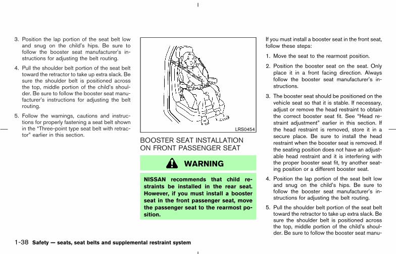
BOOSTER SEAT INSTALLATIONON FRONT PASSENGER SEAT
WARNING
NISSAN recommends that child re-straints be installed in the rear seat.However, if you must install a boosterseat in the front passenger seat, movethe passenger seat to the rearmost po-sition.
If you must install a booster seat in the front seat,follow these steps:
1. Move the seat to the rearmost position.
2. Position the booster seat on the seat. Onlyplace it in a front facing direction. Alwaysfollow the booster seat manufacturer’s in-structions.
3. The booster seat should be positioned on thevehicle seat so that it is stable. If necessary,adjust or remove the head restraint to obtainthe correct booster seat fit. See “Head re-straint adjustment” earlier in this section. Ifthe head restraint is removed, store it in asecure place. Be sure to install the headrestraint when the booster seat is removed. Ifthe seating position does not have an adjust-able head restraint and it is interfering withthe proper booster seat fit, try another seat-ing position or a different booster seat.
4. Position the lap portion of the seat belt lowand snug on the child’s hips. Be sure tofollow the booster seat manufacturer’s in-structions for adjusting the belt routing.
5. Pull the shoulder belt portion of the seat belttoward the retractor to take up extra slack. Besure the shoulder belt is positioned acrossthe top, middle portion of the child’s shoul-der. Be sure to follow the booster seat manu-
LRS0454
1-38 Safety — seats, seat belts and supplemental restraint system
� 04.8.3/Z50-D/V5.0 �

facturer’s instructions for adjusting the beltrouting.
6. Follow the warnings, cautions and instruc-tions for properly fastening a seat belt shownin the “Three-point type seat belt with retrac-tor” earlier in this section.
PRECAUTIONS ONSUPPLEMENTAL RESTRAINTSYSTEM
This Supplemental Restraint System (SRS) sec-tion contains important information concerningthe driver and passenger front impact supple-mental air bags, front seat side-impact supple-mental air bags, curtain side-impact and rolloverair bags and front seat pre-tensioner seat belts.Supplemental front impact air bag system:This system can help cushion the impact force tothe face and chest of the driver and frontpassenger in certain frontal collisions.Supplemental side-impact air bag system:This system can help cushion the impact force tothe chest area of the driver and front passengerin certain side impact collisions. The front seatside-impact supplemental air bags are designedto inflate on the side where the vehicle isimpacted.Supplemental curtain side-impact and roll-over air bag system: This system can helpcushion the impact force to the head of occu-pants in front and rear outboard seating posi-tions in certain side impact or rollover collisions.In a side impact, the curtain air bags are de-signed to inflate on the side where the vehicle isimpacted. In a rollover, both curtain air bags aredesigned to inflate and remain inflated for awhile.
These supplemental restraint systems are de-signed to supplement the crash protectionprovided by the driver and passenger seat beltsand are not a substitute for them. Seat beltsshould always be correctly worn and the occu-pant seated a suitable distance away from thesteering wheel, instrument panel, door finishersand side roof rails. (See “Seat belts” earlier inthis section for instructions and precautions onseat belt usage.)
After turning the ignition switch to the ONposition, the supplemental air bag warninglight illuminates. The supplemental air bagwarning light will turn off after about 7seconds if the systems are operational.
SUPPLEMENTAL RESTRAINTSYSTEM
Safety — seats, seat belts and supplemental restraint system 1-39
� 04.8.3/Z50-D/V5.0 �

WARNING
� The supplemental front air bags ordi-narily will not inflate in the event of aside impact, rear impact, rollover, orlower severity frontal collision. Al-ways wear your seat belts to helpreduce the risk or severity of injury invarious kinds of accidents.
� The seat belts and the supplementalfront air bags are most effective
when you are sitting well back andupright in the seat. Supplementalfront air bags inflate with great force.If you are unrestrained, leaning for-ward, sitting sideways or out of posi-tion in any way, you are at greaterrisk of injury or death in a crash. Youmay also receive serious or fatal in-juries from the supplemental front airbag if you are up against it when itinflates. Always sit back against theseatback and as far away as practical
from the steering wheel or instru-ment panel. Always use the seatbelts.
� The driver and front passenger seatbelt buckles are equipped with sen-sors that detect if the seat belts arefastened. The air bag system moni-tors the severity of a collision andthen inflates the air bags based onbelt usage. Failure to properly wearseat belts can increase the risk orseverity of injury in an accident.
� Keep hands on the outside of thesteering wheel. Placing them insidethe steering wheel rim could increasethe risk that they are injured whenthe supplemental front air bag in-flates.
� Never let children ride unrestrainedor extend their hands or face out ofthe window. Do not attempt to holdthem in your lap or arms. Some ex-amples of dangerous riding positionsare shown in the previous illustra-tions. Pre-teens and children should
SSS0131B
1-40 Safety — seats, seat belts and supplemental restraint system
� 04.8.3/Z50-D/V5.0 �
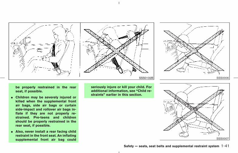
be properly restrained in the rearseat, if possible.
� Children may be severely injured orkilled when the supplemental frontair bags, side air bags or curtainside-impact and rollover air bags in-flate if they are not properly re-strained. Pre-teens and childrenshould be properly restrained in therear seat, if possible.
� Also, never install a rear facing childrestraint in the front seat. An inflatingsupplemental front air bag could
seriously injure or kill your child. Foradditional information, see “Child re-straints” earlier in this section.
SSS0132B SSS0006
SSS0007
Safety — seats, seat belts and supplemental restraint system 1-41
� 04.8.3/Z50-D/V5.0 �
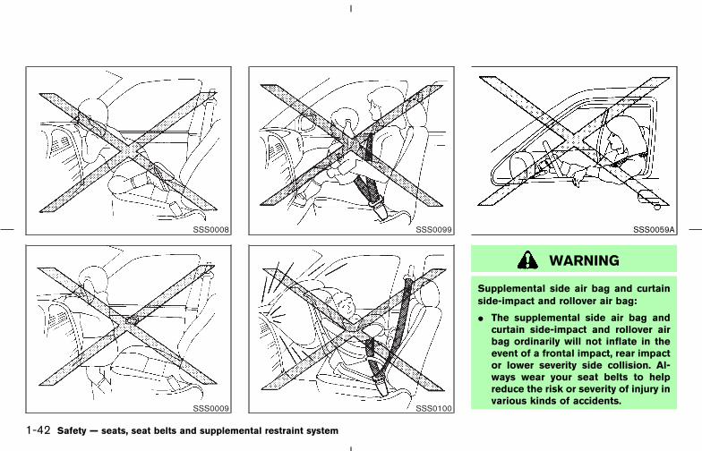
WARNING
Supplemental side air bag and curtainside-impact and rollover air bag:
� The supplemental side air bag andcurtain side-impact and rollover airbag ordinarily will not inflate in theevent of a frontal impact, rear impactor lower severity side collision. Al-ways wear your seat belts to helpreduce the risk or severity of injury invarious kinds of accidents.
SSS0008
SSS0009
SSS0099
SSS0100
SSS0059A
1-42 Safety — seats, seat belts and supplemental restraint system
� 04.8.3/Z50-D/V5.0 �

� The seat belts, the supplemental sideair bags and curtain side-impact androllover air bags are most effectivewhen you are sitting well back andupright in the seat. The side air bagand curtain side-impact and rolloverair bag inflate with great force. Donot allow anyone to place their hand,leg or face near the side air bag onthe side of the seatback of the frontseat or near the side roof rails. Do notallow anyone sitting in the front
seats or rear outboard seats to ex-tend their hand out of the window orlean against the door. Some ex-amples of dangerous riding positionsare shown in the previous illustra-tions.
� When sitting in the rear seat, do nothold onto the seatback of the frontseat. If the side air bag inflates, youmay be seriously injured. Be espe-cially careful with children, whoshould always be properly restrained.
� Do not use seat covers on the frontseatbacks. They may interfere withsupplemental side air bag inflation.
SSS0188A SSS0140 SSS0159
Safety — seats, seat belts and supplemental restraint system 1-43
� 04.8.3/Z50-D/V5.0 �

1. Crash zone sensor2. Supplemental front air bag modules3. Supplemental curtain side-impact and roll-
over air bags4. Supplemental curtain side-impact and roll-
over air bag modules
5. Seat belt pre-tensioner retractor6. Satellite sensors7. Diagnosis sensor unit8. Supplemental side air bag modules
SSS0162
SSS0230
1-44 Safety — seats, seat belts and supplemental restraint system
� 04.8.3/Z50-D/V5.0 �

Supplemental front air bag system
The driver supplemental air bag is located in thecenter of the steering wheel; the front passengersupplemental air bag is mounted in the instru-ment panel above the glove box. These systemsare designed to meet optional certification re-quirements under U.S. regulations. They are alsopermitted in Canada. The optional certificationallows front air bags to be designed to inflatesomewhat less forcefully than previously. How-ever, all of the information, cautions andwarnings in this manual still apply andmust be followed. The front air bags aredesigned to inflate in higher severity frontalcollisions, although they may inflate if the forcesin another type of collision are similar to those ofa higher severity frontal impact. They may notinflate in certain frontal collisions. Vehicle dam-age (or lack of it) is not always an indication ofproper supplemental air bag operation.
The supplemental air bag system has dual stageinflators for both the driver and passenger airbags. The system monitors information from thecrash zone sensor, the diagnosis sensor unit andseat belt buckle sensors that detect if the seatbelts are fastened, inflator operation is based onthe severity of a collision and whether the seatbelts are being used. Only one front air bag mayinflate in a crash, depending on the crash sever-ity and whether the front occupants are belted or
unbelted. This does not indicate improper per-formance of the system. If you have any ques-tions about the performance of your air bagsystem, contact a NISSAN dealer.
When the supplemental front air bag inflates, afairly loud noise may be heard, followed byrelease of smoke. This smoke is not harmful anddoes not indicate a fire. Care should be takennot to inhale it, as it may cause irritation andchoking. Those with a history of a breathingcondition should get fresh air promptly.
Supplemental front air bags, along with the useof seat belts, helps to cushion the impact forceon the face and chest of the front occupants.They can help save lives and reduce seriousinjuries. However, an inflating front air bag maycause facial abrasions or other injuries. Front airbags do not provide restraint to the lower body.
The seat belts should be correctly worn and thedriver and passenger seated upright as far aspractical away from the steering wheel or instru-ment panel. The supplemental front air bagsinflate quickly in order to help protect the frontoccupants. Because of this, the force of the frontair bag inflating can increase the risk of injury ifthe occupant is too close to, or is against the airbag module during inflation. The air bag willdeflate quickly after the collision is over.
After turning the ignition switch to the ON
position, the supplemental air bag warninglight illuminates. The supplemental air bagwarning light will turn off after about 7seconds if the system is operational.
WARNING
� Do not place any objects on thesteering wheel pad or on the instru-ment panel. Also, do not place anyobjects between any occupant andthe steering wheel or instrumentpanel. Such objects may becomedangerous projectiles and cause in-jury if the supplemental front air baginflates.
� Immediately after inflation, severalfront air bag system components willbe hot. Do not touch them; you mayseverely burn yourself.
� No unauthorized changes should bemade to any components or wiring ofthe supplemental air bag system.This is to prevent accidental inflationof the air bag or damage to the airbag system.
Safety — seats, seat belts and supplemental restraint system 1-45
� 04.8.3/Z50-D/V5.0 �
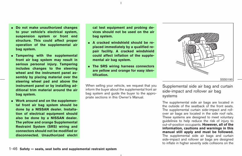
� Do not make unauthorized changesto your vehicle’s electrical system,suspension system or front endstructure. This could affect properoperation of the supplemental airbag system.
� Tampering with the supplementalfront air bag system may result inserious personal injury. Tamperingincludes changes to the steeringwheel and the instrument panel as-sembly by placing material over thesteering wheel pad and above theinstrument panel or by installing ad-ditional trim material around the airbag system.
� Work around and on the supplemen-tal front air bag system should bedone by a NISSAN dealer. Installa-tion of electrical equipment shouldalso be done by a NISSAN dealer.The yellow and orange SupplementalRestraint System (SRS) wiring andconnectors should not be modified ordisconnected. Unauthorized electri
cal test equipment and probing de-vices should not be used on the airbag system.
� A cracked windshield should be re-placed immediately by a qualified re-pair facility. A cracked windshieldcould affect inflation of the supple-mental air bag system.
� The SRS wiring harness connectorsare yellow and orange for easy iden-tification.
When selling your vehicle, we request that youinform the buyer about the supplemental front airbag system and guide the buyer to the appro-priate sections in this Owner’s Manual.
Supplemental side air bag and curtainside-impact and rollover air bagsystemsThe supplemental side air bags are located inthe outside of the seatback of the front seats.The supplemental curtain side-impact and roll-over air bags are located in the side roof rails.These systems are designed to meet voluntaryguidelines to help reduce the risk of injury toout-of-position occupants. However, all of theinformation, cautions and warnings in thismanual still apply and must be followed.The supplemental side air bags and curtainside-impact and rollover air bags are designedto inflate in higher severity side collisions on the
SSS0190
1-46 Safety — seats, seat belts and supplemental restraint system
� 04.8.3/Z50-D/V5.0 �

side where the vehicle is impacted, althoughthey may inflate if the forces in another type ofcollision are similar to those of a higher severityside impact. They are designed to inflate on theside where the vehicle is impacted. They may notinflate in certain side collisions. Vehicle damage(or lack of it) is not always an indication of propersupplemental side air bag and curtain side-impact and rollover air bag operation.
Curtain side-impact and rollover air bags arealso designed to inflate in certain types of roll-over collisions or near rollovers.
When the supplemental side air bag and curtainside-impact/rollover air bag inflate, a fairly loudnoise may be heard, followed by release ofsmoke. This smoke is not harmful and does notindicate a fire. Care should be taken not to inhaleit, as it may cause irritation and choking. Thosewith a history of a breathing condition should getfresh air promptly.
Supplemental side air bags, along with the useof seat belts, help to cushion the impact force onthe chest of the front occupants. Curtain side-impact and rollover air bags help to cushion theimpact force to the head of occupants in thefront and rear outboard seating positions. Theycan help save lives and reduce serious injuries.However, an inflating side air bag and curtainside-impact/rollover air bag may cause abra-sions or other injuries. Supplemental side airbags and curtain side-impact and rollover air
bags do not provide restraint to the lower body.
The seat belts should be correctly worn and thedriver and passenger seated upright as far aspractical away from the side air bag. Rear seatpassengers should be seated as far away aspractical from the door finishers and side roofrails. The side air bags and curtain side-impactand rollover air bags inflate quickly in order tohelp protect the front occupants. Because ofthis, the force of the side air bag and curtainside-impact/rollover air bag inflating can in-crease the risk of injury if the occupant is tooclose to, or is against, these air bag modulesduring inflation. The side air bag will deflatequickly after the collision is over.
The curtain side-impact and rollover air bags willremain inflated for a while.
After turning the ignition switch to the ONposition, the supplemental air bag warninglight illuminates. The air bag warning lightwill turn off after about 7 seconds if thesystems are operational.
WARNING
� Do not place any objects near theseatback of the front seats. Also, do
not place any objects (an umbrella,bag, etc.) between the front door fin-isher and the front seat. Such objectsmay become dangerous projectilesand cause injury if the side air baginflates.
� Right after inflation, several side airbag and curtain side-impact and roll-over air bag system components willbe hot. Do not touch them; you mayseverely burn yourself.
� No unauthorized changes should bemade to any components or wiring ofthe side air bag and curtain side-impact/rollover air bag system. Thisis to prevent accidental inflation ofthe side air bag and curtain side-impact/rollover air bag or damage tothe side air bag and curtain side-impact/rollover air bag system.
� Do not make unauthorized changesto your vehicle’s electrical system,suspension system or side panel.This could affect proper operation ofthe supplemental side air bag and
Safety — seats, seat belts and supplemental restraint system 1-47
� 04.8.3/Z50-D/V5.0 �

curtain side-impact/rollover air bagsystem.
� Tampering with the supplementalsystem may result in serious per-sonal injury. For example, do notchange the front seats by placingmaterial near the seatback or by in-stalling additional trim material, suchas seat covers, around the side airbag.
� Work around and on the side air bagand curtain side-impact/rollover airbag system should be done by aNISSAN dealer. Installation of elec-trical equipment should also be doneby a NISSAN dealer. The SRS wiringharnesses* should not be modified ordisconnected. Unauthorized electri-cal test equipment and probing de-vices should not be used on the sideair bag system.
* The SRS wiring harnesses are cov-ered with yellow and orange insula-tion either just before the harnessconnectors or over the complete har-ness for easy identification.
When selling your vehicle, we request that youinform the buyer about the side air bag andcurtain side-impact/rollover air bag system andguide the buyer to the appropriate sections inthis Owner’s Manual.
Pre-tensioner seat belt system (Forfront seats)
WARNING
� The pre-tensioner seat belt cannot bereused after activation. It must bereplaced together with the retractorand buckle as a unit.
� If the vehicle becomes involved in afrontal collision but the pre-tensioneris not activated, be sure to have thepre-tensioner system checked and, ifnecessary, replaced by a NISSANdealer.
� No unauthorized changes should bemade to any components or wiring ofthe pre-tensioner seat belt system.This is to prevent accidental activa-tion of the pre-tensioner seat belt ordamage to the pre-tensioner seat
belt operation. Tampering with thepre-tensioner seat belt system mayresult in serious personal injury.
� Work around and on the pre-tensioner seat belt system should bedone by a NISSAN dealer. Installa-tion of electrical equipment shouldalso be done by a NISSAN dealer.Unauthorized electrical test equip-ment and probing devices should notbe used on the pre-tensioner seatbelt system.
� If you need to dispose of the pre-tensioner or scrap the vehicle, con-tact a NISSAN dealer. Correct pre-tensioner disposal procedures areset forth in the appropriate NISSANService Manual. Incorrect disposalprocedures could cause personalinjury.
The front seat pre-tensioner seat belt systemactivates in conjunction with the supplementalfront air bag system. Working with the seat beltretractor, it helps tighten the seat belt when thevehicle becomes involved in certain types of
1-48 Safety — seats, seat belts and supplemental restraint system
� 04.8.3/Z50-D/V5.0 �

collisions, helping to restrain front seat occu-pants.
Also, the front seat pre-tensioner seat belt sys-tem activates in conjunction with the supple-mental side-impact/rollover air bag system.Working with the seat belt retractor, it helpstighten the seat belt when the vehicle becomesinvolved in certain types of rollover collisions orrear rollovers.
The pre-tensioner is encased with the seat belt’sretractor. These seat belts are used the same asconventional seat belts.
When the pre-tensioner seat belt activates,smoke is released and a loud noise may beheard. The smoke is not harmful, but care shouldbe taken not to inhale it as it may cause irritationand choking. Those with a history of a breathingcondition should get fresh air promptly.
If any abnormality occurs in the pre-tensionerseat belt system, the supplemental air bag warn-ing light will not come on, will flash inter-mittently or will turn on for 7 seconds and remainon after the ignition switch has been turned tothe ON or START position. In this case, thepre-tensioner seat belt may not function prop-erly. They must be checked and repaired. Takeyour vehicle to a NISSAN dealer.
When selling your vehicle, we request that you
inform the buyer about the pre-tensioner seatbelt system and guide the buyer to the appro-priate sections in this Owner’s Manual.
SUPPLEMENTAL AIR BAGWARNING LABELSWarning labels about the supplemental front airbag and supplemental side-impact air bag sys-tems are placed in the vehicle as shown in theillustration.
�1 SRS air bagThe warning labels are located on the surface ofthe sun visors.
�2 SRS side-impact air bagThe warning label is located on the side of thepassenger’s side center pillar.
SSS0330
Safety — seats, seat belts and supplemental restraint system 1-49
� 04.8.3/Z50-D/V5.0 �

SUPPLEMENTAL AIR BAGWARNING LIGHT
The supplemental air bag warning light, display-ing in the instrument panel, monitors thecircuits of the supplemental front air bag,supplemental side air bag and curtain side-impact and rollover air bag systems, and pre-tensioner seat belt. The circuits monitored by theair bag warning light are the diagnosis sensorunit, satellite sensors, front air bag modules, sideair bag modules, curtain side-impact/rollover airbag modules, and pre-tensioner seat belt and allrelated wiring.
After turning the ignition switch to the ON
position, the supplemental air bag warning lightilluminates. The supplemental air bag warninglight will turn off after about 7 seconds if thesystem is operational.
If any of the following conditions occur, thesupplemental front air bag, supplemental side airbag and curtain side-impact/rollover air bagsystems, and pre-tensioner seat belt need ser-vicing:
� The supplemental air bag warning light re-mains on after approximately 7 seconds.
� The supplemental air bag warning lightflashes intermittently.
� The supplemental air bag warning light doesnot come on at all.
Under these conditions, the supplemental frontair bags, supplemental side air bags, curtainside-impact/rollover air bags and/or pre-tensioner seat belt may not operate properly.They must be checked and repaired. Take yourvehicle to a NISSAN dealer.
WARNING
If the supplemental air bag warninglight is on, it could mean that the
supplemental front air bag, supplemen-tal side air bag, curtain side-impact/rollover air bag systems and/or pre-tensioner seat belt systems will not op-erate in an accident. To help avoid injuryto yourself or others, have your vehiclechecked by a NISSAN dealer as soon aspossible.
Repair and replacement procedureThe supplemental front air bags, supplementalside air bags, curtain side-impact/rollover airbags and pre-tensioner seat belt are designed toactivate on a one-time-only basis. As a reminder,unless it is damaged, the supplemental air bagwarning light will remain illuminated after inflationhas occurred. Repair and replacement of thesesystems should be done only by a NISSANdealer.
When maintenance work is required on thevehicle, the supplemental front air bags, side airbags, curtain side-impact/rollover air bags, re-lated parts and pre-tensioner seat belt should bepointed out to the person conducting the main-tenance. The ignition switch should always be inthe LOCK position when working under thehood or inside the vehicle.
SPA1097
1-50 Safety — seats, seat belts and supplemental restraint system
� 04.8.3/Z50-D/V5.0 �

WARNING
� Once a supplemental front air bag,supplemental side air bag or curtainside-impact/rollover air bag has in-flated, the air bag module will notfunction again and must be replaced.Additionally, if any of the supplemen-tal front air bags inflate, the activatedpre-tensioner seat belts must also bereplaced. The air bag module andpre-tensioner seat belt systemshould be replaced by a NISSANdealer. The air bag module and pre-tensioner seat belt system cannot berepaired.
� The supplemental front air bag, sideair bag and curtain side-impact/rollover air bag and systemsand the pre-tensioner seat belt sys-tem should be inspected by aNISSAN dealer if there is any damageto the front end or side portion of thevehicle.
� If you need to dispose of thesesupplemental systems or scrap the
vehicle, contact a NISSAN dealer.Correct disposal procedures are setforth in the appropriate NISSAN Ser-vice Manual. Incorrect disposal pro-cedures could cause personal injury.
Safety — seats, seat belts and supplemental restraint system 1-51
� 04.8.3/Z50-D/V5.0 �

MEMO
1-52 Safety — seats, seat belts and supplemental restraint system
� 04.8.3/Z50-D/V5.0 �

MEMO
Safety — seats, seat belts and supplemental restraint system 1-53
� 04.8.3/Z50-D/V5.0 �

2 Instruments and controls
Instrument panel..................................................................... 2-2Meters and gauges ............................................................... 2-3
Speedometer and odometer ......................................... 2-4Tachometer ........................................................................ 2-4Engine coolant temperature gauge ............................. 2-5Fuel gauge ......................................................................... 2-5
Compass display (if so equipped) .................................... 2-6Warning/indicator lights and audible reminders ............ 2-9
Checking bulbs................................................................. 2-9Warning lights................................................................... 2-9Indicator lights ................................................................ 2-14Audible reminders.......................................................... 2-16
Security systems.................................................................. 2-17Vehicle security system (if so equipped) ................ 2-17NISSAN Vehicle Immobilizer System ....................... 2-18
Windshield wiper and washer switch ........................... 2-20Rear window wiper and washer switch ....................... 2-21Rear window and outside mirror defroster switch...... 2-21Headlight and turn signal switch ................................... 2-22
Xenon headlights (if so equipped) .......................... 2-22Headlight switch ........................................................... 2-22Daytime running light system (Canada only) ........ 2-25Instrument brightness control..................................... 2-26Turn signal switch ........................................................ 2-26
Fog light switch (if so equipped) .............................. 2-26Hazard warning flasher switch......................................... 2-27Horn ........................................................................................ 2-27Heated seats (if so equipped) ......................................... 2-28Vehicle dynamic control (VDC) off switch(if so equipped).................................................................... 2-29Power outlet.......................................................................... 2-29Storage .................................................................................. 2-30
Coin box........................................................................... 2-30Cellular phone holder ................................................... 2-31Cup holders .................................................................... 2-31Glove box ........................................................................ 2-32Console box.................................................................... 2-33Cargo net (if so equipped) ......................................... 2-34Tonneau cover (if so equipped)................................. 2-34
Windows................................................................................ 2-35Power windows.............................................................. 2-35
Sunroof (if so equipped) ................................................... 2-37Automatic sunroof ......................................................... 2-37
Interior lights ......................................................................... 2-39Ceiling light ..................................................................... 2-39Map light .......................................................................... 2-40Rear personal light ........................................................ 2-40Luggage light.................................................................. 2-41
� 04.8.3/Z50-D/V5.0 �

Vanity mirror light (if so equipped) ................................. 2-41HomeLink Universal Transceiver (if so equipped).... 2-41
Programming HomeLink ............................................ 2-42Programming HomeLink for Canadiancustomers ........................................................................ 2-44Operating the HomeLink UniversalTransceiver ...................................................................... 2-44
Programming trouble diagnosis ................................. 2-44Clearing the programmed information...................... 2-44Reprogramming a single HomeLink button.......... 2-45If your vehicle is stolen................................................. 2-45
� 04.8.3/Z50-D/V5.0 �

1. Headlight, fog light (if so equipped) and turnsignal switch
2. Trip odometer reset button3. Instrument brightness control switch4. Meters/gauges5. Windshield/rear window wiper and washer
switch6. Hazard warning flasher switch7. Center ventilator8. Audio control9. Display/clock10. Rear window defroster and Heated outside
mirror (if so equipped) switch11. Display screen control and/or Navigation
system*12. Passenger supplemental air bag13. Side ventilator14. Headlight aiming control switch (if so
equipped)15. VDC (Vehicle dynamic control) off switch (if
so equipped) or Headlight aiming control (ifso equipped)
16. Steering switch for audio control (if soequipped)
17. Fuse box cover18. Tilting steering wheel lock lever19. Driver supplemental air bag/Horn20. Cruise control main/set switch21. Ignition switch/steering lock22. Heater/air conditioner control23. Coin box24. Outside mirror remote control25. Cellular phone holder26. AWD lock switch (AWD models)27. Heated seat switch (if so equipped)SSI0072
INSTRUMENT PANEL
2-2 Instruments and controls
� 04.8.3/Z50-D/V5.0 �
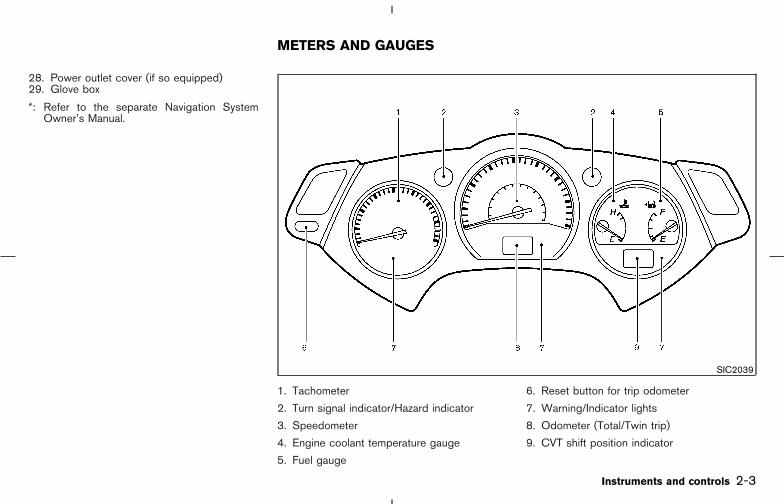
28. Power outlet cover (if so equipped)29. Glove box
*: Refer to the separate Navigation SystemOwner’s Manual.
1. Tachometer
2. Turn signal indicator/Hazard indicator
3. Speedometer
4. Engine coolant temperature gauge
5. Fuel gauge
6. Reset button for trip odometer
7. Warning/Indicator lights
8. Odometer (Total/Twin trip)
9. CVT shift position indicator
SIC2039
METERS AND GAUGES
Instruments and controls 2-3
� 04.8.3/Z50-D/V5.0 �

SPEEDOMETER AND ODOMETER
SpeedometerThe speedometer indicates vehicle speed.
Odometer/Twin trip odometerThe odometer �1 /twin trip odometer �2 aredisplayed when the ignition switch is in the ONposition.
The odometer records the total distance thevehicle has been driven.
The twin trip odometer records the distance ofindividual trips.
Changing the display:
Pushing the reset button �3 located on the leftside of the meter panel changes the display asfollows:
TRIP A → TRIP B → TRIP A
Resetting the trip odometer:
Pushing the reset button for more than 1 secondresets the trip odometer to zero.
Elapsed time, driving distance and averagespeed information is also available. Refer to“How to use TRIP button” in the “4. Displayscreen, heater, air conditioner and audio sys-tems” section later in this manual.
TACHOMETER
The tachometer indicates engine speed in revo-lutions per minute (rpm).
Do not rev engine into red zone �A .
CAUTION
When engine speed approaches the redzone, shift to a higher gear. Operatingthe engine in the red zone may causeserious engine damage.
SIC2175 SIC2041
2-4 Instruments and controls
� 04.8.3/Z50-D/V5.0 �
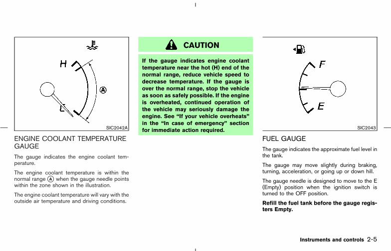
ENGINE COOLANT TEMPERATUREGAUGEThe gauge indicates the engine coolant tem-perature.
The engine coolant temperature is within thenormal range �A when the gauge needle pointswithin the zone shown in the illustration.
The engine coolant temperature will vary with theoutside air temperature and driving conditions.
CAUTION
If the gauge indicates engine coolanttemperature near the hot (H) end of thenormal range, reduce vehicle speed todecrease temperature. If the gauge isover the normal range, stop the vehicleas soon as safely possible. If the engineis overheated, continued operation ofthe vehicle may seriously damage theengine. See “If your vehicle overheats”in the “In case of emergency” sectionfor immediate action required.
FUEL GAUGEThe gauge indicates the approximate fuel level inthe tank.
The gauge may move slightly during braking,turning, acceleration, or going up or down hill.
The gauge needle is designed to move to the E(Empty) position when the ignition switch isturned to the OFF position.
Refill the fuel tank before the gauge regis-ters Empty.
SIC2042A SIC2043
Instruments and controls 2-5
� 04.8.3/Z50-D/V5.0 �

The low fuel warning light comes on whenthe fuel tank is getting low. Refuel as soonas it is convenient, preferably before thegauge reaches E. There will be a smallreserve of fuel in the tank when the fuelgauge needle reaches E.
The indicates that the fuel filler lid islocated on the driver’s side of the vehicle.
CAUTION
� If the vehicle runs out of fuel, themalfunction indicator lamp
(MIL) may come on. Refuel as soonas possible. After a few driving trips,the lamp should turn off. If thelamp remains on after a few drivingtrips, have the vehicle inspected by aNISSAN dealer.
� For additional information, see “Mal-function indicator lamp (MIL)” later inthis section.
When the COMPASS switch �A is pushed, thecompass display �B will indicate the directionthe vehicle is heading.
N: northE: eastS: southW: west
If the display reads “C”, calibrate the compassby driving the vehicle in 3 complete circles atless than 5 MPH (8 km/h).
You can also calibrate the compass by drivingyour vehicle on your everyday route. The com-pass will be calibrated once it has tracked 3complete circles.
SIC1901B
COMPASS DISPLAY (if soequipped)
2-6 Instruments and controls
� 04.8.3/Z50-D/V5.0 �

Zone variation change procedure
The difference between magnetic north andgeographical north is known as variance. Insome areas, this difference can sometimes begreat enough to cause false compass readings.Follow these instructions to set the variance foryour particular location if this happens:
1. Push the COMPASS switch for more than 3seconds. The current zone number will ap-pear in the display.
2. Find your current location and variance onenumber on the zone map �A .
3. Push the COMPASS switch until the newzone number appears in the display. After youstop pushing the switch in, the display willshow a compass direction within a few sec-onds.
Inaccurate compass direction:
1. With the display turned on, push the COM-PASS switch for 3 seconds, until the zoneselection comes up (a number will be dis-played in the mirror compass window).
2. Toggle until correct zone is found and releaseswitch.
3. It returns to the normal compass mode within10 seconds of no switch activity.SIC0611C
Instruments and controls 2-7
� 04.8.3/Z50-D/V5.0 �
4. If the vehicle changes zone, repeat steps 1thru 3. See map.
� If the compass deviates from the correctindication soon after repeated adjustment,have the compass checked at an authorizeddealer.
� The compass may not indicate the correctcompass point in tunnels or while driving upor down a steep hill.(The compass returns to the correct com-pass point when the vehicle moves to an areawhere the geomagnetism is stabilized.)
CAUTION
� Do not install a ski rack, antenna,etc., which are attached to the vehicleby means of a magnet. They affectthe operation of the compass.
� When cleaning the mirror, use a pa-per towel or similar material damp-ened with glass cleaner. Do not sprayglass cleaner directly on the mirror asit may cause the liquid cleaner toenter the mirror housing.
2-8 Instruments and controls
� 04.8.3/Z50-D/V5.0 �

All Wheel Drive (AWD) warning light(AWD models)
Low tire pressure warning light (if soequipped)
Cruise set indicator light
or Anti-lock Brake System (ABS)warning light
Low washer fluid warning light High beam indicator light (Blue)
or Brake warning lightP position selecting warning light (if soequipped)
Malfunction indicator lamp (MIL)
Charge warning light Seat belt warning light Security indicator light
Door open warning light Supplemental air bag warning light Slip indicator light (if so equipped)
Engine oil pressure warning lightAll Wheel Drive (AWD) LOCK indicatorlight (AWD models)
Turn signal/hazard indicator lights
Intelligent Key warning light (if soequipped)
Continuously Variable Transmission (CVT)indicator light
Vehicle Dynamic Control (VDC) off indi-cator light (if so equipped)
Low fuel warning light Cruise main switch indicator light
CHECKING BULBSApply the parking brake and turn the ignitionswitch to ON without starting the engine. Thefollowing lights will come on:
, or , , ,
The following lights come on briefly and then gooff:
, or , , , ,, , ,
If any light fails to come on, it may indicate aburned-out bulb or an open circuit in the elec-trical system. Have the system repairedpromptly.
WARNING LIGHTS
All wheel drive (AWD) warninglight (AWD models)
The warning light comes on when theignition switch is turned to ON. It turns off soonafter the engine is started.
If the AWD system malfunctions or the revolu-tion, or radius of the front and the rear wheel
WARNING/INDICATOR LIGHTSAND AUDIBLE REMINDERS
Instruments and controls 2-9
� 04.8.3/Z50-D/V5.0 �

differs, the warning light will either remain illumi-nated or blink. See “Using all wheel drive(AWD)” in the “5. Starting and driving” section.
CAUTION
� If the warning light comes on whiledriving, AWD mode will change to2WDmode. Reduce the vehicle speedand have your vehicle checked by aNISSAN dealer as soon as possible.
� Do not drive on dry hard surfaceroads in the LOCK mode.
� If the AWD warning light blinks whenyou are driving:
• blinks rapidly (about twice a sec-ond):Pull off the road in a safe area, andidle the engine. The driving modewill change to 2WD to prevent theAWD system from malfunctioning.If the warning light turns off, youcan drive again.
• blinks slowly (about once every 2seconds):
Pull off the road in a safe area, andidle the engine. Check that all tiresizes are the same, tire pressure iscorrect and tires are not worn.
If the warning light is still on after theabove operation, have your vehiclechecked by a NISSAN dealer as soon aspossible.
or Anti-lock brakesystem (ABS)warning light
After turning the ignition switch to the ONposition, the light will illuminate. The light will turnoff after about 2 seconds if the system isoperational.
If the light comes on while the engine is running,it may indicate that the anti-lock brake system isnot functioning properly. Have the systemchecked by a NISSAN dealer.
If an abnormality occurs in the system, theanti-lock function will cease but the ordinarybrakes will continue to operate normally. See“Anti-lock brake system (ABS)” in the “5. Start-ing and driving” section for further details.
If the light comes on while you are driving,contact a NISSAN dealer for repair.
or Brake warning light
This light functions for both the parking brakeand the foot brake systems.
Parking brake indicator:
When the ignition switch is in the ON position,the light comes on when the parking brake isapplied.
Low brake fluid warning light:
The light warns of a low brake fluid level. If thelight comes on while the engine is running withthe parking brake not applied, stop the vehicleand perform the following:
1. Check the brake fluid level. Add brake fluid asnecessary. See “Brake fluid” in the “8. Main-tenance and do-it-yourself” section.
2. If the brake fluid level is correct, have thewarning system checked by a NISSANdealer. Avoid high speed driving and abruptbraking.
If both the brake warning light and the anti-lock brake warning light come on simulta-neously, it may indicate the anti-lock brakesystem is not functioning properly. See “Anti-
2-10 Instruments and controls
� 04.8.3/Z50-D/V5.0 �

lock brake system (ABS) warning light” ear-lier in this section.
WARNING
� Your brake system may not be work-ing properly if the warning light is on.Driving could be dangerous. If youjudge it to be safe, drive carefully tothe nearest service station for re-pairs. Otherwise, have your vehicletowed because driving it could bedangerous.
� Pressing the brake pedal with theengine stopped and/or a low brakefluid level may increase your stop-ping distance and braking will re-quire greater pedal effort as well aspedal travel.
� If the brake fluid level is below theMINIMUM mark on the brake fluidreservoir, do not drive until the brakesystem has been checked at aNISSAN dealer.
Charge warning light
If the light comes on while the engine is running,it may indicate that the charging system is notfunctioning properly. Turn the engine off andcheck the generator belt. If the belt is loose,broken, missing or if the light remains on, see aNISSAN dealer immediately.
CAUTION
Do not continue driving if the generatorbelt is loose, broken or missing.
Door open warning lightThis light comes on when any of the doors arenot closed securely while the ignition switch isON.
Engine oil pressure warninglight
This light warns of low engine oil pressure. If thelight blinks or comes on during normal driving,pull off the road in a safe area, stop the engineimmediately and call a NISSAN dealer or otherauthorized repair shop.
The oil pressure warning light is not de-signed to indicate a low oil level. Use thedipstick to check the oil level. See “Engine
oil” in the “8. Maintenance and do-it-yourself”section.
CAUTION
Running the engine with the engine oilpressure warning light on could causeserious damage to the engine almostimmediately. Turn off the engine assoon as it is safe to do so.
Intelligent Key warning light(for Intelligent Key system) (ifso equipped)
This light comes on in green when it is possibleto turn the ignition switch.
When the light comes on in red, it is not possibleto turn the ignition switch.
� The warning light blinks in red when theIntelligent Key is outside the vehicle with theignition switch in the ACC or ON position.Confirm the location of the key as soon aspossible when the warning light blinks in red.Be sure to carry the Intelligent Key with youwhile driving the vehicle.
� The warning light goes off about 10 seconds
Instruments and controls 2-11
� 04.8.3/Z50-D/V5.0 �

after the Intelligent Key is brought inside thevehicle.
Low fuel warning light
This light comes on when the fuel in the tank isgetting low. Refuel as soon as it is convenient,preferably before the fuel gauge reaches E.
There will be a small reserve of fuel re-maining in the tank when the fuel gaugeneedle reaches E.
Low tire pressure warning light(if so equipped)
After the ignition switch is turned ON, this lightcomes on for about 1 second and then turns off.
This light warns of low tire pressure.
NISSAN’s low tire pressure warning system is atire pressure monitoring system. It monitors tirepressure of all tires except the spare. When thetire pressure monitoring system warning light islit, one or more of your tires is significantlyunder-inflated. You should stop and check yourtires as soon as possible, and inflate them to theproper pressure as indicated on the vehicle’s tireinformation placard. Driving on a significantlyunder-inflated tire causes the tire to overheatand can lead to tire failure.
Under-inflation also reduces fuel efficiency and
tire tread life, and may affect the vehicle’s han-dling and stopping ability. Each tire, includingthe spare, should be checked monthly whencold and set to the recommended inflation pres-sure as specified in the vehicle placard andOwner’s Manual. The recommended inflationpressure may also be found on the Tire andLoading Information label.
Low tire pressure warning:
If the vehicle is being driven with a low tirepressure (lower than 27 psi, 190 kPa), the lightwill illuminate and the chime will sound for about10 seconds. If you select the tire pressure in thedisplay, the FLAT TIRE warning message will bedisplayed.
For additional information, see “Low tire pres-sure warning system” in the “5. Starting anddriving” section and “Flat tire” in the “6. In caseof emergency” section. Also, you can check thepressure of all 4 tires on the display screen. See“Tire pressure information” in the “4. Displayscreen, heater, air conditioner and audio sys-tems” section.
WARNING
� If the light does not come on with thekey switch turned ON, have the ve-hicle checked by a NISSAN dealer assoon as possible.
� If the light comes on while driving,avoid sudden steering maneuvers orabrupt braking, reduce vehicle speed,pull off the road to a safe locationandstop the vehicle as soon as possible.Serious vehicle damage could occurand may lead to an accident andcould result in serious personal in-jury. Check the tire pressure for allfour tires. Adjust the tire pressure tothe recommended COLD tire pres-sure shown on the Tire and LoadingInformation label to turn the low tirepressure warning light OFF. If thelight still comes on while driving afteradjusting the tire pressure, a tire maybe flat. If you have a flat tire, replaceit with a spare tire as soon aspossible.
2-12 Instruments and controls
� 04.8.3/Z50-D/V5.0 �

� When a spare tire is mounted or awheel is replaced, the pressure ofthat tire will not be indicated and thelow tire pressure warning system willnot function. Contact a NISSANdealer as soon as possible for tirereplacement and/or systemresetting.
CAUTION
� The low tire pressure warning systemis not a substitute for the regular tirepressure check. Be sure to check thetire pressure regularly.
� If the vehicle is being driven atspeeds of less than 20 MPH (32km/h), the low tire pressure warningsystem may not operate correctly.
� Be sure to install the specified size oftires to the 4 wheels correctly.
Low washer fluid warning light
This light comes on when the washer tank fluid isat a low level. Add washer fluid as necessary.See “Window washer fluid” in the “8. Mainte-nance and do-it-yourself” section.
P position selecting warninglight (for Intelligent Key system)(if so equipped)
The light blinks in red and warning buzzer beepswhen the shift lever is not in the P position andyou are outside the vehicle with the IntelligentKey.
When the warning light blinks, move the shiftlever to the P position and return the ignitionswitch to the LOCK position.
Seat belt warning lightThe light and chime remind you to fasten seatbelts. The light illuminates whenever the ignitionswitch key is turned to ON, and will remainilluminated until the driver’s seat belt is fastened.At the same time, the chime will sound for about6 seconds unless the driver’s seat belt is se-curely fastened.
See “Seat belts” in the “1. Safety — seats, seatbelts and supplemental restraint system” sectionfor precautions on seat belt usage.
Supplemental air bag warninglight
After turning the ignition switch to the ONposition, the supplemental air bag warning lightwill illuminate. The supplemental air bag warninglight will turn off after about 7 seconds if thesystem is operational.
If any of the following conditions occur, thesupplemental front air bag, supplemental side airbag and curtain side-impact air bag systems,and pre-tensioner seat belt needs servicing andyour vehicle must be taken to a NISSAN dealer.
� The supplemental air bag warning light re-mains on after approximately 7 seconds.
� The supplemental air bag warning lightflashes intermittently.
� The supplemental air bag warning light doesnot come on at all.
Unless checked and repaired, the SupplementalRestraint System and/or the pre-tensioner seatbelt may not function properly. For additionalinformation, see “Supplemental restraint system”in the “1. Safety — seats, seat belts and supple-mental restraint system” section.
Instruments and controls 2-13
� 04.8.3/Z50-D/V5.0 �

WARNING
If the supplemental air bag warninglight is on, it could mean that thesupplemental front air bag, supplemen-tal side air bag, curtain air bag systemsand/or pre-tensioner seat belt systemwill not operate in an accident. To helpavoid injury to yourself or others, haveyour vehicle checked by a NISSANdealer as soon as possible.
INDICATOR LIGHTS
All wheel drive (AWD) LOCKindicator light (AWD models)
This light comes on when the ignition switch isturned to ON, and turns off within 1 second.
When selecting LOCK mode while the engine isrunning, this light will illuminate. See “Using allwheel drive (AWD)” in the “5. Starting anddriving” section.
Continuously variabletransmission (CVT) indicatorlight
When the ignition switch is turned ON, the lightcomes on for 2 seconds.
Cruise main switch indicatorlight
The light comes on when the cruise control mainswitch is pushed. The light goes out when themain switch is pushed again. When the cruisemain switch indicator light comes on, the cruisecontrol system is operational.
Cruise set indicator light
The light comes on while the vehicle speed iscontrolled by the cruise control system. If thelight blinks while the engine is running, it mayindicate the cruise control system is not func-tioning properly. Have the system checked by aNISSAN dealer.
High beam indicator light(Blue)
This light comes on when the headlight highbeam is on and goes out when the low beam isselected.
Malfunction indicator lamp(MIL)
If the malfunction indicator lamp comes onsteady or blinks while the engine is running, itmay indicate a potential emission control and/orCVT malfunction.
The malfunction indicator lamp may also comeon steady if the fuel filler cap is loose or missing,or if the vehicle runs out of fuel. Check to makesure the fuel filler cap is installed and closedtightly, and that the vehicle has at least threegallons of fuel in the fuel tank.
After a few driving trips, the lamp shouldturn off if no other potential emission controlsystem malfunction exists.
If this indicator lamp comes on continuously for20 seconds and then blinks for 10 secondswhen the engine is not running, it indicates thatthe vehicle is not ready for an emission controlsystem inspection/maintenance test. See“Readiness for inspection/maintenance (I/M)test” in the “9. Technical and consumer informa-tion” section of this manual.
Operation:
The malfunction indicator lamp will come on inone of two ways:
� Malfunction indicator lamp on steady — An
2-14 Instruments and controls
� 04.8.3/Z50-D/V5.0 �

emission control system and/or CVT mal-function has been detected. Turn the ignitionswitch to OFF and check the fuel filler cap. Ifthe fuel filler cap is loose or missing, tightenor install the cap and continue to drive thevehicle. The lamp should turn off after afew driving trips. If the lamp does notturn off after a few driving trips, have thevehicle inspected by a NISSAN dealer. Youdo not need to have your vehicle towed to thedealer.
� Malfunction indicator lamp blinking — Anengine misfire has been detected which maydamage the emission control system. To re-duce or avoid emission control system dam-age:
a) Do not drive at speeds above 45 MPH(72 km/h).
b) Avoid hard acceleration or deceleration.c) Avoid steep uphill grades.d) If possible, reduce the amount of cargo
being hauled or towed.
The malfunction indicator lamp may stopblinking and come on steady.
Have the vehicle inspected by a NISSANdealer. You do not need to have your vehicletowed to the dealer.
CAUTION
Continued vehicle operation withouthaving the emission control systemchecked and repaired as necessarycould lead to poor driveability, reducedfuel economy, and possible damage tothe emission control system.
Security indicator lightModel without Intelligent Key system:
This light blinks whenever the ignition switch is inthe LOCK, OFF or ACC position.
Model with Intelligent Key system:
This light blinks whenever the ignition switch isnot pushed in or the mechanical key is removedfrom the ignition switch.
This function indicates the security systemsequipped on the vehicle are operational.
For additional information, see “Security sys-tems” later in this section.
Slip indicator light (if soequipped)
This indicator will blink when the VDC system orthe traction control system is operating, thusalerting the driver to the fact that the roadsurface is slippery and the vehicle is nearing itstraction limits.
You may feel or hear the system working, but thisis normal.
The light will blink on for a few seconds after theVDC system stops limiting wheel spin.
The slip indicator light also comes on when youturn the ignition switch to ON. The light will turnoff after about 2 seconds if the system isoperational. If the light does not come on or gooff, have the traction control system checked bya NISSAN dealer.
Turn signal/hazard indicatorlights
The light flashes when the turn signal switchlever or hazard switch is turned on.
Instruments and controls 2-15
� 04.8.3/Z50-D/V5.0 �

Vehicle Dynamic Control(VDC) off indicator light (if soequipped)
After turning the ignition switch to the ONposition, the light will illuminate. The light will turnoff in about 2 seconds if the vehicle dynamiccontrol (VDC) system is operational.
The light comes on when the vehicle dynamiccontrol (VDC) off switch is pushed to OFF. Thisindicates the vehicle dynamic control systemand traction control system are not operating.When the vehicle dynamic control off indicatorlight and slip indicator light come on with thevehicle dynamic control system turned on, thislight alerts the driver to the fact that the vehicledynamic control system’s fail-safe mode is op-erating, that is the system may not be functioningproperly. Have the system checked by aNISSAN dealer. If a malfunction occurs in thesystem, the vehicle dynamic control systemfunction will be canceled but the vehicle is stilldriveable. For additional information, see “Ve-hicle dynamic control (VDC) system” in the “5.Starting and driving” section of this manual.
AUDIBLE REMINDERS
Key reminder chimeThe key reminder chime sounds if the driver’s
side door is opened while the key is left in theignition switch and the ignition switch is in the“ACC”, “OFF” or “LOCK” position. Remove thekey and take it with you when leaving the vehicle.
Light reminder chime
The light reminder chime sounds if the driver’sside door is opened while the headlight switch isat either the or position and theignition switch is in the ACC, OFF or LOCKposition.
Make sure to turn the light switch to the “OFF” or“AUTO” position when you leave the vehicle.
Seat belt warning chime
The chime will sound for about 6 seconds unlessthe drivers seat belt is securely fastened.
Brake pad wear warning
The disc brake pads have audible wear warn-ings. When a brake pad requires replacement, itwill make a high pitched scraping sound whenthe vehicle is in motion. Have the brakeschecked as soon as possible if the warningsound is heard.
Intelligent Key door buzzerWhen the chime or buzzer sounds from insideand outside the vehicle, check for the following:
� The ignition switch is turned to the LOCKposition.
� The Intelligent Key is not left inside thevehicle.
� Doors are closed securely.
� The selector lever is in the P position.
When the buzzer sounds, be sure to check boththe vehicle and the Intelligent Key.
See “INTELLIGENT KEY SYSTEM” in the “3.Pre-driving checks and adjustments” section.
2-16 Instruments and controls
� 04.8.3/Z50-D/V5.0 �
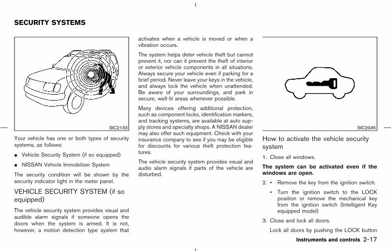
Your vehicle has one or both types of securitysystems, as follows:
� Vehicle Security System (if so equipped)
� NISSAN Vehicle Immobilizer System
The security condition will be shown by thesecurity indicator light in the meter panel.
VEHICLE SECURITY SYSTEM (if soequipped)
The vehicle security system provides visual andaudible alarm signals if someone opens thedoors when the system is armed. It is not,however, a motion detection type system that
activates when a vehicle is moved or when avibration occurs.
The system helps deter vehicle theft but cannotprevent it, nor can it prevent the theft of interioror exterior vehicle components in all situations.Always secure your vehicle even if parking for abrief period. Never leave your keys in the vehicle,and always lock the vehicle when unattended.Be aware of your surroundings, and park insecure, well-lit areas whenever possible.
Many devices offering additional protection,such as component locks, identification markers,and tracking systems, are available at auto sup-ply stores and specialty shops. A NISSAN dealermay also offer such equipment. Check with yourinsurance company to see if you may be eligiblefor discounts for various theft protection fea-tures.
The vehicle security system provides visual andaudio alarm signals if parts of the vehicle aredisturbed.
How to activate the vehicle securitysystem1. Close all windows.
The system can be activated even if thewindows are open.
2. • Remove the key from the ignition switch.
• Turn the ignition switch to the LOCKposition or remove the mechanical keyfrom the ignition switch (Intelligent Keyequipped model)
3. Close and lock all doors.
Lock all doors by pushing the LOCK button
SIC2133 SIC2045
SECURITY SYSTEMS
Instruments and controls 2-17
� 04.8.3/Z50-D/V5.0 �

on the remote keyless entry, pushing therequest switch (Intelligent Key equippedmodel) or using the key.
When using the remote keyless entry systemor the request switch, the hazard indicatorswill operate as shown in “Remote keylessentry system” or “Intelligent Key system” inthe “3. Pre-driving checks and adjustments”section.
4. Confirm that the SECURITY indicator light inthe meter comes on. The SECURITY indica-tor light glows for about 30 seconds and thenblinks. The system is now activated. If, duringthis 30 second time period, the door isunlocked by the key, the remote keylessentry, request switch or the ignition switch isturned to ACC or ON, the system will notactivate.
Even when the driver and/or passengersare in the vehicle, the system will activatewith all doors locked and ignition switchoff. Turn the ignition switch to ACC to turnthe system off.
Vehicle security system operationThe security system will give the following alarm:
� The headlights blink and the horn soundsintermittently.
� The alarm automatically turns off after ap-proximately 1 minute. However, the alarmreactivates if the vehicle is tampered withagain. The alarm can be stopped by unlock-ing a door with the key, by pushing theUNLOCK button on the remote keyless entryor pushing the request switch.
The alarm is activated by:
� Opening the door (including the back door)without using the key, remote keyless entry orpushing the request switch.
How to stop alarmThe alarm will stop only by unlocking a door withthe key, by pushing the UNLOCK button onremote keyless entry, or pushing the requestswitch (when carrying the Intelligent Key withyou). The alarm will not stop if the ignition switchis turned to ACC or ON.
If the system does not operate as de-scribed above, have it checked by aNISSAN dealer.
NISSAN VEHICLE IMMOBILIZERSYSTEMThe NISSAN Vehicle Immobilizer System will notallow the engine to start without the use of theregistered NISSAN Vehicle Immobilizer Systemkey.
If the engine fails to start using the registeredNISSAN Vehicle Immobilizer System key, it maybe due to interference caused by anotherNISSAN Vehicle Immobilizer System key, anautomated toll road device or automated pay-ment device on the key ring. Restart the engineusing the following procedures:
1. Leave the ignition switch in the ON positionfor approximately 5 seconds.
2. Turn the ignition switch to the OFF or LOCKposition and wait approximately 10 seconds.
3. Repeat step 1 and 2 again.
4. Restart the engine while holding the device(which may have caused the interference)separate from the registered NISSAN VehicleImmobilizer System key.
If this procedure allows the engine to start,NISSAN recommends placing the registeredNISSAN Vehicle Immobilizer System key on aseparate key ring to avoid interference fromother devices.
Statement related to section 15 of FCCrules for NISSAN Vehicle Immobilizer Sys-tem (CONT ASSY-BCM, ANT ASSY-IMMOBILIZER)
This device complies with part 15 of theFCC Rules and RSS-210 of Industry
2-18 Instruments and controls
� 04.8.3/Z50-D/V5.0 �

Canada. Operation is subject to the follow-ing two conditions;
(1) This device may not cause harmful in-terference, and (2) this device must acceptany interference received, including inter-ference that may cause undesired opera-tion of the device.
CHANGES OR MODIFICATIONS NOT EX-PRESSLY APPROVED BY THE MANUFAC-TURE FOR COMPLIANCE COULD VOIDTHE USER’S AUTHORITY TO OPERATETHE EQUIPMENT.
Security indicator light
This light blinks whenever the registeredNISSAN Vehicle Immobilizer System key or me-chanical key (Intelligent Key) is removed orturned to the OFF, ACC or LOCK position, orthe ignition switch is turned to the LOCK posi-tion (Intelligent Key). This function indicates thesecurity systems equipped on the vehicle areoperational.
If NISSAN Vehicle Immobilizer System is mal-functioning, this light will remain on while theregistered NISSAN Vehicle Immobilizer SystemKey is in the ON position.
If the light still remains on and/or theengine will not start, see a NISSAN dealerfor NISSAN Vehicle Immobilizer System orIntelligent Key system service as soon aspossible. Bring all NISSAN Vehicle Immo-bilizer System keys or Intelligent Key thatyou have when visiting a NISSAN dealer forservice.
SIC2045
Instruments and controls 2-19
� 04.8.3/Z50-D/V5.0 �

The windshield wiper and washer operateswhen the ignition switch is in the ON position.
Push the lever down to operate the wiper at thefollowing speed:
�1 Intermittent — intermittent operation can beadjusted by turning the knob toward �A(Slower) or �B (Faster).
The intermittent operation speed varies in accor-dance with the vehicle speed. (For example,when the vehicle speed is high, the intermittentoperation speed will be faster.) This system canbe turned off on the system setting display. See“How to use SETTING button” in the “4. Display
screen, heater, air conditioner and audio system”section.
�2 Low — continuous low speed operation
�3 High — continuous high speed operation
Push the lever up �4 to have one sweepoperation of the wiper.
Pull the lever toward you �5 to operate thewasher. Then the wiper will also operate severaltimes.
WARNING
In freezing temperatures the washer so-lution may freeze on the windshield andobscure your vision which may lead toan accident. Warm the windshield withthe defroster before you wash the wind-shield.
CAUTION
The following could damage the washersystem:
� Do not operate the washer continu-
ously for more than 30 seconds.
� Do not operate the washer if thereservoir tank is empty.
SIC2665
WINDSHIELD WIPER ANDWASHER SWITCH
2-20 Instruments and controls
� 04.8.3/Z50-D/V5.0 �

The rear window wiper and washer operatewhen the ignition switch is in the ON position.
Turn the switch clockwise from the OFF positionto operate the wiper.
�1 Intermittent — intermittent operation (not ad-justable)
�2 Low — continuous low speed operation
Push the switch forward �3 to operate thewasher. Then the wiper will also operate severaltimes.
CAUTION
� If the rear window wiper operation isinterrupted by snow etc., the wipermay stop moving to protect its motor.If this occurs, turn the wiper switch toOFF and remove the snow etc. onand around the wiper arms. Afterabout 1 minute, turn the switch ONagain to operate the wiper.
� Do not operate the washer continu-ously for more than 30 seconds.
� Do not operate the washer if thereservoir tank is empty.
WARNING
In freezing temperatures the washer so-lution may freeze on the rear windowglass and obscure your vision. Warm therear window with the defroster beforeyou wash the rear window.
To defog/defrost the rear window glass andoutside mirrors (if so equipped), start the engineand push the switch on �1 . The indicator light�A will come on. Push the switch again to turnthe defroster off.
It will automatically turn off in approximately 15minutes.
CAUTION
When cleaning the inner side of the rearwindow, be careful not to scratch ordamage the rear window defroster.
SIC2666 SIC2046
REAR WINDOW WIPER ANDWASHER SWITCH
REAR WINDOW AND OUTSIDEMIRROR DEFROSTER SWITCH
Instruments and controls 2-21
� 04.8.3/Z50-D/V5.0 �
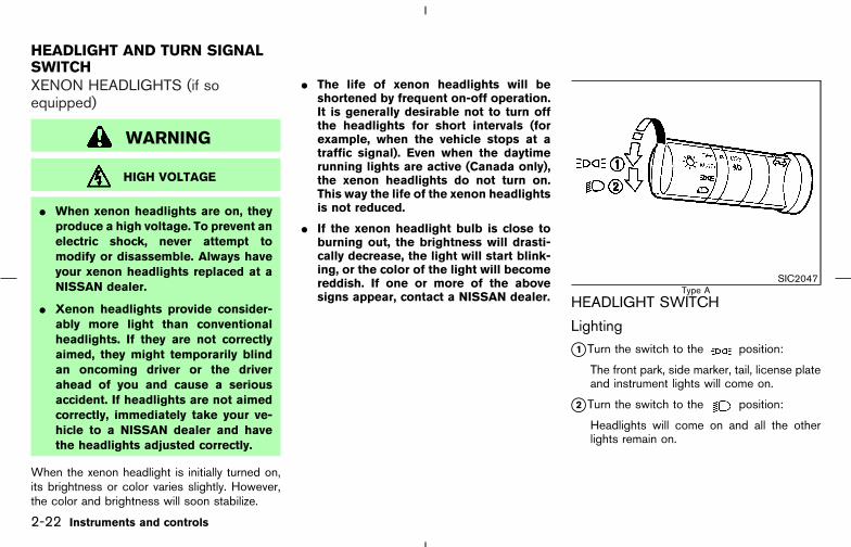
XENON HEADLIGHTS (if soequipped)
WARNING
HIGH VOLTAGE
� When xenon headlights are on, theyproduce a high voltage. To prevent anelectric shock, never attempt tomodify or disassemble. Always haveyour xenon headlights replaced at aNISSAN dealer.
� Xenon headlights provide consider-ably more light than conventionalheadlights. If they are not correctlyaimed, they might temporarily blindan oncoming driver or the driverahead of you and cause a seriousaccident. If headlights are not aimedcorrectly, immediately take your ve-hicle to a NISSAN dealer and havethe headlights adjusted correctly.
When the xenon headlight is initially turned on,its brightness or color varies slightly. However,the color and brightness will soon stabilize.
� The life of xenon headlights will beshortened by frequent on-off operation.It is generally desirable not to turn offthe headlights for short intervals (forexample, when the vehicle stops at atraffic signal). Even when the daytimerunning lights are active (Canada only),the xenon headlights do not turn on.This way the life of the xenon headlightsis not reduced.
� If the xenon headlight bulb is close toburning out, the brightness will drasti-cally decrease, the light will start blink-ing, or the color of the light will becomereddish. If one or more of the abovesigns appear, contact a NISSAN dealer. HEADLIGHT SWITCH
Lighting
�1 Turn the switch to the position:
The front park, side marker, tail, license plateand instrument lights will come on.
�2 Turn the switch to the position:
Headlights will come on and all the otherlights remain on.
SIC2047Type A
HEADLIGHT AND TURN SIGNALSWITCH
2-22 Instruments and controls
� 04.8.3/Z50-D/V5.0 �

CAUTION
Use the headlights with the engine run-ning to avoid discharging the vehiclebattery.
Autolight system (if so equipped)
The autolight system allows the headlights to beset so they turn on and off automatically.
To set the autolight system:
1. Turn the headlight switch to the AUTO posi-tion.
2. Turn the ignition switch to ON.
3. The autolight system automatically turns theheadlights on and off.
To turn the autolight system off, turn the switchto the OFF, , or position.
The autolight system can turn on the headlightsautomatically when it is dark, turn off the head-lights when it is light, and keep the headlights onfor up to 45 seconds after you turn the ignitionswitch to the OFF position and open any doorthen close all the doors. The headlight off timecan be adjusted on the system setting display.See the “4. Display screen, heater, air condi-tioner and audio system” section.
If the ignition switch is turned OFF and one ofthe doors is opened and this condition is con-tinued, the headlights remain ON for 5 minutes.
SIC1961Type B
SIC2051
Instruments and controls 2-23
� 04.8.3/Z50-D/V5.0 �

Be sure not to put anything on top of thephoto sensor �A located on the top left-hand side of the instrument panel. Thephoto sensor controls the autolamp; if it iscovered, the photo sensor reacts as if it isdark and the headlights will illuminate.
Headlight beam select
�1 To select the low beam, put the lever in theneutral position as shown.
�2 To select the high beam, push the leverforward while the switch is in the po-sition. Pull it back to select the low beam.
�3 Pulling the lever toward you will flash theheadlight high beam.
Battery saver system� When the headlight switch is in the or
position while the ignition switch is inthe ON position, the lights will automaticallyturn off 5 minutes after the ignition switch hasbeen turned to the OFF position.
� When the headlight switch remains in theor position after the lights auto-
matically turn off, the lights will turn on for 5minutes when the headlight switch is turnedto the OFF position and then turn to the
or position.
CAUTION
Even though the battery saver featureautomatically turns off the headlightsafter a period of time, you should turnthe headlight switch to the OFF positionwhen the engine is not running to avoiddischarging the vehicle battery.
SIC2052 SIC2048
2-24 Instruments and controls
� 04.8.3/Z50-D/V5.0 �
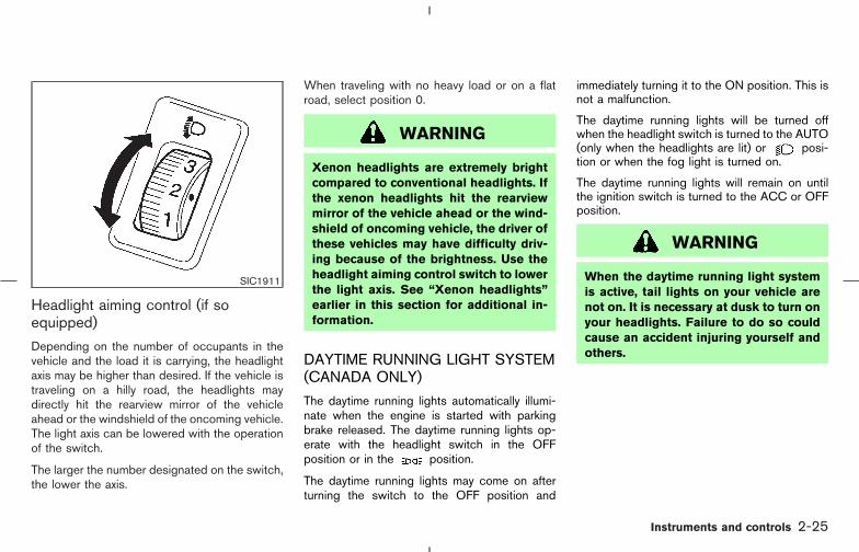
Headlight aiming control (if soequipped)
Depending on the number of occupants in thevehicle and the load it is carrying, the headlightaxis may be higher than desired. If the vehicle istraveling on a hilly road, the headlights maydirectly hit the rearview mirror of the vehicleahead or the windshield of the oncoming vehicle.The light axis can be lowered with the operationof the switch.
The larger the number designated on the switch,the lower the axis.
When traveling with no heavy load or on a flatroad, select position 0.
WARNING
Xenon headlights are extremely brightcompared to conventional headlights. Ifthe xenon headlights hit the rearviewmirror of the vehicle ahead or the wind-shield of oncoming vehicle, the driver ofthese vehicles may have difficulty driv-ing because of the brightness. Use theheadlight aiming control switch to lowerthe light axis. See “Xenon headlights”earlier in this section for additional in-formation.
DAYTIME RUNNING LIGHT SYSTEM(CANADA ONLY)
The daytime running lights automatically illumi-nate when the engine is started with parkingbrake released. The daytime running lights op-erate with the headlight switch in the OFFposition or in the position.
The daytime running lights may come on afterturning the switch to the OFF position and
immediately turning it to the ON position. This isnot a malfunction.
The daytime running lights will be turned offwhen the headlight switch is turned to the AUTO(only when the headlights are lit) or posi-tion or when the fog light is turned on.
The daytime running lights will remain on untilthe ignition switch is turned to the ACC or OFFposition.
WARNING
When the daytime running light systemis active, tail lights on your vehicle arenot on. It is necessary at dusk to turn onyour headlights. Failure to do so couldcause an accident injuring yourself andothers.
SIC1911
Instruments and controls 2-25
� 04.8.3/Z50-D/V5.0 �
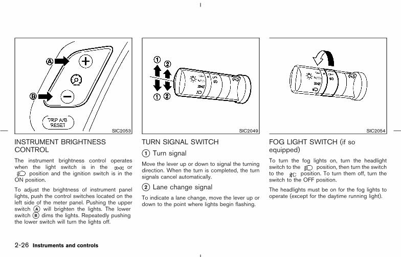
INSTRUMENT BRIGHTNESSCONTROLThe instrument brightness control operateswhen the light switch is in the or
position and the ignition switch is in theON position.
To adjust the brightness of instrument panellights, push the control switches located on theleft side of the meter panel. Pushing the upperswitch �A will brighten the lights. The lowerswitch �B dims the lights. Repeatedly pushingthe lower switch will turn the lights off.
TURN SIGNAL SWITCH
�1 Turn signalMove the lever up or down to signal the turningdirection. When the turn is completed, the turnsignals cancel automatically.
�2 Lane change signalTo indicate a lane change, move the lever up ordown to the point where lights begin flashing.
FOG LIGHT SWITCH (if soequipped)To turn the fog lights on, turn the headlightswitch to the position, then turn the switchto the position. To turn them off, turn theswitch to the OFF position.
The headlights must be on for the fog lights tooperate (except for the daytime running light).
SIC2053 SIC2049 SIC2054
2-26 Instruments and controls
� 04.8.3/Z50-D/V5.0 �
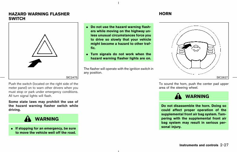
Push the switch (located on the right side of themeter panel) on to warn other drivers when youmust stop or park under emergency conditions.All turn signal lights will flash.
Some state laws may prohibit the use ofthe hazard warning flasher switch whiledriving.
WARNING
� If stopping for an emergency, be sureto move the vehicle well off the road.
� Do not use the hazard warning flash-ers while moving on the highway un-less unusual circumstances force youto drive so slowly that your vehiclemight become a hazard to other traf-fic.
� Turn signals do not work when thehazard warning flasher lights are on.
The flasher will operate with the ignition switch inany position.
To sound the horn, push the center pad upperarea of the steering wheel.
WARNING
Do not disassemble the horn. Doing socould affect proper operation of thesupplemental front air bag system. Tam-pering with the supplemental front airbag system may result in serious per-sonal injury.
SIC2475 SIC2627
HAZARD WARNING FLASHERSWITCH
HORN
Instruments and controls 2-27
� 04.8.3/Z50-D/V5.0 �
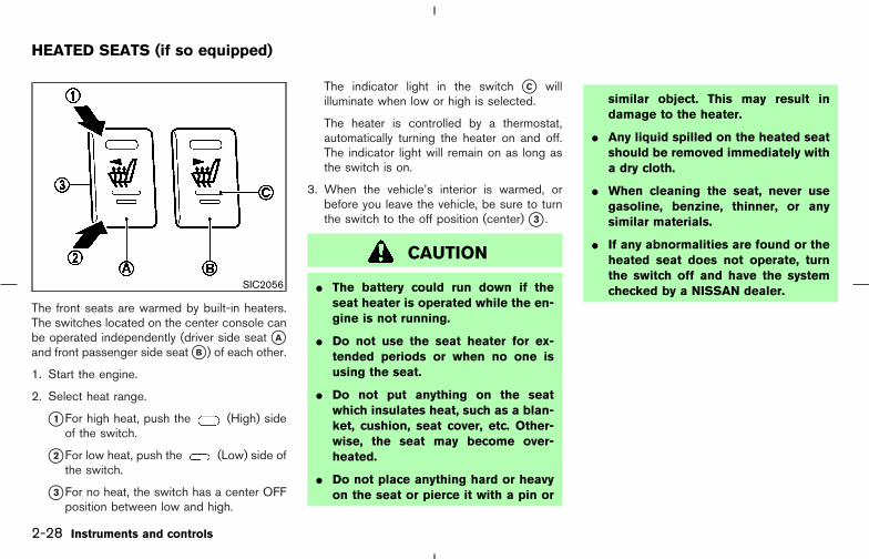
The front seats are warmed by built-in heaters.The switches located on the center console canbe operated independently (driver side seat �Aand front passenger side seat �B ) of each other.
1. Start the engine.
2. Select heat range.
�1 For high heat, push the (High) sideof the switch.
�2 For low heat, push the (Low) side ofthe switch.
�3 For no heat, the switch has a center OFFposition between low and high.
The indicator light in the switch �C willilluminate when low or high is selected.
The heater is controlled by a thermostat,automatically turning the heater on and off.The indicator light will remain on as long asthe switch is on.
3. When the vehicle’s interior is warmed, orbefore you leave the vehicle, be sure to turnthe switch to the off position (center) �3 .
CAUTION
� The battery could run down if theseat heater is operated while the en-gine is not running.
� Do not use the seat heater for ex-tended periods or when no one isusing the seat.
� Do not put anything on the seatwhich insulates heat, such as a blan-ket, cushion, seat cover, etc. Other-wise, the seat may become over-heated.
� Do not place anything hard or heavyon the seat or pierce it with a pin or
similar object. This may result indamage to the heater.
� Any liquid spilled on the heated seatshould be removed immediately witha dry cloth.
� When cleaning the seat, never usegasoline, benzine, thinner, or anysimilar materials.
� If any abnormalities are found or theheated seat does not operate, turnthe switch off and have the systemchecked by a NISSAN dealer.SIC2056
HEATED SEATS (if so equipped)
2-28 Instruments and controls
� 04.8.3/Z50-D/V5.0 �

The vehicle should be driven with the VehicleDynamic Control (VDC) system ON for mostdriving conditions.
If the vehicle is stuck in mud or snow, the VDCsystem reduces the engine output to reducewheel spin. The engine speed will be reducedeven if the accelerator is depressed to the floor.If maximum engine power is needed to free astuck vehicle, turn the VDC system off.
To turn off the Vehicle Dynamic Control (VDC)system, push the VDC OFF switch. The in-dicator light will come on.
Push the VDC OFF switch again or restart theengine to turn ON the system. See “Vehicle
dynamic control (VDC) system” in the “5. Start-ing and driving” section.
SIC1881
SIC2066
VEHICLE DYNAMIC CONTROL(VDC) OFF SWITCH (if soequipped)
POWER OUTLET
Instruments and controls 2-29
� 04.8.3/Z50-D/V5.0 �

The power outlet is for powering electrical ac-cessories such as cellular telephones.
�1 Located beside the glove box (if soequipped):Pull down the cover to open.
�2 Located inside the console box:Pull to remove the cover to open.
�3 Located the side of the luggage room (if soequipped):Pull up the cover to open.
CAUTION
� The outlet and plug may be hot dur-ing or immediately after use.
� This power outlet is not designed foruse with a cigarette lighter unit.
� Do not use with accessories that ex-ceed a 12 volt, 120W (10A) powerdraw. Do not use double adapters ormore than one electrical accessory.
� Use only one power outlet at a time.
� Use power outlet with the enginerunning to avoid discharging the ve-
hicle battery.
� Avoid using power outlets when theair conditioner, headlights or rearwindow defroster is on.
� Before inserting or disconnecting aplug, be sure to turn off the powerswitch of electrical accessory beingused or the ACC power of the vehicle.
� Push the plug in as far as it will go. Ifgood contact is not made, the plugmay overheat or the internal tem-perature fuse may open.
� When not in use, be sure to close thecap/cover. Do not allow water to con-tact the outlet.
COIN BOX
WARNING
The coin box should not be used whiledriving so full attention may be given tovehicle operation.
To open, push the coin box lid �1 as illustrated.
The inner tray can be removed �2 as illustrated.
Do not place valuable items in the box.
Do not use the coin box as an ashtray.
SIC2057
STORAGE
2-30 Instruments and controls
� 04.8.3/Z50-D/V5.0 �

CELLULAR PHONE HOLDER
WARNING
� The cellular phone holder should notbe used while driving so full attentionmay be given to vehicle operation.
� A cellular telephone should not beused while driving so full attentionmay be given to vehicle operation.Some jurisdictions prohibit the useof cellular telephones while driving.
� If a conversation in a moving vehiclerequires you to take notes, pull offthe road to a safe location and stopyour vehicle before doing so.
To open, push the cellular phone holder lid �1as illustrated.
The inner tray can be removed �2 as illustrated.
Do not place valuable items in the holder.
Do not use the cellular phone holder as anashtray.
CUP HOLDERS
WARNING
The cup holder should not be used whiledriving so full attention may be given tovehicle operation.
CAUTION
� Avoid abrupt starting and braking
SIC2058 SIC2628
Instruments and controls 2-31
� 04.8.3/Z50-D/V5.0 �
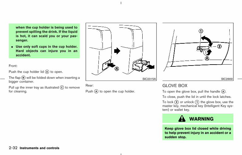
when the cup holder is being used toprevent spilling the drink. If the liquidis hot, it can scald you or your pas-senger.
� Use only soft cups in the cup holder.Hard objects can injure you in anaccident.
Front:
Push the cup holder lid �A to open.
The flap �B will be folded down when inserting abigger container.
Pull up the inner tray as illustrated �C to removefor cleaning.
Rear:
Push �A to open the cup holder.
GLOVE BOXTo open the glove box, pull the handle �A .
To close, push the lid in until the lock latches.
To lock �2 or unlock �1 the glove box, use themaster key, mechanical key (Intelligent Key sys-tem) or wallet key.
WARNING
Keep glove box lid closed while drivingto help prevent injury in an accident or asudden stop.
SIC2315A SIC2669
2-32 Instruments and controls
� 04.8.3/Z50-D/V5.0 �

CONSOLE BOX
WARNING
The center console box should not be
used while driving so full attention maybe given to vehicle operation.
Push the button �A to open the console box lid.
The inside of the console box lid is designed tobe used as a holder �B such as pen, etc. Thereis a power outlet �C inside the console box.
Remove the inside tray �D to store a largeobject.
To lock the console box, turn the key to the �1position.
To unlock the console box, turn the key to the �2position.
Push the button �3 and adjust the armrest to thedesired position.
SIC2208A
Instruments and controls 2-33
� 04.8.3/Z50-D/V5.0 �

CARGO NET (if so equipped)The cargo net helps keep packages in the cargoarea from moving around while your vehicle isdriven.
To install the cargo net, attach the hooks to theretainers �A on both sides.
To remove the cargo net, detach the hooks fromthe cargo net retainers.
For more retainers, refer to “Vehicle loadinginformation” in the “9. Technical and consumerinformation” section.
WARNING
� Properly secure all cargo to help pre-vent it from sliding or shifting.
� Be sure to secure all four hooks intothe retainers. The cargo restrained inthe net must not exceed 30 lbs (13.6kg) or the net may not stay secured.
TONNEAU COVER (if so equipped)
The tonneau cover keeps the luggage compart-ment contents hidden from the outside.
To open the tonneau cover, pull it out and hangboth sides on the hooks. To close the tonneaucover, remove it from the hooks and put the hook�A on the guide �B then release it as illustrated.
To open the sub cover �C , pull out and hangboth sides on the hooks behind the rear seathead restraint. To close the sub cover, remove itfrom the hooks and release it.
To remove the tonneau cover, pull the holder tothe opposite side �1 .
SIC2061 SIC2629
2-34 Instruments and controls
� 04.8.3/Z50-D/V5.0 �
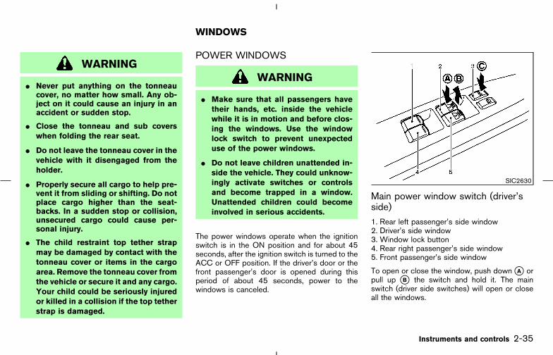
WARNING
� Never put anything on the tonneaucover, no matter how small. Any ob-ject on it could cause an injury in anaccident or sudden stop.
� Close the tonneau and sub coverswhen folding the rear seat.
� Do not leave the tonneau cover in thevehicle with it disengaged from theholder.
� Properly secure all cargo to help pre-vent it from sliding or shifting. Do notplace cargo higher than the seat-backs. In a sudden stop or collision,unsecured cargo could cause per-sonal injury.
� The child restraint top tether strapmay be damaged by contact with thetonneau cover or items in the cargoarea. Remove the tonneau cover fromthe vehicle or secure it and any cargo.Your child could be seriously injuredor killed in a collision if the top tetherstrap is damaged.
POWER WINDOWS
WARNING
� Make sure that all passengers havetheir hands, etc. inside the vehiclewhile it is in motion and before clos-ing the windows. Use the windowlock switch to prevent unexpecteduse of the power windows.
� Do not leave children unattended in-side the vehicle. They could unknow-ingly activate switches or controlsand become trapped in a window.Unattended children could becomeinvolved in serious accidents.
The power windows operate when the ignitionswitch is in the ON position and for about 45seconds, after the ignition switch is turned to theACC or OFF position. If the driver’s door or thefront passenger’s door is opened during thisperiod of about 45 seconds, power to thewindows is canceled.
Main power window switch (driver’sside)1. Rear left passenger’s side window2. Driver’s side window3. Window lock button4. Rear right passenger’s side window5. Front passenger’s side window
To open or close the window, push down �A orpull up �B the switch and hold it. The mainswitch (driver side switches) will open or closeall the windows.
SIC2630
WINDOWS
Instruments and controls 2-35
� 04.8.3/Z50-D/V5.0 �

Locking passenger’s windowsWhen the lock button �C is pushed in, only thedriver side window can be opened or closed.Push it in again to cancel.
Passenger side power window switchThe passenger side switch will open or closeonly the corresponding window. To open orclose the window, hold the switch down �A orup �B .
Automatic operation
To fully open or close the driver’s or frontpassenger’s side window, completely pushdown �A or pull up �B the switch and release it;it need not be held. The window will automati-cally open or close all the way. To stop thewindow, just push or lift the switch on theopposite side.
Auto reverse function (For frontwindow)If the control unit detects something caught in afront window as it moves up, the window will beimmediately lowered.
SIC1892F SIC1893E
2-36 Instruments and controls
� 04.8.3/Z50-D/V5.0 �
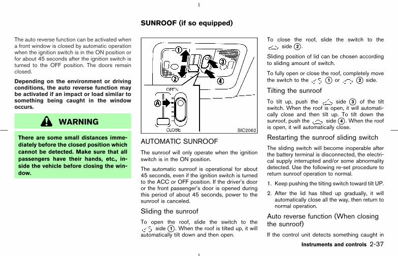
The auto reverse function can be activated whena front window is closed by automatic operationwhen the ignition switch is in the ON position orfor about 45 seconds after the ignition switch isturned to the OFF position. The doors remainclosed.
Depending on the environment or drivingconditions, the auto reverse function maybe activated if an impact or load similar tosomething being caught in the windowoccurs.
WARNING
There are some small distances imme-diately before the closed position whichcannot be detected. Make sure that allpassengers have their hands, etc., in-side the vehicle before closing the win-dow.
AUTOMATIC SUNROOF
The sunroof will only operate when the ignitionswitch is in the ON position.
The automatic sunroof is operational for about45 seconds, even if the ignition switch is turnedto the ACC or OFF position. If the driver’s dooror the front passenger’s door is opened duringthis period of about 45 seconds, power to thesunroof is canceled.
Sliding the sunroofTo open the roof, slide the switch to the
side �1 . When the roof is tilted up, it willautomatically tilt down and then open.
To close the roof, slide the switch to theside �2 .
Sliding position of lid can be chosen accordingto sliding amount of switch.
To fully open or close the roof, completely movethe switch to the �1 or �2 side.
Tilting the sunroof
To tilt up, push the side �3 of the tiltswitch. When the roof is open, it will automati-cally close and then tilt up. To tilt down thesunroof, push the side �4 . When the roofis open, it will automatically close.
Restarting the sunroof sliding switchThe sliding switch will become inoperable afterthe battery terminal is disconnected, the electri-cal supply interrupted and/or some abnormalitydetected. Use the following re-set procedure toreturn sunroof operation to normal.
1. Keep pushing the tilting switch toward tilt UP.
2. After the lid has tilted up gradually, it willautomatically close all the way, then return tonormal operation.
Auto reverse function (When closingthe sunroof)If the control unit detects something caught in
SIC2062
SUNROOF (if so equipped)
Instruments and controls 2-37
� 04.8.3/Z50-D/V5.0 �
the sunroof as it moves to the front or tilts down,the sunroof will immediately open backward ortilt up.
The auto reverse function can be activated whenthe sunroof is closed by automatic operationwhen the ignition switch is in the ON position orfor about 45 seconds after the ignition switch isturned to the OFF position.
Depending on the environment or drivingconditions, the auto reverse function maybe activated if an impact or load similar tosomething being caught in the sunroofoccurs.
If the auto reverse function malfunctions andrepeats opening or tilting up the sunroof, keeppushing toward the close position or keep push-ing the tilt down switch within 5 seconds after ithappens, then the sunroof will fully close gradu-ally. In this case, make sure nothing is caught inthe sunroof.
WARNING
There are some small distances imme-diately before the closed position whichcannot be detected. Make sure that allpassengers have their hands, etc., in-
side the vehicle before closing thesunroof.
Sun shade
Open or close the sun shade by sliding itbackward or forward.
The shade will open automatically when thesunroof is opened. However, it must be closedmanually.
Comfortable position ( �A )
Depending on the driving speed and air recircu-lating conditions, wind noise may occur whenthe sunroof is fully opened. Closing the sunroofone step toward the front position �A from fullopen will decrease the wind noise.
WARNING
� In an accident you could be thrownfrom the vehicle through an opensunroof. Always use seat belts andchild restraints.
� Do not allow anyone to stand up orextend any portion of their body out
of the sunroof opening while the ve-hicle is in motion or while the sun-roof is closing.
CAUTION
� Remove water drops, snow, ice orsand from the sunroof before open-ing.
� Do not place any heavy object on thesunroof or surrounding area.
If the sunroof does not closeHave a NISSAN dealer check and repair thesunroof.
2-38 Instruments and controls
� 04.8.3/Z50-D/V5.0 �

CEILING LIGHT
The ceiling light has a three-position switch.
When the switch is in the ON position �1 , thelight will illuminate.
When the switch is in the OFF position �2 , thelight will turn off.
When the switch is in the DOOR position �3 ,the light will illuminate when a door is opened.
The light will stay on for about 30 seconds when:
� The doors are unlocked by the remote key-less entry system, a key, power door lockswitch or using the Intelligent Key system
while all doors are closed.
� The driver’s door is opened and then closedwhile the key is removed from the ignitionswitch or the ignition switch is turned to theLOCK position (Intelligent Key system).
� The key is removed from the ignition switch orthe ignition switch is turned to the LOCKposition (Intelligent Key system) while alldoors are closed.
The ceiling light will turn off while the 30 secondtimer is activated, when:
� The driver’s door is locked by the remotekeyless entry system, a key or the power doorlock switch.
� The ignition switch is turned ON.
When the ceiling light switch or map lightswitch or rear personal light switch is in theON position, the ceiling, map, rear andvanity mirror lights will automatically turnoff 30 minutes after the ignition switch hasbeen turned to the ACC or OFF position. Toturn on the light again, turn the ignitionswitch to the ON position.
After the above procedure, the ceiling, map, rearpersonal and vanity mirror lights will automati-cally turn off 30 minutes after the latest operation
of the following with the ignition switch in theACC or OFF position:
� Opening or closing any door
� Locking or unlocking with the remote keylessentry system, a key, the lock-unlock switch orthe ignition switch is turned to the LOCKposition (Intelligent Key system).
� Inserting or removing a key from the ignitionswitch
These lights will turn on again when any of theabove operations is performed after the lightshave turned off automatically. (The lights will turnoff 30 minutes after the latest operation of theabove as well.)
CAUTION
� Turn off the ceiling, map, rear andvanity mirror lights when you leavethe vehicle.
� Do not use for extended periods oftime with the engine stopped. Thiscould result in a discharged battery.
SIC2063
INTERIOR LIGHTS
Instruments and controls 2-39
� 04.8.3/Z50-D/V5.0 �

MAP LIGHTTo turn on the light, push the plastic surface �Aof the light. Push it again to turn off the light.
REAR PERSONAL LIGHT
The rear personal light has a three-positionswitch. (�A : DOOR, �B : OFF, �C : ON)
When the switch is in the DOOR position �A ,the light will illuminate when a door is opened.
When the ceiling light or the map lightswitch or rear personal light switch is in theON position �C , the ceiling, map, rear per-sonal and vanity mirror lights will auto-matically turn off 30 minutes after the ig-nition switch has been turned to the OFFposition �B . To turn on the light again, turnthe ignition switch to the ON position.
CAUTION
� Turn off the ceiling, map, rear andvanity mirror lights when you leavethe vehicle.
� Do not use for extended periods oftime with the engine stopped. Thiscould result in a discharged battery.
SIC2068Front
SIC2069Rear
2-40 Instruments and controls
� 04.8.3/Z50-D/V5.0 �

LUGGAGE LIGHTWhen the switch is in the ON position �A , thelight illuminates while the back door is opened.When the back door is closed, the light will gooff.
When the switch is in the OFF position �B , thelight will turn off.
The light on the vanity mirror will turn on whenthe cover on the vanity mirror is opened.
When the ceiling light or the map lightswitch or rear personal light switch is in theON position, the ceiling, map, rear per-sonal and vanity mirror lights will auto-matically turn off 30 minutes after the ig-nition switch has been turned to the OFFposition. To turn on the light again, turn theignition switch to the ON position.
The HomeLink Universal Transceiver provides aconvenient way to consolidate the functions ofup to three individual hand-held transmitters intoone built-in device.
HomeLink Universal Transceiver:
� Will operate most Radio Frequency (RF)devices such as garage doors, gates, homeand office lighting, entry door locks and se-curity systems.
� Is powered by your vehicle’s battery. Noseparate batteries are required. If the vehi-cle’s battery is discharged or is discon-nected, HomeLink will retain all program-ming.
Once the HomeLink Universal Transceiveris programmed, retain the original trans-mitter for future programming procedures(Example: new vehicle purchases). Uponsale of the vehicle, the programmedHomeLink Universal Transceiver buttonsshould be erased for security purposes.For additional information, refer to “Pro-gramming HomeLink ” later in this sec-tion.
SIC2131 SIC2064
VANITY MIRROR LIGHT (if soequipped)
HomeLink UNIVERSALTRANSCEIVER (if so equipped)
Instruments and controls 2-41
� 04.8.3/Z50-D/V5.0 �

WARNING
� Do not use the HomeLink UniversalTransceiver with any garage dooropener that lacks safety stop andreverse features as required by fed-eral safety standards. (These stan-dards became effective for openermodels manufactured after April 1,1982). A garage door opener whichcannot detect an object in the path ofa closing garage door and then auto-matically stop and reverse, does notmeet current federal safety stan-dards. Using a garage door openerwithout these features increases therisk of serious injury or death.
� During programming procedure, yourgarage door or security gate mayopen or close. Make sure that peopleand objects are clear of the garagedoor, gate, etc. that you are program-ming.
� Your vehicle’s engine should beturned off while programming the
HomeLink Universal Transceiver.PROGRAMMING HomeLinkTo program your HomeLink Transceiver to op-erate a garage door, gate, or entry door opener,home or office lighting, you need to be at thesame location as the device. Note: Garage dooropeners (manufactured after 1996) have “rollingcode protection”. To program a garage dooropener equipped with “rolling code protection”;you will need to use a ladder to get up to thegarage door opener motor to be able to accessthe “smart or learn” program button.
2-42 Instruments and controls
� 04.8.3/Z50-D/V5.0 �

1. To begin, push and hold the 2 outerHomeLink buttons (to clear the memory)until the indicator light �A blinks (after 20seconds). Release both buttons.
2. Position the end of the hand-held transmitter1-3 inches away from the HomeLink sur-face.
3. Using both hands, simultaneously push andhold both the HomeLink button you want toprogram and the hand-held transmitter but-ton.DO NOT release the buttons until step 4 hasbeen completed.
4. Hold down both buttons until the indicatorlight on the HomeLink flashes, changingfrom a “slow blink” to a “rapid blink”. Thiscould take up to 90 seconds. When theindicator light blinks rapidly, both buttonsmay be released. The rapidly flashing lightindicates successful programming. To acti-vate the garage door or other programmeddevice, push and hold the programmed
HomeLink button - releasing when the de-vice begins to activate.
5. If the indicator light on the HomeLink blinksrapidly for two seconds and then turns solid,HomeLink has picked up a “rolling code”garage door opener signal. You will need toproceed with the next steps to train theHomeLink to complete the programmingwhich may require a ladder and anotherperson for convenience.
6. Push and release the training button locatedon the garage door opener’s motor to acti-vate the “training mode”. This button is usu-ally located near the antenna wire that hangsdown from the motor. If the wire originatesfrom under a light lens, you will need toremove the lens to access the training button.
NOTE:
Once you have pushed and released thetraining button on the garage door open-er’s motor and the “training light” is lit, youhave 30 seconds in which to perform step7. Use the help of a second person forconvenience to assist when performingthis step.
7. Quickly within 30 seconds of pushing andreleasing the garage door opener trainingbutton, firmly push and release the
SIC2071C SIC2072
Instruments and controls 2-43
� 04.8.3/Z50-D/V5.0 �
HomeLink button you’ve just programmed.Push and release the HomeLink button upto three times to complete the training.
8. Your HomeLink button should now be pro-grammed. (To program the remainingHomeLink buttons for additional door orgate openers, follow steps 2 through 8 only.)
NOTE:
Do not repeat step one unless you want to“clear” all previously programmedHomeLink buttons).
If you have any questions or are having difficultyprogramming your HomeLink buttons, pleaserefer to the HomeLink web site at:www.homelink.com or call 1-800-355-3515.
PROGRAMMING HomeLink FORCANADIAN CUSTOMERS
Prior to 1992, D.O.C. regulations required hand-held transmitters to stop transmitting after 2seconds. To program your hand-held transmitterto HomeLink , continue to push and hold theHomeLink button (note steps 2 through 4under “Programming HomeLink ”) while youpush and re-push (“cycle”) your hand-heldtransmitter every 2 seconds until the indicatorlight flashes rapidly (indicating successful pro-gramming).
NOTE:
If programming a garage door opener, etc.,it is advised to unplug the device duringthe “cycling” process to prevent possibledamage to the garage door opener compo-nents.
OPERATING THE HomeLinkUNIVERSAL TRANSCEIVERThe HomeLink Universal Transceiver (onceprogrammed) may now be used to activate thegarage door, etc. To operate, simply push theappropriate programmed HomeLink UniversalTransceiver button. The red indicator light willilluminate while the signal is being transmitted.
PROGRAMMING TROUBLEDIAGNOSISIf the HomeLink does not quickly learn thehand-held transmitter information:
� replace the hand-held transmitter batterieswith new batteries.
� position the hand-held transmitter with itsbattery area facing away from the HomeLinksurface.
� push and hold both the HomeLink andhand-held transmitter buttons without inter-ruption.
� position the hand-held transmitter 2 to 5inches (50 to 127 mm) away from theHomeLink surface. Hold the transmitter inthat position for up to 15 seconds. IfHomeLink is not programmed within thattime, try holding the transmitter in anotherposition - keeping the indicator light in view atall times.
If you continue to have programming difficulties,please contact the NISSAN Consumer AffairsDepartment. The phone numbers are located inthe Foreword of this Owner’s Manual.
CLEARING THE PROGRAMMEDINFORMATIONIndividual buttons cannot be cleared, however toclear all programming, push and hold the twooutside buttons and release when the indicatorlight begins to flash (approximately 20 seconds).
2-44 Instruments and controls
� 04.8.3/Z50-D/V5.0 �
REPROGRAMMING A SINGLEHomeLink BUTTON
To reprogram a HomeLink Universal Trans-ceiver button, complete the following.
1. Push and hold the desired HomeLink but-ton. Do not release the button until step 4has been completed.
2. When the indicator light begins to flashslowly (after 20 seconds), position the hand-held transmitter 2 to 5 inches (50 to 127 mm)away from the HomeLink surface.
3. Push and hold the hand-held transmitter but-ton.
4. The HomeLink indicator light will flash, firstslowly and then rapidly. When the indicatorlight begins to flash rapidly, release bothbuttons.
The HomeLink Universal Transceiver buttonhas now been reprogrammed. The new devicecan be activated by pushing the HomeLinkbutton that was just programmed. This proce-dure will not affect any other programmedHomeLink buttons.
IF YOUR VEHICLE IS STOLENIf your vehicle is stolen, you should change thecodes of any non-rolling code device that has
been programmed into HomeLink . Consult theOwner’s Manual of each device or call themanufacturer or dealer of those devices foradditional information.
When your vehicle is recovered, you willneed to reprogram the HomeLink Univer-sal Transceiver with your new transmitterinformation.
FCC Notice:
This device complies with FCC rules part15. Operation is subject to the followingtwo conditions: (1) This device may notcause harmful interference and (2) Thisdevice must accept any interference thatmay be received, including interferencethat may cause undesired operation.
The transmitter has been tested and com-plies with FCC and DOC/MDC rules.Changes or modifications not expresslyapproved by the party responsible for com-pliance could void the user’s authority tooperate the device.
DOC: ISTC 1763K1313
FCC I.D.: CB2V67690
Instruments and controls 2-45
� 04.8.3/Z50-D/V5.0 �

MEMO
2-46 Instruments and controls
� 04.8.3/Z50-D/V5.0 �
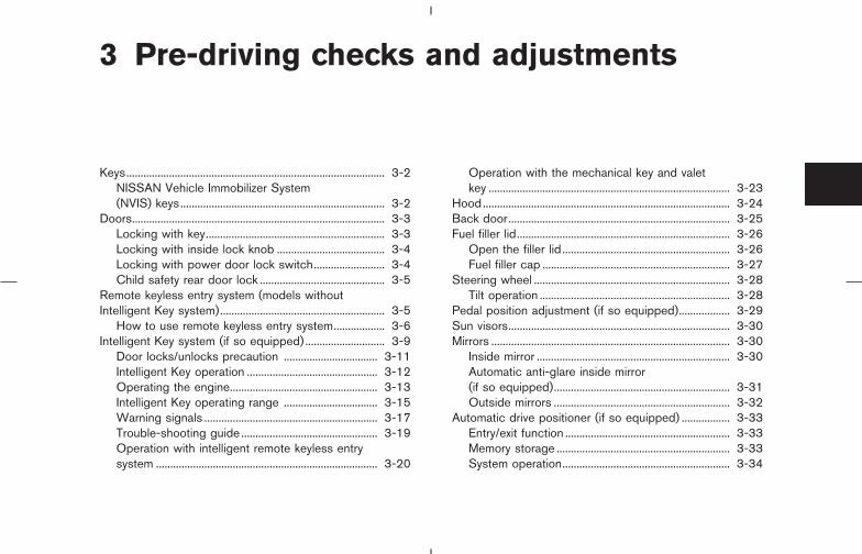
3 Pre-driving checks and adjustments
Keys........................................................................................... 3-2NISSAN Vehicle Immobilizer System(NVIS) keys........................................................................ 3-2
Doors......................................................................................... 3-3Locking with key............................................................... 3-3Locking with inside lock knob ...................................... 3-4Locking with power door lock switch......................... 3-4Child safety rear door lock ............................................ 3-5
Remote keyless entry system (models withoutIntelligent Key system).......................................................... 3-5
How to use remote keyless entry system.................. 3-6Intelligent Key system (if so equipped) ............................ 3-9
Door locks/unlocks precaution ................................. 3-11Intelligent Key operation .............................................. 3-12Operating the engine.................................................... 3-13Intelligent Key operating range ................................. 3-15Warning signals ............................................................. 3-17Trouble-shooting guide ................................................ 3-19Operation with intelligent remote keyless entrysystem .............................................................................. 3-20
Operation with the mechanical key and valetkey ..................................................................................... 3-23
Hood....................................................................................... 3-24Back door.............................................................................. 3-25Fuel filler lid........................................................................... 3-26
Open the filler lid ........................................................... 3-26Fuel filler cap .................................................................. 3-27
Steering wheel ..................................................................... 3-28Tilt operation ................................................................... 3-28
Pedal position adjustment (if so equipped).................. 3-29Sun visors.............................................................................. 3-30Mirrors .................................................................................... 3-30
Inside mirror .................................................................... 3-30Automatic anti-glare inside mirror(if so equipped).............................................................. 3-31Outside mirrors .............................................................. 3-32
Automatic drive positioner (if so equipped) ................. 3-33Entry/exit function .......................................................... 3-33Memory storage ............................................................. 3-33System operation........................................................... 3-34
� 04.8.3/Z50-D/V5.0 �
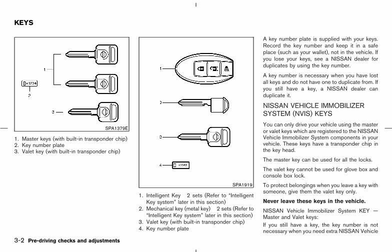
1. Master keys (with built-in transponder chip)2. Key number plate3. Valet key (with built-in transponder chip)
1. Intelligent Key 2 sets (Refer to “IntelligentKey system” later in this section)
2. Mechanical key (metal key) 2 sets (Refer to“Intelligent Key system” later in this section)
3. Valet key (with built-in transponder chip)4. Key number plate
A key number plate is supplied with your keys.Record the key number and keep it in a safeplace (such as your wallet), not in the vehicle. Ifyou lose your keys, see a NISSAN dealer forduplicates by using the key number.
A key number is necessary when you have lostall keys and do not have one to duplicate from. Ifyou still have a key, a NISSAN dealer canduplicate it.
NISSAN VEHICLE IMMOBILIZERSYSTEM (NVIS) KEYS
You can only drive your vehicle using the masteror valet keys which are registered to the NISSANVehicle Immobilizer System components in yourvehicle. These keys have a transponder chip inthe key head.
The master key can be used for all the locks.
The valet key cannot be used for glove box andconsole box lock.
To protect belongings when you leave a key withsomeone, give them the valet key only.
Never leave these keys in the vehicle.
NISSAN Vehicle Immobilizer System KEY —Master and Valet keys:If you still have a key, the key number is notnecessary when you need extra NISSAN Vehicle
SPA1379E
SPA1919
KEYS
3-2 Pre-driving checks and adjustments
� 04.8.3/Z50-D/V5.0 �

Immobilizer System keys. A NISSAN dealer canduplicate it. As many as 5 NVIS keys can beused with one vehicle. You should bring all NVISkeys that you have to a NISSAN dealer forregistration. This is because the registrationprocess will erase the memory of all key codespreviously registered into the NISSAN VehicleImmobilizer System. After the registration pro-cess, these components will only recognize keyscoded into the NISSAN Vehicle ImmobilizerSystem (NVIS) during registration. Any key thatis not given to your dealer at the time of regis-tration will no longer be able to start your vehicle.
Do not allow the immobilizer system key,which contains an electrical transponder,to come into contact with salt water. Thiscould affect system function.
WARNING
� Always have the doors locked whiledriving. Along with the use of seatbelts, this provides greater safety inthe event of an accident by helping toprevent persons from being thrownfrom the vehicle. This also helps keepchildren and others from uninten-tionally opening the doors, and willhelp keep out intruders.
� Before opening any door, alwayslook for and avoid oncoming traffic.
� Do not leave children unattended in-side the vehicle. They could unknow-ingly activate switches or controls.Unattended children could becomeinvolved in serious accidents.
LOCKING WITH KEY
Power
The power door lock system allows you to lockor unlock all doors simultaneously.
� Turning the driver’s door key to the front ofthe vehicle �1 will lock all doors (includingthe back door) and fuel filler lid.
� Turning the driver’s door key one time to therear of the vehicle �2 will unlock the driver’sdoor. From that position, returning the key toneutral (where the key can only be removedand inserted) and turning it to the rear againwithin 5 seconds will unlock all doors and fuel
SPA1575A
DOORS
Pre-driving checks and adjustments 3-3
� 04.8.3/Z50-D/V5.0 �

filler lid. Unlock simulation can be changed.See the “4. Display screen, heater, air condi-tioner and audio system” section.
Opening and closing front windowsTurn the driver’s door key to the unlock positionand hold for about 1 second, the front windowswill begin to lower.
To stop opening, turn the key to the neutralposition.
To close the front windows with the door keycylinder, turn the key to the lock position andhold for about 1 second.
To stop closing, turn the key to the neutralposition.
In the event of a hand in the way, or otherobstruction, the auto reverse function will acti-vate.
LOCKING WITH INSIDE LOCKKNOBTo individually lock the doors, move the insidelock knob to the LOCK position �1 , then closethe door.
To unlock, move the inside lock knob up to theUNLOCK position �2 .
When locking the door without a key, besure not to leave the key inside the vehicle.
LOCKING WITH POWER DOORLOCK SWITCHOperating the lock-unlock switch will lock orunlock all doors. (driver and front passengersides)
To lock the doors, push the power door lockswitch located on the driver’s �1 or front pas-senger’s �2 armrest to the lock position �A withthe driver’s or front passenger’s door open, thenclose the door.
When locking the door this way, be certainnot to leave the key inside the vehicle.
SPA1814 SPA1576A
3-4 Pre-driving checks and adjustments
� 04.8.3/Z50-D/V5.0 �

To unlock, push the power door lock switch tothe unlock position �B .
Lockout protectionWhen the power door lock switch (driver or frontpassenger) is moved to the LOCK position withthe key in the ignition and any door open, alldoors will lock and unlock automatically. Thishelps to prevent the keys from being accidentallylocked inside the vehicle.
CHILD SAFETY REAR DOOR LOCKChild safety locking helps prevent doors frombeing opened accidentally, especially whensmall children are in the vehicle.
When the lever is in the LOCK position �1 ,the rear door can be opened only from theoutside.
To disengage, move the lever to the FREEposition �2 .
It is possible to lock/unlock all doors (includingthe back door) and fuel filler lid and activate thepanic alarm by using the keyfob from outside thevehicle.Before locking the doors, make sure thekey is not left in the vehicle.The keyfob can operate at a distance of approxi-mately 33 ft (10 m) from the vehicle. (Theeffective distance depends upon the conditionsaround the vehicle.)As many as five keyfobs can be used with onevehicle. For information concerning the purchaseand use of additional keyfobs, contact a NISSANdealer.
The keyfob will not function when:
� the battery is discharged,
� the distance between the vehicle and thekeyfob is over 33 ft (10 m).
The panic alarm will not activate when thekey is in the ignition switch.
CAUTION
The following conditions or occurrenceswill damage the keyfob.
SPA1577A
REMOTE KEYLESS ENTRYSYSTEM (models withoutIntelligent Key system)
Pre-driving checks and adjustments 3-5
� 04.8.3/Z50-D/V5.0 �

� Do not allow the keyfob to becomewet.
� Do not drop the keyfob.
� Do not strike the keyfob sharplyagainst another object.
� Do not place the keyfob for an ex-tended period in an area where tem-peratures exceed 140°F (60°C).
If a keyfob is lost or stolen, NISSANrecommends erasing the ID code of thatkeyfob. This will prevent the keyfobfrom unauthorized use to unlock thevehicle. For information regarding theerasing procedure, please contact aNISSAN dealer.
HOW TO USE REMOTE KEYLESSENTRY SYSTEM
Setting hazard indicator and hornmode
The factory setting of the remote keyless entrysystem is in hazard indicator and horn mode.
In hazard indicator and horn mode, when the
LOCK button is pushed, the hazard indicatorflashes twice and the horn chirps once. Whenthe UNLOCK button is pushed, the hazard indi-cator flashes once.
If hazard indicator and horn mode is not neces-sary, you can switch to hazard indicator onlymode by following the switching procedure.
In hazard indicator only mode, when the LOCKbutton is pushed, the hazard indicator flashestwice. When the UNLOCK button is pushed,neither the hazard indicator nor the horn oper-ates.
3-6 Pre-driving checks and adjustments
� 04.8.3/Z50-D/V5.0 �

(Switching procedure)
Push the LOCK and UNLOCK buttons on thekeyfob simultaneously for more than 2 secondsto switch from one mode to the other.
When pushing the buttons to set hazard indica-tor only mode, the hazard indicator flashes 3times.
When pushing the buttons to set hazard indica-tor and horn mode, the hazard indicator flashesonce and the horn chirps once.
Locking doors and fuel filler lid
1. Remove the ignition key.*1
2. Close all the doors and fuel filler lid.*2
3. Push the LOCK button �A on the keyfob.
4. All the doors and fuel filler lid will lock.
All of the doors will lock when the LOCKbutton on the keyfob is pushed eventhough a door remains open and/or theignition switch is in the ON position.
5. The hazard indicator flashes twice and thehorn chirps once.
SPA1260 SPA1397C
Pre-driving checks and adjustments 3-7
� 04.8.3/Z50-D/V5.0 �
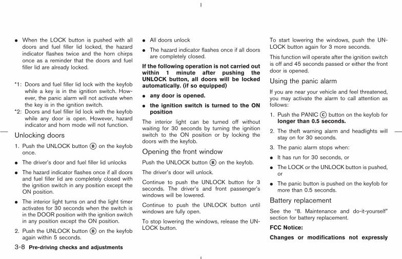
� When the LOCK button is pushed with alldoors and fuel filler lid locked, the hazardindicator flashes twice and the horn chirpsonce as a reminder that the doors and fuelfiller lid are already locked.
*1: Doors and fuel filler lid lock with the keyfobwhile a key is in the ignition switch. How-ever, the panic alarm will not activate whenthe key is in the ignition switch.
*2: Doors and fuel filler lid lock with the keyfobwhile any door is open. However, hazardindicator and horn mode will not function.
Unlocking doors1. Push the UNLOCK button �B on the keyfob
once.
� The driver’s door and fuel filler lid unlocks
� The hazard indicator flashes once if all doorsand fuel filler lid are completely closed withthe ignition switch in any position except theON position.
� The interior light turns on and the light timeractivates for 30 seconds when the switch isin the DOOR position with the ignition switchin any position except the ON position.
2. Push the UNLOCK button �B on the keyfobagain within 5 seconds.
� All doors unlock
� The hazard indicator flashes once if all doorsare completely closed.
If the following operation is not carried outwithin 1 minute after pushing theUNLOCK button, all doors will be lockedautomatically. (if so equipped)
� any door is opened.
� the ignition switch is turned to the ONposition
The interior light can be turned off withoutwaiting for 30 seconds by turning the ignitionswitch to the ON position or by locking thedoors with the keyfob.
Opening the front windowPush the UNLOCK button �B on the keyfob.
The driver’s door will unlock.
Continue to push the UNLOCK button for 3seconds. The driver’s and front passenger’swindows will be lowered.
Continue to push the UNLOCK button untilwindows are fully open.
To stop lowering the windows, release the UN-LOCK button.
To start lowering the windows, push the UN-LOCK button again for 3 more seconds.
This function will operate after the ignition switchis off and 45 seconds passed or either the frontdoor is opened.
Using the panic alarmIf you are near your vehicle and feel threatened,you may activate the alarm to call attention asfollows:
1. Push the PANIC �C button on the keyfob forlonger than 0.5 seconds.
2. The theft warning alarm and headlights willstay on for 30 seconds.
3. The panic alarm stops when:
� It has run for 30 seconds, or
� The LOCK or the UNLOCK button is pushed,or
� The panic button is pushed on the keyfob formore than 0.5 seconds.
Battery replacementSee the “8. Maintenance and do-it-yourself”section for battery replacement.
FCC Notice:
Changes or modifications not expressly
3-8 Pre-driving checks and adjustments
� 04.8.3/Z50-D/V5.0 �

approved by the manufacturer compliancecould void the user’s authority to operatethe equipment. This device complies withPart 15 of the FCC Rules and RSS-210 ofIndustry Canada. Operation is subject tothe following two conditions: (1) This de-vice may not cause harmful interference,and (2) this device must accept any inter-ference received, including interferencethat may cause undesired operation of thedevice.
The Intelligent Key uses coded radio signals tocommunicate with the vehicle. When the Intelli-gent Key is near the vehicle, such as whenstanding near the vehicle with the Intelligent Keyin your pocket or purse, it allows the vehicle tobe locked or unlocked. And, when you are insidethe vehicle while carrying the Intelligent Key withyou, it allows the engine to be started withoutinserting the key to the ignition switch. It is alsopossible to use the remote keyless entry func-tion.
CAUTION
� Be sure to carry the Intelligent Keywith you.
� Do not leave the vehicle with theIntelligent Key inside.
� The Intelligent Key may not functioncorrectly depending on the environmentor operating conditions. It could alsomalfunction if you do not use it cor-rectly.
� The Intelligent Key transmits faint radiowaves.
In the following situations, the Intelli-gent Key and remote keyless entry func-
tions may not operate correctly, and youmay have to use the metal key (me-chanical key or valet key):
• when there are strong signals com-ing from a television tower, powerstation or broadcasting station.
• when you have wireless equipmentor a cellular phone with you.
• when the Intelligent Key is in contactwith or covered by a metallic mate-rial.
• when radio wave-type remote controlentry is used nearby.
• when the Intelligent Key is placednear an electric appliance such as apersonal computer.
� The Intelligent Key continually con-sumes battery power as the key receivesa signal to communicate with the ve-hicle. Battery life of the Intelligent Key isabout 2 years, although it varies de-pending on the operating conditions.When the battery of the Intelligent Keyis low, the green blinking key warninglight goes out about 30 seconds afterthe ignition switch is turned to ON. If thebattery runs down, replace it with a newone.
INTELLIGENT KEY SYSTEM (if soequipped)
Pre-driving checks and adjustments 3-9
� 04.8.3/Z50-D/V5.0 �

� If the Intelligent Key receives strongsignal over an extended period of time,the battery of the Intelligent Key couldquickly run down. Do not place the In-telligent Key near an electric appliancesuch as a television set or personalcomputer.
� Because the ignition switch is electroni-cally controlled, if the vehicle battery iscompletely discharged when the igni-tion switch is in the LOCK position, thesteering lock cannot be released or theignition switch cannot be turned (not bythe mechanical key either).
� In case the vehicle battery is completelydischarged, make sure to recharge thevehicle battery immediately.
1. Intelligent Key 2 sets2. Mechanical key (metal key)*1*2 2 sets3. Valet key (with built-in transponder chip)*14. Key number plate*1 The mechanical key and valet key are
equipped with Nissan Vehicle Immobilizer
System. Refer to “Nissan Vehicle ImmobilizerSystem (NVIS) keys” earlier in this section.
*2 Mechanical key is included in the IntelligentKey. Refer to “Operation with the mechanicalkey” later in this section for how to removethe mechanical key from the Intelligent Key.
WARNING
� The Intelligent Key transmits radiowaves that can adversely affect medi-cal electric equipment.
� If you have a pacemaker, you shouldcontact the medical equipmentmanufacturer to ask if it will be af-fected by the Intelligent Key signal.
Record the key number on the key numberplate/metal tag and keep it in a safe place (suchas your wallet), NOT IN THE VEHICLE. A keynumber plate is supplied with your key. Keep theplate in a safe place. NISSAN does not recordkey numbers so it is very important to keep trackof your key number plate.
As many as 4 Intelligent Key can be used withone vehicle. For information concerning the pur-chase and use of an additional Intelligent Key,contact a NISSAN dealer.
SPA1919
3-10 Pre-driving checks and adjustments
� 04.8.3/Z50-D/V5.0 �
The valet key cannot be used for the glove boxand console box lock.
To protect belongings when you leave a key withsomeone, give them the valet key only.
CAUTION
Be sure to carry the Intelligent Key withyou when driving. The Intelligent Key isa precision device with a built-in trans-mitter. To avoid damaging it, pleasenote the following.
— Wetting may damage the IntelligentKey. If the Intelligent Key gets wet,immediately wipe until it is com-pletely dry.
— Do not bend, drop or strike it againstanother object.
— Do not place the Intelligent Key foran extended period in a place wheretemperatures exceed 140°F (60°C).
— Do not change or modify the Intelli-gent Key.
— Do not use a magnet key holder.
— Do not place the Intelligent Key nearan electric appliance such as a tele-vision set or personal computer.
— Do not place the Intelligent Key in astorage area (for example, a doorpocket or glove box). It could be dam-aged or activated unexpectedly.
� Do not allow the Intelligent Key tocome into contact with water or saltwater, and be careful not to let thekey be washed in a washing machine.This could affect the system function.
� If an Intelligent Key or the mechani-cal key is lost or stolen, NISSANrecommends erasing the ID code ofthat Intelligent Key. This will preventthe Intelligent Key from unauthorizeduse to unlock the vehicle. For infor-mation regarding the erasing proce-dure, please contact a NISSANdealer.
DOOR LOCKS/UNLOCKSPRECAUTION
� After locking with the door handle requestswitch, pull the door handle and make surethe doors are securely locked.
� After locking with the back door requestswitch, push the back door opener switchand make sure the doors are securely locked.
� To prevent the Intelligent Key from being leftinside the vehicle, make sure you carry thekey with you and then lock the doors.
� You can lock or unlock the doors and the fuelfiller lid using only the door handle requestswitch, which detects the Intelligent Key.
� When you try to unlock the door while pullingthe door handle, the door may not unlock. Inthis case, release the door handle and thedoor will unlock. Pull the door handle againand the door will open.
� The outside beep, which indicates the lockand unlock functions, can be canceled withthe LOCK/UNLOCK button on the IntelligentKey (see “Operation with intelligent remotekeyless entry system” later in this section) orthe vehicle electronic system on the monitor(see “4. Display screen, heater, air condi-tioner and audio systems”).
Pre-driving checks and adjustments 3-11
� 04.8.3/Z50-D/V5.0 �
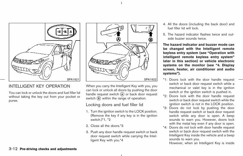
INTELLIGENT KEY OPERATIONYou can lock or unlock the doors and fuel filler lidwithout taking the key out from your pocket orpurse.
When you carry the Intelligent Key with you, youcan lock or unlock all doors by pushing the doorhandle request switch �A or back door requestswitch �B within the range of operation.
Locking doors and fuel filler lid
1. Turn the ignition switch to the LOCK position.(Remove the key if any key is in the ignitionswitch.)*1, *2
2. Close all the doors.*3
3. Push any door handle request switch or backdoor request switch while carrying the Intel-ligent Key with you.*4
4. All the doors (including the back door) andfuel filler lid will lock.
5. The hazard indicator flashes twice and out-side buzzer sounds twice.
The hazard indicator and buzzer mode canbe changed with the Intelligent remotekeyless entry system (see “Operation withintelligent remote keyless entry system”later in this section) or vehicle electronicsystems on the monitor (see “4. Displayscreen, heater, air conditioner and audiosystems”).
*1: Doors lock with the door handle requestswitch or back door request switch while amechanical or valet key is in the ignitionswitch or the ignition switch is pushed in.
*2: Doors lock with the door handle requestswitch or back door request switch while theignition switch is not in the LOCK position.
*3: Doors do not lock by pushing the doorhandle request switch or back door requestswitch while any door is open. A beepsounds to warn you. However, doors lockwith the metal key even if any door is open.
*4: Doors do not lock with door handle requestswitch or back door request switch with theIntelligent Key inside the vehicle and a beepsounds to warn you.However, when an Intelligent Key is inside
SPA1921 SPA1922
3-12 Pre-driving checks and adjustments
� 04.8.3/Z50-D/V5.0 �

the vehicle, doors can be locked with an-other Intelligent Key.
Unlocking doors and fuel filler lid
1. Push the door handle request switch or backdoor request switch once.
Driver’s side:
� The driver door and fuel filler lid unlock.
Front passenger side or back door:
� Only corresponding door unlocks.
2. The hazard indicator flashes once and out-side buzzer sounds once if all doors arecompletely closed with the ignition key in anyposition except the ON position.
3. Push the door handle request switch or backdoor request switch again within 5 seconds.
� All doors and the fuel filler lid unlock.
� The hazard indicator flashes once and out-side buzzer sounds once if all doors arecompletely closed.
All doors will be locked automatically after push-ing the door handle request switch or back doorrequest switch unless one of the following op-erations is performed within 1 minute.
� any door is opened
� the ignition switch is pushed
� the mechanical key or the valet key is insertedinto the ignition switch
Re-lock time can be adjusted or cancelled withthe vehicle electronic systems on the monitor(see “4. Display screen, heater, air conditionerand audio systems”).
The room light will come on for 30 secondswhen the door is unlocked using the requestswitch.
The room light can be turned off without waitingfor 30 seconds by turning the ignition switch tothe ON position or by locking the doors.
OPERATING THE ENGINE
Ignition switch positionsPush in the ignition switch in the range (�A to�B ) when you turn it.
LOCK (Normal parking position) �A :The ignition switch can only be locked in the �Aposition.
The ignition switch will be unlocked when it ispushed in, and turned to the ACC position �Cwhile carrying the Intelligent Key.
SSD0417
Pre-driving checks and adjustments 3-13
� 04.8.3/Z50-D/V5.0 �

ACC (Accessories) �C :This position activates electrical accessoriessuch as the radio, when the engine is notrunning.
ON (Normal operating position) �D :This position turns on the ignition system andelectrical accessories.
START �E :This position starts the engine. As soon as theengine has started, release the switch immedi-ately. It will automatically return to the ON posi-tion.
For important safety information, see “Ignitionswitch” in the “5. Starting and driving” section.
The ignition switch cannot be turned back to theLOCK position unless the shift lever is in Pposition. (It can be turned to only �B .) If theignition switch cannot be turned back to theLOCK position after shifting the shift lever to theP position, turn the ignition switch to the ACCposition once and turn back to the LOCK posi-tion.
CAUTION
Do not leave the vehicle with the igni-tion switch in ACC or ON positions whenthe engine is not running for an ex-tended period. This can discharge thebattery.
Starting the engine
When driving the vehicle, be sure to carry theIntelligent Key with you.
1. Securely depress the brake pedal.
2. Slowly push the ignition switch in.When the Intelligent Key warning light �A inthe instrument panel comes on in green, theignition switch can be turned.
3. Turn the ignition switch to the START posi-tion and the engine will be started.
4. When the engine starts, release the ignitionswitch.
SPA1924
3-14 Pre-driving checks and adjustments
� 04.8.3/Z50-D/V5.0 �

WARNING
Do not start the engine from outside thevehicle through the window. Doing socould lead to an accident and injury. Besure to sit in the driver’s seat to use thekey.
For important safety information, see “Startingthe engine” in the “5. Starting and driving”section.
� When the ignition switch is pushed under thefollowing conditions, the key warning light inthe instrument panel comes on in red. It is notpossible to turn the ignition switch when:
• you do not have the Intelligent Key withyou
• the Intelligent Key battery has run down
• you have a Intelligent Key for anothervehicle with you
� Slowly turn the ignition switch after the keywarning light comes on in green. If it is turnedquickly, it may stick and be difficult to turn.
� The engine may not start if the Intelligent Keyis placed:
• inside the glove box or the door pocket
• on the instrument panel
• in the corner of interior compartment.
� If it is difficult to turn the ignition switch,perform the following:
• Push the ignition switch again and slowlyturn it left and to the right.
• Turn the ignition switch while gently turn-ing the steering wheel to the left or right.
Stopping the engine1. Shift the selector lever to the P position.
2. Turn the ignition switch to the ACC position.
WARNING
When you leave the vehicle, be sure toobserve the following:
� Shift the selector lever to P. (In otherpositions, the ignition switch will notreturn to LOCK.)
� Securely return the ignition switch toLOCK.
� Set the parking brake. Failure to doso could result in unexpected vehiclemovement and could lead to severeinjury.
INTELLIGENT KEY OPERATINGRANGEThe Intelligent Key functions can be used onlywhen you carry the key with you and operate asspecified in the operating range inside or outsidethe vehicle.
When the Intelligent Key battery runs down orwhere there are strong radio waves or noise, theoperating range may be narrower or the key maybe inoperative.
Pre-driving checks and adjustments 3-15
� 04.8.3/Z50-D/V5.0 �

Operating range of the door lock/unlock function
The operating range of the door lock/unlockfunction by pushing the door handle request
switch or the back door request switch is shownin the illustration.
�1 31.5 in (0.8 m) from the door handle requestswitch
�2 31.5 in (0.8 m) from the back door requestswitch
� If you are too close to the door or door glass,the Intelligent Key may not operate.
� If the Intelligent Key is in the operating range,it is possible for anyone who does not carrythe Intelligent Key to lock/unlock the doors bypushing the door handle request switch orthe back door request switch.
Operating range for engine startfunctionThe operating range for starting the engine isinside the vehicle.
� If the Intelligent Key is on the instrumentpanel, inside the glove box or door pocket, orthe corner of interior compartment, it may notbe possible to start the engine.
� If the Intelligent Key is near the door or doorglass outside the vehicle, it may be possibleto start the engine.
SPA1948
SPA1949
3-16 Pre-driving checks and adjustments
� 04.8.3/Z50-D/V5.0 �

WARNING SIGNALSTo help prevent the vehicle from moving unex-pectedly by erroneous operation of the Intelli-gent Key or to help prevent the vehicle frombeing stolen, a chime or buzzer sounds frominside and outside the vehicle and a warninglight comes on in the instrument panel.
When a chime or beep sounds or the warninglight comes on, be sure to check the vehicle andIntelligent Key.
Audible reminder and warning whenlocking the doorsWhen the chime or buzzer sounds from insideand outside the vehicle, check for the following:
� The ignition switch is turned to the LOCKposition.
� The Intelligent Key is not left inside thevehicle.
� Doors are closed securely.
� The selector lever is in the P position.
Audible reminder and warning whenthe engine stops
When the P position selecting warning light �Bin the instrument panel blinks in red:
� Make sure the selector lever is in the Pposition.
When the chime sounds intermittently:
� Make sure the selector lever is in the Pposition and the ignition switch is turned tothe LOCK position.
If the chime sounds continuously when thedriver’s door is opened, check the following:
� The selector lever is in the P position and theignition switch is turned to the LOCK posi-tion.
� The mechanical key or the valet key is notinserted into the ignition switch.
� The warning chime may stop when one of thefollowing is performed.
• Returning the ignition switch to the LOCKposition.
• Removing the mechanical key or the valetkey.
• Closing the doors.
Alarm and warning when the enginestartsWhen the key warning light �A is blinking in redand the outside buzzer sounds, make sure theIntelligent Key is inside the vehicle.
Warning for low battery power� This warning is to let you know that the
battery of the Intelligent Key will run downsoon. Replace it with a new one. Refer to the“8. Maintenance and do-it-yourself” sectionfor battery replacement.
• The green blinking key warning light �Agoes out about 30 seconds after the
SPA1925
Pre-driving checks and adjustments 3-17
� 04.8.3/Z50-D/V5.0 �
ignition switch is turned to ON.
� We recommend replacing the battery at aNISSAN dealer.
Preventing the Intelligent Key frombeing left in the vehicleIf you lock all doors using the power door lockswitch with the Intelligent Key in the vehicle, allof the doors unlock immediately and the buzzerwill warn you when the door is closed.
3-18 Pre-driving checks and adjustments
� 04.8.3/Z50-D/V5.0 �

TROUBLE-SHOOTING GUIDESymptom Possible Cause Remedy
When pushing the doorhandle request switch or theback door request switch
The outside buzzer sounds for approxi-mately 2 seconds. The doors cannot be locked.
Take out the Intelligent Key from the vehicleand push the door handle request switch orthe back door request switch.Turn the ignition switch to the LOCK posi-tion and push the door handle requestswitch or the back door request switchwhile carrying the Intelligent Key with you.Close all the doors securely and push thedoor handle request switch or the back doorrequest switch while carrying the IntelligentKey with you.
When closing the doors
The outside buzzer sounds for approxi-mately 10 seconds.
The ignition switch is not turned to theLOCK position.
Turn the ignition switch to the LOCK posi-tion.
The key warning light in the instrumentpanel blinks in red and the outsidebuzzer sounds 3 times.
The Intelligent Key is not in the vehicle. Be sure to carry the Intelligent Key with you.
The outside buzzer sounds for approxi-mately 3 seconds and all doors unlock.
The Intelligent Key has been left in the ve-hicle.
Take out the Intelligent Key from the vehicleand close the door.
When locking the doors The outside buzzer sounds for approxi-mately 3 seconds and all doors unlock.
The Intelligent Key has been left in the trunkroom.
Take out the Intelligent Key from the vehicleand close the door.
When opening the driver’sdoor A warning chime sounds continuously.
The ignition switch is not in the LOCK posi-tion, or the mechanical key or valet key isinserted into the ignition switch.
Turn the ignition switch to the LOCK posi-tion.Remove the mechanical key or valet keyfrom the ignition switch.
When stopping the engine The P position warning light in the in-strument panel blinks in red. The shift lever is not in the P position. Make sure that the shift lever is in the P po-
sition.When turning the ignitionswitch A warning chime sounds continuously. The ignition switch is not turned to the
LOCK position.Turn the ignition switch to the LOCK posi-tion.
When starting the engine The key warning light in the instrumentpanel blinks in green. The battery charge is low. Replace the battery with a new one. See
“BATTERY REPLACEMENT” on page 8-25.
When pushing the ignitionswitch
The key warning light in the instrumentpanel comes on in red. The Intelligent Key is not in the vehicle.
If the key warning light comes on in redeven while you are carrying the IntelligentKey, the battery is completely discharged.Replace the battery with a new one. See“BATTERY REPLACEMENT” on page 8-25.
Pre-driving checks and adjustments 3-19
� 04.8.4/Z50-D/V5.0 �

Trouble-shooting examples
When it is difficult to turn the ignitionswitch
� Push the ignition switch and turn it to the leftand then to the right.
� While gently turning the steering wheel to theleft or right, turn the ignition switch.
OPERATION WITH INTELLIGENTREMOTE KEYLESS ENTRY SYSTEM
It is possible to lock/unlock all doors, fuel fillerlid, activate the panic alarm and open the win-dows by pushing the buttons on the IntelligentKey from outside the vehicle.
Before locking the doors, make sure thekey is not left in the vehicle.
The LOCK/UNLOCK button on the IntelligentKey can operate at a distance of approximately33 ft (10 m) from the vehicle. (The effectivedistance depends upon the conditions aroundthe vehicle.)As many as 4 Intelligent Key can be used withone vehicle. For information concerning the pur-chase and use of an additional Intelligent Key,contact a NISSAN dealer.
The LOCK and UNLOCK buttons on the Intelli-gent Key will not operate when:
� the Intelligent Key is too far away from thevehicle
� the Intelligent Key battery runs down
After locking with the Intelligent remote keylessentry function, pull the door handle to make surethe doors are securely locked.
The operating range varies depending on theenvironment. To securely operate the LOCK andUNLOCK buttons on the Intelligent Key, ap-proach the vehicle to about 3 ft (1 m) from thedoor.
The panic alarm will not activate when themechanical key or the valet key is in theignition switch.
�A LOCK button�B UNLOCK button�C PANIC alarm
How to use remote keyless entrysystem
Setting hazard indicator and horn(buzzer) mode:
This vehicle is set in hazard indicator and horn(buzzer) mode when you first receive the vehicle.
The hazard indicator and horn (buzzer)mode also can be changed with vehicleelectronic systems on the monitor. See “4.
SPA1926
3-20 Pre-driving checks and adjustments
� 04.8.3/Z50-D/V5.0 �
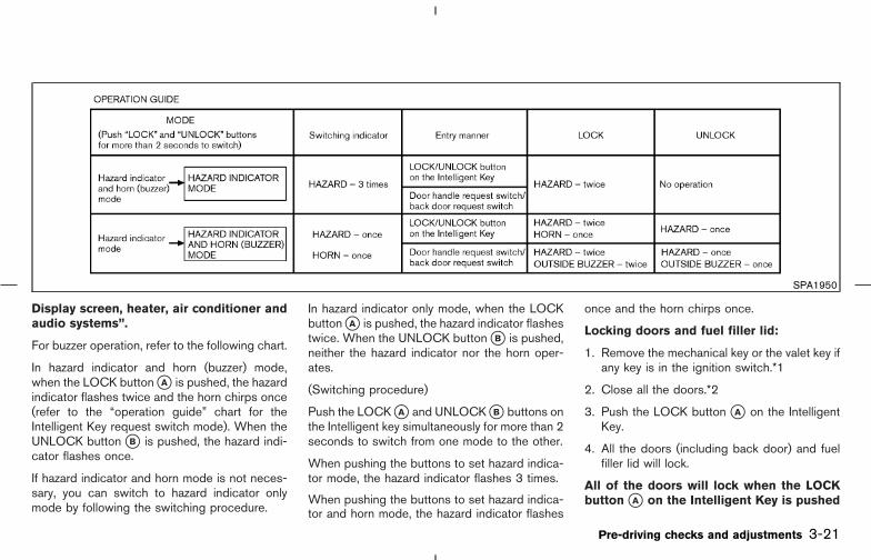
Display screen, heater, air conditioner andaudio systems”.
For buzzer operation, refer to the following chart.
In hazard indicator and horn (buzzer) mode,when the LOCK button �A is pushed, the hazardindicator flashes twice and the horn chirps once(refer to the “operation guide” chart for theIntelligent Key request switch mode). When theUNLOCK button �B is pushed, the hazard indi-cator flashes once.
If hazard indicator and horn mode is not neces-sary, you can switch to hazard indicator onlymode by following the switching procedure.
In hazard indicator only mode, when the LOCKbutton �A is pushed, the hazard indicator flashestwice. When the UNLOCK button �B is pushed,neither the hazard indicator nor the horn oper-ates.
(Switching procedure)
Push the LOCK �A and UNLOCK �B buttons onthe Intelligent key simultaneously for more than 2seconds to switch from one mode to the other.
When pushing the buttons to set hazard indica-tor mode, the hazard indicator flashes 3 times.
When pushing the buttons to set hazard indica-tor and horn mode, the hazard indicator flashes
once and the horn chirps once.
Locking doors and fuel filler lid:
1. Remove the mechanical key or the valet key ifany key is in the ignition switch.*1
2. Close all the doors.*2
3. Push the LOCK button �A on the IntelligentKey.
4. All the doors (including back door) and fuelfiller lid will lock.
All of the doors will lock when the LOCKbutton �A on the Intelligent Key is pushed
SPA1950
Pre-driving checks and adjustments 3-21
� 04.8.3/Z50-D/V5.0 �

even though the ignition switch is in theON position.
5. The hazard indicator flashes twice and thehorn chirps once.
� When the LOCK button �A is pushed with alldoors locked, the hazard indicator flashestwice and the horn chirps once as a reminderthat the doors are already locked.
*1: Doors lock with the Intelligent Key while themechanical key or the valet key is in theignition switch or the ignition switch ispushed in.
*2: Doors do not lock and buzzer sounds whenthe LOCK button is pushed while any dooris open.
Unlocking doors and fuel filler lid:
1. Push the UNLOCK button �B on the Intelli-gent Key once.
� The driver’s door and fuel filler lid unlock
� The hazard indicator flashes once if all doorsare completely closed with the ignition switchin any position except the ON position.
� The interior light turns on and the light timeractivates for 30 seconds when the switch isin the DOOR position with the ignition switchin any position except the ON position.
2. Push the UNLOCK button �B on the Intelli-gent Key again within 5 seconds.
� All doors unlock.
� Back door unlocks.
� The hazard indicator flashes once if all doorsare completely closed.
All doors will be locked automatically unless oneof the following operations is performed within 1minute of pushing the UNLOCK button �B .
� any door is open
� the ignition switch is pushed
� the mechanical key or the valet key is insertedinto the ignition switch
The interior light can be turned off withoutwaiting for 30 seconds by turning the ignitionswitch to the ON position or by locking thedoors with the Intelligent Key.
Opening and closing front windows:
� To open the windows, push the UNLOCKbutton �B for about 3 seconds or turn thedriver’s door key lock with the metal key tothe rear of the vehicle for about 2 secondsafter the door is unlocked.
To stop opening, release the UNLOCK but-ton �B or turn the key to the neutral position.
� To close the front windows, turn the driver’sdoor key lock to the front of the vehicle forabout 2 seconds after the door is locked.
To stop closing, turn the key to the neutralposition.
The door windows will open or close whileturning the metal key. See “Doors” earlier in thissection.
Using the panic alarm:
If you are near your vehicle and feel threatened,you may activate the alarm to call attention asfollows:
1. Push the PANIC button �C on the IntelligentKey for longer than 0.5 seconds with themetal key removed from the ignition switch orthe ignition switch not pushed in.
2. The theft warning alarm and headlights willstay on for 25 seconds.
3. The panic alarm stops when:
� It has run for 25 seconds, or
� Any of the buttons on the Intelligent Key arepushed.
3-22 Pre-driving checks and adjustments
� 04.8.3/Z50-D/V5.0 �
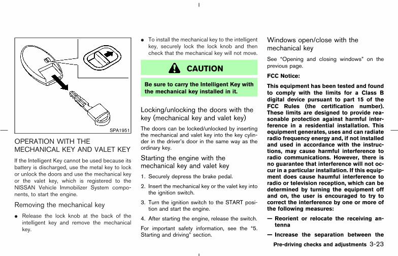
OPERATION WITH THEMECHANICAL KEY AND VALET KEY
If the Intelligent Key cannot be used because itsbattery is discharged, use the metal key to lockor unlock the doors and use the mechanical keyor the valet key, which is registered to theNISSAN Vehicle Immobilizer System compo-nents, to start the engine.
Removing the mechanical key
� Release the lock knob at the back of theintelligent key and remove the mechanicalkey.
� To install the mechanical key to the intelligentkey, securely lock the lock knob and thencheck that the mechanical key will not move.
CAUTION
Be sure to carry the Intelligent Key withthe mechanical key installed in it.
Locking/unlocking the doors with thekey (mechanical key and valet key)The doors can be locked/unlocked by insertingthe mechanical and valet key into the key cylin-der in the driver’s door in the same way as theordinary key.
Starting the engine with themechanical key and valet key1. Securely depress the brake pedal.
2. Insert the mechanical key or the valet key intothe ignition switch.
3. Turn the ignition switch to the START posi-tion and start the engine.
4. After starting the engine, release the switch.
For important safety information, see the “5.Starting and driving” section.
Windows open/close with themechanical key
See “Opening and closing windows” on theprevious page.
FCC Notice:
This equipment has been tested and foundto comply with the limits for a Class Bdigital device pursuant to part 15 of theFCC Rules (the certification number).These limits are designed to provide rea-sonable protection against harmful inter-ference in a residential installation. Thisequipment generates, uses and can radiateradio frequency energy and, if not installedand used in accordance with the instruc-tions, may cause harmful interference toradio communications. However, there isno guarantee that interference will not oc-cur in a particular installation. If this equip-ment does cause haumful interference toradio or television reception, which can bedetermined by turning the equipment offand on, the user is encouraged to try tocorrect the interference by one or more ofthe following measures:
— Reorient or relocate the receiving an-tenna
— Increase the separation between the
SPA1951
Pre-driving checks and adjustments 3-23
� 04.8.3/Z50-D/V5.0 �

equipment and the receiver
— Connect the equipment into an outlet ona circuit different from that to which thereceiver is connected.
— Consult the dealer or an experiencedradio/TV technician for help.
1. Pull the hood lock release handle �1 locatedbelow the instrument panel; the hood willthen spring up slightly.
2. Move the lever �2 at the front of the hoodwith your fingertips and raise the hood.
3. When closing the hood, slowly close thehood and make sure it locks into place.
WARNING
� Make sure the hood is completelyclosed and latched before driving.Failure to do so could cause the hoodto fly open and result in an accident.
� If you see steam or smoke comingfrom the engine compartment, toavoid injury do not open the hood.
SPA1578
HOOD
3-24 Pre-driving checks and adjustments
� 04.8.3/Z50-D/V5.0 �
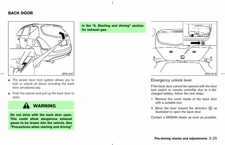
� The power door lock system allows you tolock or unlock all doors including the backdoor simultaneously.
� Push the opener and pull up the back door toopen.
WARNING
Do not drive with the back door open.This could allow dangerous exhaustgases to be drawn into the vehicle. See“Precautions when starting and driving”
in the “5. Starting and driving” sectionfor exhaust gas.
Emergency unlock leverIf the back door cannot be opened with the doorlock switch or remote controller due to a dis-charged battery, follow the next steps.
1. Remove the cover inside of the back doorwith a suitable tool.
2. Move the lever toward the direction �A asillustrated to open the back door.
Contact a NISSAN dealer as soon as possible.
SPA1947 SPA1915
BACK DOOR
Pre-driving checks and adjustments 3-25
� 04.8.3/Z50-D/V5.0 �

WARNING
� Always be sure the back door hasbeen closed securely to prevent itfrom opening while driving.
� Do not drive with the back door open.This could allow dangerous exhaustgases to be drawn into the vehicle.
OPEN THE FILLER LID
To open the fuel filler lid, unlock it using one ofthe following operations, then push the right-hand side of the lid �A .
� Push the unlock button on the remote keylessentry once.
� Insert the key into the door lock cylinder andturn the door key clockwise twice.
� Push the power door lock switch to theunlock side.
� Push the driver’s side door handle request
switch once (Intelligent Key equippedmodel).
� Push the passenger side door handle requestswitch or back door request switch twice(Intelligent Key equipped model).
To lock, close the fuel filler lid and lock the doors.
SPA1580
FUEL FILLER LID
3-26 Pre-driving checks and adjustments
� 04.8.3/Z50-D/V5.0 �

FUEL FILLER CAP
The fuel filler cap is a ratcheting type. Turn thecap counterclockwise �A to remove.
To tighten, turn the cap clockwise until ratchet-ing clicks are heard.
Put the fuel filler cap on the cap holder �B whilerefueling.
WARNING
� Gasoline is extremely flammable and
highly explosive under certain condi-tions. You could be burned or seri-ously injured if it is misused or mis-handled. Always stop the engine anddo not smoke or allow open flamesor sparks near the vehicle when refu-eling.
� Fuel may be under pressure. Turn thecap a third of a turn, and wait for any“hissing sound” to stop to preventfuel from spraying out and possiblycausing personal injury. Then removethe cap.
� Do not attempt to top off the fueltank after the fuel pump nozzle shutsoff automatically.Continued refueling may cause fueloverflow, resulting in fuel spray andpossibly a fire.
� Use only an original equipment typefuel filler cap as a replacement. It hasa built-in safety valve needed forproper operation of the fuel systemand emission control system. An in-correct cap can result in a seriousmalfunction and possible injury. Itcould also cause the malfunc-tion indicator lamp to come on.
� Do not fill a portable fuel container inthe vehicle or trailer. Static electricitycan cause an explosion of flammableliquid, vapor or gas in any vehicle ortrailer. To reduce the risk of seriousinjury or death when filling portablefuel containers:
— Always place the container on theground when filling.
— Do not use electronic devices
SPA1581A
Pre-driving checks and adjustments 3-27
� 04.8.3/Z50-D/V5.0 �

when filling.
— Keep the pump nozzle in contactwith the container while you arefilling it.
— Use only approved portable fuelcontainers for flammable liquid.
� Never pour fuel into the throttle bodyto attempt to start your vehicle.
CAUTION
� If fuel is spilled on the vehicle body,flush it away with water to avoidpaint damage.
� Tighten until the fuel filler cap clicks.Failure to tighten the fuel filler capproperly may cause the mal-function indicator lamp (MIL) to illu-minate. If the lamp illuminatesbecause the fuel filler cap is loose ormissing, tighten or install the cap andcontinue to drive the vehicle. The
lamp should turn off after a fewdriving trips. If the lamp does
not turn off after a few driving trips,have the vehicle inspected by aNISSAN dealer.
� For additional information, see the“Malfunction indicator lamp (MIL)” inthe “Instruments and controls” sec-tion.
TILT OPERATION
The steering wheel will pop up when the locklever is pulled as illustrated �1 .
Keep holding the lock lever and adjust thesteering wheel to the desired position �2 .
Release the lock lever to lock the steering wheel.
WARNING
� Do not adjust the steering wheelwhile driving. You could lose control
SPA1582
STEERING WHEEL
3-28 Pre-driving checks and adjustments
� 04.8.3/Z50-D/V5.0 �
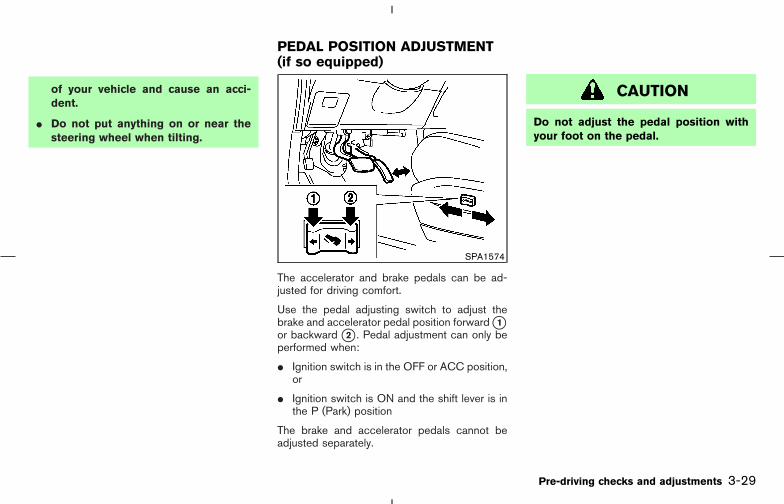
of your vehicle and cause an acci-dent.
� Do not put anything on or near thesteering wheel when tilting.
The accelerator and brake pedals can be ad-justed for driving comfort.
Use the pedal adjusting switch to adjust thebrake and accelerator pedal position forward �1or backward �2 . Pedal adjustment can only beperformed when:
� Ignition switch is in the OFF or ACC position,or
� Ignition switch is ON and the shift lever is inthe P (Park) position
The brake and accelerator pedals cannot beadjusted separately.
CAUTION
Do not adjust the pedal position withyour foot on the pedal.
SPA1574
PEDAL POSITION ADJUSTMENT(if so equipped)
Pre-driving checks and adjustments 3-29
� 04.8.3/Z50-D/V5.0 �

CAUTION
� Do not store the main sun visor be-fore storing the extension sun visor.
� Do not pull the extension sun visorforcedly downward.
1. To block out glare from the front, swing downthe main sun visor �1 .
2. To block glare from the side, remove the mainsun visor from the center mount and swing itto the side �2 .
3. Draw out the extension sun visor �3 from themain sun visor �4 to block further glare.
INSIDE MIRROR
While holding the inside rearview mirror, adjustthe mirror angles until the desired position isachieved.
The adjusting lever �1 can be operated whenthe glare from the headlights of the vehiclebehind you obstructs your vision at night.
WARNING
Use the night position only when neces-sary, because it reduces rear view clar-
SPA1592B
SPA1756
SUN VISORS MIRRORS
3-30 Pre-driving checks and adjustments
� 04.8.3/Z50-D/V5.0 �

ity.
AUTOMATIC ANTI-GLARE INSIDEMIRROR (if so equipped)
The inside mirror is designed so that it automati-cally changes reflection according to the inten-sity of the headlights of the vehicle following you.
The anti-glare system will be automaticallyturned on when you turn the ignition switch tothe ON position.
When the inside MIRROR switch �A is turnedon (The indicator light �B will illuminate), exces-sive glare from the headlights of the vehiclebehind you will be reduced. Push the MIRRORswitch �A to turn the system off (the indicator
light goes off), and the inside mirror will operatenormally.
To turn on the system again, push the MIRRORswitch once again.
For the HomeLink Universal Transceiver andthe compass display, see the description in the“2. Instruments and controls” section.
Do not hang any object on the mirror orapply glass cleaner. Doing so will reducethe sensitivity of the sensor, resulting inimproper operation.
SPA1448B
Pre-driving checks and adjustments 3-31
� 04.8.3/Z50-D/V5.0 �

OUTSIDE MIRRORS
WARNING
Objects viewed in the outside mirror onthe passenger side are closer than theyappear. Be careful when moving to theright. Using only this mirror could causean accident. Use the inside mirror orglance over your shoulder to properlyjudge distances to other objects.
The outside mirror switch, located in front of the
shift lever, will operate only when the ignitionswitch is in the ACC or ON position.
Move the switch to right �A or left �B to selectthe right or left outside mirror, then adjust themirror to the desired position by pushing thebutton �C .
Foldable outside mirrorsFold the outside mirror by pushing it toward therear of the vehicle.
SPA1449A SPA1829
3-32 Pre-driving checks and adjustments
� 04.8.3/Z50-D/V5.0 �
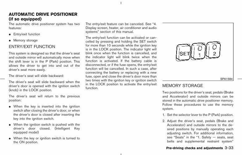
The automatic drive positioner system has twofeatures:
� Entry/exit function
� Memory storage
ENTRY/EXIT FUNCTION
This system is designed so that the driver’s seatand outside mirror will automatically move whenthe shift lever is in the P (Park) position. Thisallows the driver to get into and out of thedriver’s seat more easily.
The driver’s seat will slide backward:
The driver’s seat will slide backward when thedriver’s door is opened with the ignition switch(knob) in the LOCK position.
The driver’s seat will return to the previousposition:
� When the key is inserted into the ignitionswitch after closing the driver’s door, or whenthe driver’s door is closed after inserting thekey into the ignition switch.
� When the ignition switch is pushed with thedriver’s door closed. (Intelligent Keyequipped model)
� When the key or ignition switch is turned tothe ON position.
The entry/exit feature can be canceled. See “4.Display screen, heater, air conditioner and audiosystems” section of this manual.
The entry/exit function can be activated or can-celled by pressing and holding the SET switchfor more than 10 seconds while the ignition keyis in the LOCK position. The indicator light willblink once when the function is cancelled, andthe indicator light will blink twice when thefunction is activated. If the battery cable isdisconnected, or if the fuse opens, the entry/exitfunction will be cancelled. In such a case, afterconnecting the battery or replacing with a newfuse, open and close the driver’s door more thantwo times with the ignition key or ignition switchin the LOCK position to activate the entry/exitfunction.
MEMORY STORAGE
Two positions for the driver’s seat, pedals (Brakeand Accelerator) and outside mirrors can bestored in the automatic drive positioner memory.Follow these procedures to use the memorysystem.
1. Set the selector lever to the P (Park) position.
2. Adjust the driver’s seat, pedals (Brake andAccelerator) and outside mirrors to the de-sired positions by manually operating eachadjusting switch. For additional information,see “Seats” in the “1. Safety — seats, seatbelts and supplemental restraint system”
SPA1584
AUTOMATIC DRIVE POSITIONER(if so equipped)
Pre-driving checks and adjustments 3-33
� 04.8.3/Z50-D/V5.0 �

section and “Pedal position adjustment” and“Outside mirrors” earlier in this section.
3. Turn the ignition ON.
4. Push the SET switch and, within 5 seconds,push the memory switch (1 or 2) fully for atleast 1 second.
The indicator light for the pushed memoryswitch will come on and stay on for approxi-mately 5 seconds after pushing the switch.After the indicator light goes off, the selectedpositions are stored in the selected memory(1 or 2).
If memory is stored in the same memory switch,the previous memory will be deleted.
Linking a remote keyless entry to astored memory position
A remote keyless entry can be linked to a storedmemory position with the following procedure.
1. Follow the steps for storing a memory posi-tion.
2. While the indicator light for the memoryswitch being set is illuminated for 5 seconds,push the unlock button on the remote keylessentry. The indicator light will blink. After theindicator light goes off, the remote keylessentry is linked to that memory setting.
With the key removed from the ignition switch,push the unlock button on the keyfob. Thedriver’s seat, pedals (Brake and Accelerator)and outside mirrors will move to the memorizedposition.
Confirming memory storage� Turn the ignition switch to the ON position
and push the SET switch. If the main memoryhas not been stored, the indicator light willcome on for approximately 0.5 seconds.When the memory has stored the position,the indicator light will stay on for approxi-mately 5 seconds.
Selecting the memorized position1. Set the sift selector lever to the P (Park)
position.
2. Turn the ignition ON.
3. Push the memory switch (1 or 2) fully for atleast 1 second.
The driver’s seat, pedals (Brake and Accel-erator) and outside mirrors will move to thememorized position with the indicator lightflashing, and then the light will stay on forapproximately 5 seconds.
SYSTEM OPERATIONThe automatic drive positioner system will not
work or will stop operating under the followingconditions:
� when the vehicle speed is above 4 MPH (7km/h).
� when any two or more of the memoryswitches and the SET switch is simulta-neously pushed while the automatic drivepositioner is operating.
� when the adjusting switch for the driver’sseat, pedals and outside mirror are operatedwhile the automatic drive positioner is oper-ating.
� when the memory switch (1 or 2) and theSET switch is not pushed for at least 1second.
� when the seat has been already moved to thememorized position.
� when no seat position is stored in thememory switch.
� when the engine is started while moving theautomatic drive positioner.
� when the shift selector lever is moved fromthe P position to any other position (However,it will not be cancelled if the switch is pushedwhile the seat is returning to the previouspositions (entry/exit function).).
3-34 Pre-driving checks and adjustments
� 04.8.3/Z50-D/V5.0 �

MEMO
Pre-driving checks and adjustments 3-35
� 04.8.3/Z50-D/V5.0 �

MEMO
3-36 Pre-driving checks and adjustments
� 04.8.3/Z50-D/V5.0 �

4 Display screen, heater, air conditioner andaudio systems
Safety note .............................................................................. 4-2Control panel buttons — without navigation system.... 4-2
How to use joystick and “ENTER” button................. 4-3How to use “PREV” button ........................................... 4-3How to use the “TRIP” button...................................... 4-3How to use “FUEL ECON” BUTTON ........................ 4-4Clock ................................................................................... 4-4How to use “E/M” button .............................................. 4-4How to use “MAINT” (Maintenance) button ............. 4-5How to use “SETTING” button .................................... 4-6“DAY/NIGHT” utton......................................................... 4-7
Control panel buttons — with navigation system.......... 4-8How to use joystick and “ENTER” button................. 4-8How to use “PREV” button ........................................... 4-8Setting up the start-up screen ..................................... 4-9How to use the “TRIP” button...................................... 4-9Maintenance notice....................................................... 4-11How to use the “SETTING” button .......................... 4-12“DAY/NIGHT” button.................................................... 4-17
Rear view monitor (if so equipped) ................................ 4-17How to read the displayed lines................................ 4-18Rear view monitor setting............................................ 4-18
Operating tips................................................................. 4-18Ventilators.............................................................................. 4-19Heater and air conditioner (Automatic) ......................... 4-20
Automatic operation...................................................... 4-21Manual operation ........................................................... 4-22Operating tips................................................................. 4-22In-cabin microfilter......................................................... 4-23
Servicing air conditioner .................................................... 4-23Audio system........................................................................ 4-24
FM radio reception........................................................ 4-24AM radio reception ....................................................... 4-25Satellite radio reception............................................... 4-25Audio operation precautions....................................... 4-25FM-AM-SAT radio with cassette player andcompact disc (CD) player (TYPE A)/CD changer(TYPE B).......................................................................... 4-28CD care and cleaning .................................................. 4-34Steering switch for audio control(if so equipped).............................................................. 4-35Antenna ............................................................................ 4-36
Car phone or CB radio .................................................... 4-36
� 04.8.3/Z50-D/V5.0 �

WARNING
� Positioning of the heating or air con-ditioning controls and display con-trols should not be done while driv-ing, in order that full attention maybe given to the driving operation.
� Do not disassemble or modify thissystem. If you do, it may result inaccidents, fire, or electrical shock.
� Do not use this system if you noticeany abnormality, such as a frozenscreen or lack of sound. Continueduse of the system may result in acci-dent, fire or electric shock.
� In case you notice any foreign objectin the system hardware, spill liquidon it, or notice smoke or smell com-ing from it, stop using the systemimmediately and contact a NISSANdealer. Ignoring such conditions maylead to accidents, fire, or electricalshock.
SAA0795A
SAFETY NOTE CONTROL PANEL BUTTONS —WITHOUT NAVIGATION SYSTEM
4-2 Display screen, heater, air conditioner and audio systems
� 04.8.3/Z50-D/V5.0 �

1. “TRIP” drive computer button; refer to page4-3.
2. “FUEL ECON” button; refer to page 4-4.
3. Clock adjust button; refer to page 4-4.
4. “TRIP RESET” button; refer to page 4-3.
5. “E/M” button; refer to page 4-4.
6. “MAINT” maintenance button; refer to page4-5.
7. “SETTING” button; refer to page 4-6.
8. JOYSTICK and “ENTER” button; refer topage 4-3.
9. “PREV” previous button; refer to page 4-3.
10. “DAY/NIGHT” brightness control button;refer to page 4-7.
Make sure the engine is running before usingthis system.
Using the system with the engine off (igni-tion ON or ACC) for extended periods willdrain the battery power, and the enginemay not start.
HOW TO USE JOYSTICK AND“ENTER” BUTTONChoose an item on the display using the joystick.Push the “ENTER” button only when the use of
it is instructed on the display.
HOW TO USE “PREV” BUTTONFinish setup:
If you push the “PREV” button after the setup iscompleted, the display will return to the previousscreen.
HOW TO USE THE “TRIP” BUTTON
When the “TRIP” button is pushed, the followingmodes will display on the screen.
TRIP 1 (TIME, DIST, AVG) → TRIP 2 (TIME,DIST, AVG) → OFF
You can set the two kinds of journey time (TIME— max 99 hours 59 minutes), trip odometer(DIST — mile or km) and average speed (AVG—MPH or km/h).
To reset the TRIP 1 or TRIP 2, push the “TRIP”button or the “TRIP RESET” button for morethan approximately 1.5 seconds.
SAA0796
Display screen, heater, air conditioner and audio systems 4-3
� 04.8.3/Z50-D/V5.0 �

HOW TO USE “FUEL ECON”BUTTON
The average fuel consumption (MPG or L/100km) and the distance to empty (DTE — MI or km)will appear on the screen when the “FUELECON” button is pushed.
Average fuel consumption(Mpg or L/100 km)The average fuel consumption mode shows theaverage fuel consumption since the last reset.Resetting is done by pushing the “TRIP RESET”or “FUEL ECON” button for more than approxi-mately 1.5 seconds.
The display is updated every 30 seconds. Atabout the first 30 seconds and 1/3 miles (500m) after a reset or connecting battery cable, thedisplay will show (----).
Distance to empty (DTE — mile orkm)
The distance to empty (DTE) mode provides youwith an estimation of the distance that can bedriven before refueling. The DTE is constantlybeing calculated, based on the amount of fuel inthe fuel tank and the actual fuel consumption.
The display is updated every 30 seconds.
When the fuel level is low, the DTE display willchange to (*).
NOTE:
� The DTE reading may not change fromthe previous reading if the amount offuel added is small.
� Fuel moving in the tank while drivingmay cause the reading to momentarilychange.
CLOCKThe digital clock displays time when the ignitionswitch is in ACC or ON.
If the battery cable is disconnected, the
clock will not indicate the correct time.Readjust the time.
Adjusting the timeTo adjust the time, push the “H” or “M” button formore than approximately 1.5 seconds. The timeindicator will flash.
Push the H button to adjust the hour.
Push the M button to adjust the minute.
To finish the adjusting, push the “PREV” buttonor the screen will return to normal after 10seconds.
HOW TO USE “E/M” BUTTONYou can change the unit as follows using the“E/M” (English/Metric) button.
Unit: US — Mile, °F, MPGMetric — km, °C, L/100 km
SAA0797
4-4 Display screen, heater, air conditioner and audio systems
� 04.8.3/Z50-D/V5.0 �
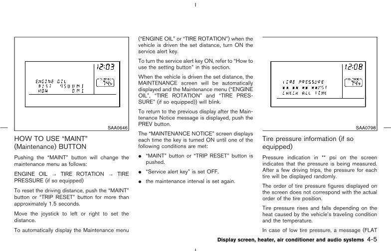
HOW TO USE “MAINT”(Maintenance) BUTTON
Pushing the “MAINT” button will change themaintenance menu as follows:
ENGINE OIL → TIRE ROTATION → TIREPRESSURE (if so equipped)
To reset the driving distance, push the “MAINT”button or “TRIP RESET” button for more thanapproximately 1.5 seconds.
Move the joystick to left or right to set thedistance.
To automatically display the Maintenance menu
(“ENGINE OIL” or “TIRE ROTATION”) when thevehicle is driven the set distance, turn ON theservice alert key.
To turn the service alert key ON, refer to “How touse the setting button” in this section.
When the vehicle is driven the set distance, theMAINTENANCE screen will be automaticallydisplayed and the Maintenance menu (“ENGINEOIL”, “TIRE ROTATION” and “TIRE PRES-SURE” (if so equipped)) will blink.
To return to the previous display after the Main-tenance Notice message is displayed, push thePREV button.
The “MAINTENANCE NOTICE” screen displayseach time the key is turned ON until one of thefollowing conditions are met:
� “MAINT” button or “TRIP RESET” button ispushed.
� “Service alert key” is set OFF.
� the maintenance interval is set again.
Tire pressure information (if soequipped)
Pressure indication in ** psi on the screenindicates that the pressure is being measured.After a few driving trips, the pressure for eachtire will be displayed randomly.
The order of tire pressure figures displayed onthe screen does not correspond with the actualorder of the tire position.
Tire pressure rises and falls depending on theheat caused by the vehicle’s traveling conditionand the temperature.
In case of low tire pressure, a message (FLAT
SAA0646 SAA0798
Display screen, heater, air conditioner and audio systems 4-5
� 04.8.3/Z50-D/V5.0 �

TIRE or CHECK ALL TIRE) is displayed on thescreen:
FLAT TIRE — low tire pressure.
WARNING
When a spare tire is mounted or a wheelis replaced, the pressure of that tire willnot be indicated and not be monitoredby the low tire pressure warning system.Contact a NISSAN dealer as soon aspossible for tire replacement and/orsystem resetting.
HOW TO USE “SETTING” BUTTONPushing the “SETTING” button will change thesettings menu as follows:
�1 DISPLAY ON/OFF
�2 LANGUAGE
�3 BEEP SET
�4 SERVICE ALERT
�5 PERSONALIZED SETTINGS MENU
Display ON/OFFTo turn off the screen, select the “OFF” key ofthe “Display ON/OFF” using the joystick.
The screen will change to “CONFIRM DISPLAYOFF YES or NO”.
If “YES” key is selected using the joystick, thescreen will turn off after 2 beep sound andapproximately 1 second.
To turn on the screen, push the “SETTING”, tripcontrol, air conditioner (except rear window de-froster button) or audio button.
LanguageThe language can be changed to “English” or“Francais” using the joystick.
Beep setIf the beep set “OFF” key is selected using thejoystick, the beep sound will not operate. (exceptsome caution beep sounds)
Service alertIf the service alert “ON” key is selected, theinformation will be displayed when the engine oiland the tire rotation reaches the preset drivingdistance.
Personalized setting menuYou can set the electronic systems as followsusing the joystick.
Slide back DR seat on exit:
The driver’s seat automatically moves back andreturns to the original position for ease of exitand entry.
Remote unlock door logic:
This key can switch the unlock doors of the 1stunlocking operation as follows:
Only the driver side door ←→ All the doors
Horn chirp with remote*:
This key changes the horn chirp mode thatoccurs when pushing the LOCK button on thekeyfob.
Lights flash with remote*:
This key changes the hazard indicator flashmode that occurs when pushing the LOCK orUNLOCK button on the keyfob.
* Even if you change the horn chirp or thehazard flash with the keyfob, the changemay not be reflected in the display. Usethe keyfob to return to the previousmode.
4-6 Display screen, heater, air conditioner and audio systems
� 04.8.3/Z50-D/V5.0 �

Auto re-lock time:
The length of the auto door re-lock time can beset. Select the “Auto Re-Lock time” key, thenmove the joystick to adjust the time.
Auto headlights sensitivity:
Automatic light illumination can be set as de-sired.
Select the “Sensitivity of Automatic Headlights”key, then move the joystick to the left (lower) orright (higher).
Auto headlights off delay:
You can control how long it takes the automaticturn off timer to extinguish the headlights in theAUTO position.
Select the “Automatic Headlights Off Delay” key,then move the joystick to the left or right toadjust the timer.
Speed sensing wiper interval:
This key turns on and off the driving speeddependent intermittent wiper function.
Confirm reset settings:
To display the “Confirm Reset Settings”, select“YES”.When this key is selected and turned on usingthe “ENTER” button, all settings made by PER-
SONALIZED SETTINGS will return to the initialconditions.
Return all settings to default:
When this key is selected and turned on usingthe joystick, all settings made by personalizedsetting menu will return to the initial conditions.
“DAY/NIGHT” BUTTONTo change the display brightness, push the“DAY/NIGHT” button. Pushing the button againwill change the display to DAY or NIGHT dis-play. Then, adjust the brightness moving thejoystick right or left.
If no operation is done within 10 seconds, or ifthe “PREV” button is pushed, the display willreturn to the previous display.
Pushing the “DAY/NIGHT” button for more thanapproximately 1.5 seconds will turn the displayoff. The screen will change to “CONFIRM DIS-PLAY OFF YES or NO”.
Display screen, heater, air conditioner and audio systems 4-7
� 04.8.3/Z50-D/V5.0 �

1. “TRIP” drive computer button; refer to page4-9.
2. “SETTING” button; refer to page 4-12.
3. Joystick and “ENTER” push button; refer topage 4-8.
4. “PREV” previous button; refer to page 4-8.
5. “DAY/NIGHT” brightness control button; re-fer to page 4-17.
6 - 10. For Navigation system control buttons�A ; refer to the separate NavigationOwner’s Manual.
When you use this system, make sure the engineis running.
If you use the system with the engine notrunning (ignition ON or ACC) for a longtime, it will use up all the battery power,and the engine will not start.
HOW TO USE JOYSTICK AND“ENTER” BUTTONChoose an item on the display using the joystickand push the “ENTER” button for operation.
HOW TO USE “PREV” BUTTONThis has two functions.
� Go back to the previous display (cancel).SAA0648A
CONTROL PANEL BUTTONS —WITH NAVIGATION SYSTEM
4-8 Display screen, heater, air conditioner and audio systems
� 04.8.3/Z50-D/V5.0 �

If you touch “PREV” button during setup, thesetup will be canceled and/or the display willreturn to the previous screen.
� Finish setup.
If you touch this button after the setup is com-pleted, the setup will start over, and the displaywill return to the climate control or Audio mode,and Navigation screen.
SETTING UP THE START-UPSCREENWhen you turn the ignition switch to ACC, theSYSTEM START-UP warning is displayed onthe screen. Read the warning and select the“I AGREE” (English) or “ENTER” (Francais) keythen push the “ENTER” button.
If you do not push the “ENTER” button, thissystem will not proceed to the next step display.
If you do not touch the button or screen key formore than 1 minute on the TRIP, SETTING orSTART-UP screen, the screen will change toTRIP screen automatically.
To proceed to the next step, refer to the separateNavigation system Owner’s Manual.
HOW TO USE THE “TRIP” BUTTONWhen the “TRIP” button is pushed, the followingmodels will display on the screen.
Warning message (if there are any) → TRIP 1(Elapsed Time, Driving Distance, AverageSpeed) → TRIP 2 → FUEL ECONOMY (Aver-age Fuel Economy, Distance to Empty) →MAINTENANCE (Engine Oil, Tire Rotation andTire Pressure — if so equipped).
Trip 1, trip 2 and fuel economy itemsTo reset the TRIP 1, TRIP 2 and FUELECONOMY, select the “RESET” key using thejoystick and push the “ENTER” button or pushthe “TRIP” button for more than approximately1.5 seconds.
SAA0654
Display screen, heater, air conditioner and audio systems 4-9
� 04.8.3/Z50-D/V5.0 �

Maintenance itemsYou can set the engine oil and the tire rotationinterval.
And the tire pressure will appear on the screen(if the tire pressure system is equipped).
To display the setting of the maintenance inter-val, select the “Engine Oil” or “Tire Rotation” keyusing the joystick and push the “ENTER” button.
To set the maintenance interval, select the“Maintenance Schedule” key by using the joy-stick and push the joystick to right or left.
To reset the maintenance interval, select the“RESET” key using the joystick and push the“ENTER” button.
To display the MAINTENANCE NOTICE, auto-matically when setting trip distance is reached,select the “Display Maintenance Notification”key and push the “ENTER” button.
SAA0695 SAA0655 SAA0656
4-10 Display screen, heater, air conditioner and audio systems
� 04.8.3/Z50-D/V5.0 �
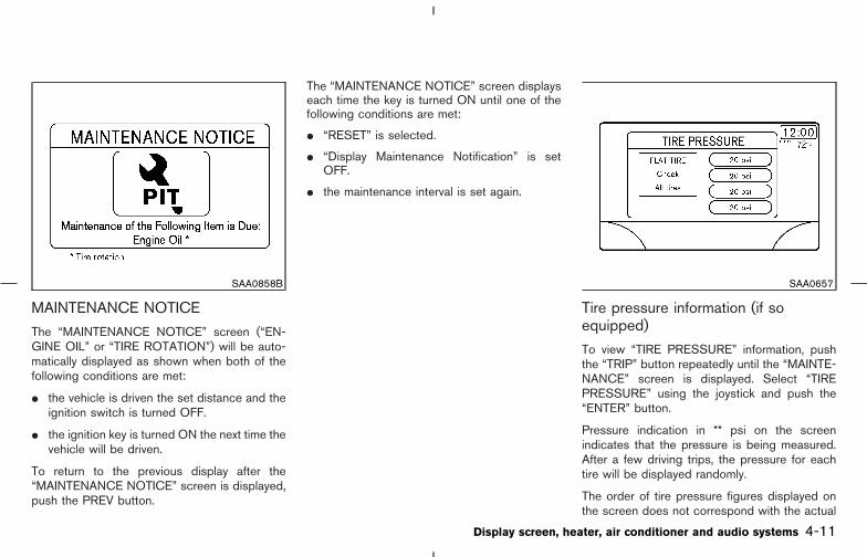
MAINTENANCE NOTICE
The “MAINTENANCE NOTICE” screen (“EN-GINE OIL” or “TIRE ROTATION”) will be auto-matically displayed as shown when both of thefollowing conditions are met:
� the vehicle is driven the set distance and theignition switch is turned OFF.
� the ignition key is turned ON the next time thevehicle will be driven.
To return to the previous display after the“MAINTENANCE NOTICE” screen is displayed,push the PREV button.
The “MAINTENANCE NOTICE” screen displayseach time the key is turned ON until one of thefollowing conditions are met:
� “RESET” is selected.
� “Display Maintenance Notification” is setOFF.
� the maintenance interval is set again.
Tire pressure information (if soequipped)
To view “TIRE PRESSURE” information, pushthe “TRIP” button repeatedly until the “MAINTE-NANCE” screen is displayed. Select “TIREPRESSURE” using the joystick and push the“ENTER” button.
Pressure indication in ** psi on the screenindicates that the pressure is being measured.After a few driving trips, the pressure for eachtire will be displayed randomly.
The order of tire pressure figures displayed onthe screen does not correspond with the actual
SAA0858B SAA0657
Display screen, heater, air conditioner and audio systems 4-11
� 04.8.3/Z50-D/V5.0 �

order of the tire position.
Tire pressure rises and falls depending on theheat caused by the vehicle’s traveling conditionand the temperature.
In case of low tire pressure, a message isdisplayed on the screen:
FLAT TIRE — low tire air pressure.
WARNING
When a spare tire is mounted or a wheelis replaced, the pressure of that tire willnot be indicated and not be monitoredby the low tire pressure warning system.Contact a NISSAN dealer as soon aspossible for tire replacement and/orsystem resetting.
* — Refer to the separate Navigation systemOwner’s Manual.
HOW TO USE THE “SETTING”BUTTONThe SETTINGS screen will appear when the“SETTING” button is pushed.
“Display” settings
The DISPLAY SETTINGS screen will appearwhen selecting the “Display” key and pushingthe “ENTER” button.
Brightness/Contrast/Map Background:
To adjust the brightness and contrast of thescreen, select the “Brightness/Contrast/MapBackground” key and push the “ENTER” button.Then you can adjust the brightness to Darker orBrighter, the contrast to Lower or Higher usingthe joystick.
The Map Background is related to the navigation
SAA0649A SAA0652
4-12 Display screen, heater, air conditioner and audio systems
� 04.8.3/Z50-D/V5.0 �
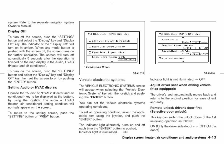
system. Refer to the separate navigation systemOwner’s Manual.
Display Off:
To turn off the screen, push the “SETTING”button and select the “Display” key and “DisplayOff” key. The indicator of the “Display Off” willturn on in amber. When any mode button ispushed with the screen off, the screen turns onfor further operation. The screen will turn offautomatically 5 seconds after the operation isfinished on the map display in the Audio, HVAC(Heater and air conditioner).
To turn on the screen, push the “SETTING”button and select the “Display” key and “DisplayOff” key, then set the screen to on by pushingthe “ENTER” button.
Setting Audio or HVAC display:
Choose the “Audio” or “HVAC” (Heater and airconditioner) key to be displayed at the bottom,by using the joystick. The audio or HVAC(heater, air conditioner) setting condition willnormally appear on the screen.
To return to the setting screen, push the“SETTING” button or “PREV” button.
Vehicle electronic systems
The VEHICLE ELECTRONIC SYSTEMS screenwill appear when selecting the “Vehicle Elec-tronic Systems” key with the joystick and push-ing the “ENTER” button.
You can set the various electronic systemsoperating conditions.
To set an operating condition, select the appli-cable item using the joystick, and push the“ENTER” button.
The indicator light alternately turns on and offeach time the “ENTER” button is pushed.Indicator light is illuminated. — ON
Indicator light is not illuminated. — OFF
Adjust driver seat when exiting vehicle(if so equipped):
The driver’s seat automatically moves back andreturns to the original position for ease of exitand entry.
Remote unlock driver’s door first(Selective door unlock):
This key can switch the unlock doors of the 1stunlocking operation as follows:
ON (Only the driver side door) ←→ OFF (All thedoors)
SAA1029 SAA0794
Display screen, heater, air conditioner and audio systems 4-13
� 04.8.3/Z50-D/V5.0 �

Keyless remote response — Horn*:
This key changes the horn chirp mode thatoccurs when pushing the LOCK button on thekeyfob or the Intelligent Key.
Keyless remote response — Lights*:
This key changes the hazard indicator flashmode that occurs when pushing the LOCK orUNLOCK button on the keyfob or the IntelligentKey.
* Even if you change the horn chirp or thehazard flash with the keyfob or the Intel-ligent Key, the change may not be re-flected in the display. Use the keyfob or
the Intelligent Key to return to the previ-ous mode.
Auto re-lock time:
The length of the auto door re-lock time can beset. Select the “Auto Re-Lock time” key, thenmove the joystick and push the ENTER button toadjust the time.
Sensitivity of automatic headlights:
Automatic light illumination can be set as de-sired.
Select the “Sensitivity of Automatic Headlights”key, then move the joystick to the left (lower) orright (higher).
Automatic headlights off delay:
You can control how long it takes the automaticturn off timer to extinguish the headlights in theAUTO position.
Select the “Automatic Headlights Off Delay” key,then move the joystick to the left or right toadjust the timer.
Speed dependent wiper:
This key turns on and off the driving speeddependent intermittent wiper function.
Intelligent Key lock response — Sound(if so equipped):
The sound pattern of the Intelligent requestswitch operation can be set as desired. Selectthe “Intelligent Key lock response — Sound” key,then push the ENTER button to change thesound pattern.
Intelligent Key unlock response — Sound(if so equipped):
The beep sounds when unlocking door with theIntelligent request switch can be turned on or off.
Return all settings to default:
When this key is selected and turned on usingthe “ENTER” button, all settings made byVEHICLE ELECTRONICS will return to the initialconditions.
SAA1030
4-14 Display screen, heater, air conditioner and audio systems
� 04.8.3/Z50-D/V5.0 �
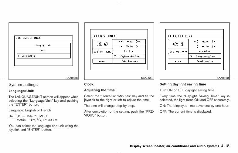
System settingsLanguage/Unit:
The LANGUAGE/UNIT screen will appear whenselecting the “Language/Unit” key and pushingthe “ENTER” button.
Language: English or French
Unit: US — Mile, °F, MPGMetric — km, °C, L/100 km
You can select the language and unit using thejoystick and “ENTER” button.
Clock:
Adjusting the time
Select the “Hours” or “Minutes” key and tilt thejoystick to the right or left to adjust the time.
The time will change step by step.
After completion of the setting, push the “PRE-VIOUS” button.
Setting daylight saving time
Turn ON or OFF daylight saving time.
Every time the “Daylight Saving Time” key isselected, the light turns ON and OFF alternately.
ON: The displayed time advances by one hour.
OFF: The current time is displayed.
SAA0658 SAA0659 SAA0660
Display screen, heater, air conditioner and audio systems 4-15
� 04.8.3/Z50-D/V5.0 �
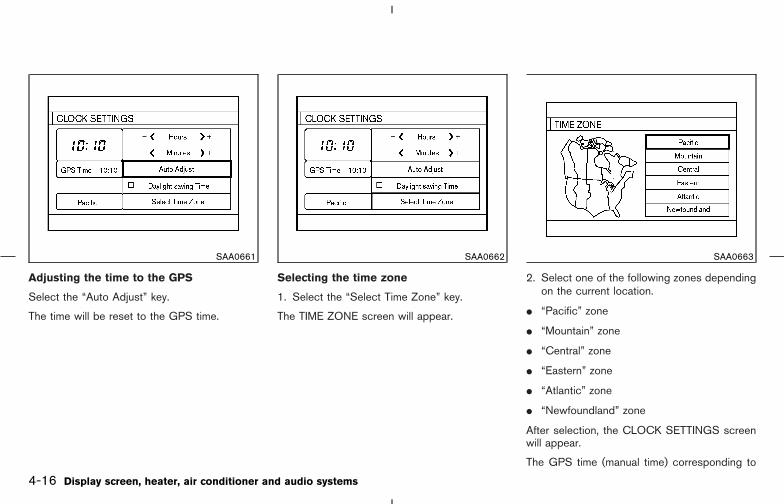
Adjusting the time to the GPS
Select the “Auto Adjust” key.
The time will be reset to the GPS time.
Selecting the time zone
1. Select the “Select Time Zone” key.
The TIME ZONE screen will appear.
2. Select one of the following zones dependingon the current location.
� “Pacific” zone
� “Mountain” zone
� “Central” zone
� “Eastern” zone
� “Atlantic” zone
� “Newfoundland” zone
After selection, the CLOCK SETTINGS screenwill appear.
The GPS time (manual time) corresponding to
SAA0661 SAA0662 SAA0663
4-16 Display screen, heater, air conditioner and audio systems
� 04.8.3/Z50-D/V5.0 �

the selected zone will be displayed.
“Pacific” zone has been set as the initial (default)setting.
Beep setting:
When Beep setting is on (indicator light on), abeep will sound if any audio button is pushed.
“DAY/NIGHT” BUTTONTo change the display brightness, push the“DAY/NIGHT” button. Pushing the button againwill change the display to DAY or NIGHT dis-play. Then, adjust the brightness moving thejoystick right or left.
If no operation is done within 10 seconds, or ifthe “PREV” button is pushed, the display willreturn to the previous display.
When the shift lever is shifted into the R (Re-verse) position, the monitor display shows viewto the rear of the vehicle.
The system is designed as an aid to the driver indetecting large stationary objects to help avoiddamaging the vehicle. The system will not detectsmall objects below the bumper and may notdetect objects close to the bumper or on theground.
WARNING
� The rear view camera is a conve-nience but it is not a substitute forproper backing. Always turn andcheck that it is safe to do so beforebacking up. Always back up slowly.
� Objects viewed in the rear view moni-tor differ from actual distance be-cause a wide-angle lens is used. Ob-jects in the rear view monitor willappear visually opposite like onesviewed in the inside and outside mir-rors.
� Make sure that the back door is se-curely closed when backing up.
� Underneath the bumper and the cor-ner areas of the bumper cannot beviewed on the rear view monitor be-cause of its monitoring range limita-tion.
� Do not put anything on the rear viewcamera. The rear view camera is in-stalled above the license plate.
� When washing the vehicle with high-pressure water, be sure not to sprayit around the camera. Otherwise, wa-ter may enter the camera unit caus-ing water condensation on the lens, amalfunction, fire or an electric shock.
� Do not strike the camera. It is a pre-cision instrument. Otherwise, it maymalfunction or cause damage result-ing in a fire or an electric shock.
CAUTION
There is a plastic cover over the camera.Do not scratch the cover when cleaningdirt or snow from it.
REAR VIEW MONITOR (if soequipped)
Display screen, heater, air conditioner and audio systems 4-17
� 04.8.3/Z50-D/V5.0 �

HOW TO READ THE DISPLAYEDLINESLines which indicate the vehicle clearance anddistances to objects with reference to thebumper line �A are displayed on the monitor.
They are indicated as reference distances toobjects. Displayed lines indicate distances 1.5feet (red) �1 , 3 feet (yellow) �2 , 7 feet (green)�3 and 10 feet (green) �4 from the lower part ofthe bumper line �A .
The vehicle clearance lines are wider thanthe actual clearance.
REAR VIEW MONITOR SETTING
WARNING
Do not adjust the Brightness, Contrast,Tint and Color of the rear view monitorwhile the vehicle is moving. Make surethe parking brake is firmly applied andthe engine is not running.
To adjust the Brightness, Contrast, Tint andColor of the rear view monitor, push the “SET-TING” button with the rear view monitor on,select the item key and adjust the level using thejoystick.
OPERATING TIPS
� When the shift lever is shifted to R, themonitor screen automatically changes to therear view monitor mode. However, the radiocan be heard.
� It may take some time until the rear viewmonitor is displayed after the shift lever hasbeen shifted to R. Objects may be distortedmomentarily until the rear view monitorscreen is displayed completely. When theshift lever is returned to a position other thanR, it may take some time until the screen
changes. Objects on the screen may bedistorted until they are completely displayed.
� When the temperature is extremely high orlow, the screen may not clearly display ob-jects. This is not a malfunction.
� When strong light directly enters the camera,objects may not be displayed clearly.
� Vertical lines may be seen in objects on thescreen. This is due to strong reflected lightfrom the bumper. This is not a malfunction.
� The screen may flicker under fluorescentlight. This is not a malfunction.
� The colors of objects on the rear view monitormay differ somewhat from those of the actualobject.
� When the contrast of objects is low at night,pushing the “ENTER” button may not changethe brightness.
� Objects on the monitor may not be clear in adark place or at night.
� If dirt, rain or snow attaches to the camera,the rear view monitor may not clearly displayobjects. Clean the camera.
� Do not use alcohol, benzine or thinner toclean the camera. This will cause discolora-tion. To clean the camera, wipe with a cloth
SAA0889
4-18 Display screen, heater, air conditioner and audio systems
� 04.8.3/Z50-D/V5.0 �
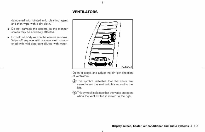
dampened with diluted mild cleaning agentand then wipe with a dry cloth.
� Do not damage the camera as the monitorscreen may be adversely affected.
� Do not use body wax on the camera window.Wipe off any wax with a clean cloth damp-ened with mild detergent diluted with water.
Open or close, and adjust the air flow directionof ventilators.
�A :This symbol indicates that the vents areclosed when the vent switch is moved to theleft.
�B :This symbol indicates that the vents are openwhen the vent switch is moved to the right.
SAA0640
VENTILATORS
Display screen, heater, air conditioner and audio systems 4-19
� 04.8.3/Z50-D/V5.0 �

1. “AUTO” climate control ON button
2. “ ” fresh air button
3. “ ” air recirculation button
4. “ ” front defroster button
5. “ ” rear window defroster switch; referto the “2. Instrument and controls” section.
6. “A/C” air conditioner ON/OFF button
7. “MODE” manual air flow control button
8. Temperature control knob (driver only, ordriver and passenger)
9. “OFF” button for climate control system
10. Fan speed control knob
11. “DUAL” passenger side temperature con-trol ON/OFF button
12. Temperature control knob (passenger side)
SAA0641
HEATER AND AIR CONDITIONER(Automatic)
4-20 Display screen, heater, air conditioner and audio systems
� 04.8.3/Z50-D/V5.0 �
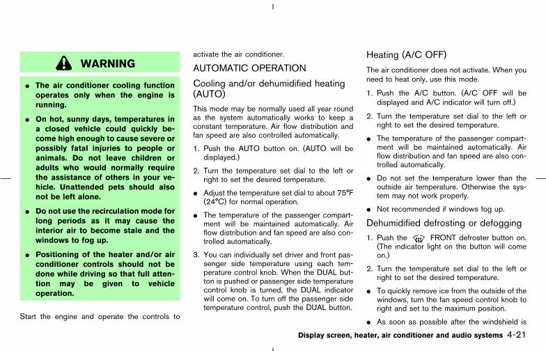
WARNING
� The air conditioner cooling functionoperates only when the engine isrunning.
� On hot, sunny days, temperatures ina closed vehicle could quickly be-come high enough to cause severe orpossibly fatal injuries to people oranimals. Do not leave children oradults who would normally requirethe assistance of others in your ve-hicle. Unattended pets should alsonot be left alone.
� Do not use the recirculation mode forlong periods as it may cause theinterior air to become stale and thewindows to fog up.
� Positioning of the heater and/or airconditioner controls should not bedone while driving so that full atten-tion may be given to vehicleoperation.
Start the engine and operate the controls to
activate the air conditioner.
AUTOMATIC OPERATION
Cooling and/or dehumidified heating(AUTO)This mode may be normally used all year roundas the system automatically works to keep aconstant temperature. Air flow distribution andfan speed are also controlled automatically.
1. Push the AUTO button on. (AUTO will bedisplayed.)
2. Turn the temperature set dial to the left orright to set the desired temperature.
� Adjust the temperature set dial to about 75°F(24°C) for normal operation.
� The temperature of the passenger compart-ment will be maintained automatically. Airflow distribution and fan speed are also con-trolled automatically.
3. You can individually set driver and front pas-senger side temperature using each tem-perature control knob. When the DUAL but-ton is pushed or passenger side temperaturecontrol knob is turned, the DUAL indicatorwill come on. To turn off the passenger sidetemperature control, push the DUAL button.
Heating (A/C OFF)
The air conditioner does not activate. When youneed to heat only, use this mode.
1. Push the A/C button. (A/C OFF will bedisplayed and A/C indicator will turn off.)
2. Turn the temperature set dial to the left orright to set the desired temperature.
� The temperature of the passenger compart-ment will be maintained automatically. Airflow distribution and fan speed are also con-trolled automatically.
� Do not set the temperature lower than theoutside air temperature. Otherwise the sys-tem may not work properly.
� Not recommended if windows fog up.
Dehumidified defrosting or defogging1. Push the FRONT defroster button on.
(The indicator light on the button will comeon.)
2. Turn the temperature set dial to the left orright to set the desired temperature.
� To quickly remove ice from the outside of thewindows, turn the fan speed control knob toright and set to the maximum position.
� As soon as possible after the windshield is
Display screen, heater, air conditioner and audio systems 4-21
� 04.8.3/Z50-D/V5.0 �

clean, push the AUTO button to return to theauto mode.
� When the front defroster button ispushed, the air conditioner will automaticallybe turned on at outside temperatures above23°F (−5°C) to defog the windshield, and theair recirculate mode will automatically beturned off.
Outside air is drawn into the passengercompartment to improve the defogging per-formance.
MANUAL OPERATION
Fan speed controlTurn the fan control button to manuallycontrol the fan speed.
Push the AUTO button to return to automaticcontrol of the fan speed.
Air recirculationPush the air recirculation button to recir-culate interior air inside the vehicle. The indicatorlight on the button will come on.
The air recirculation cannot be activatedwhen the air conditioner is in the front defrostingmode .
Fresh airPush the button to draw outside air intothe passenger compartment. The indicator lighton the button will come on.
Automatic intake air controlIn the AUTO mode, the intake air will be con-trolled automatically. To manually control theintake air, push the air recirculate or freshair button. To return to the automaticcontrol mode, push the indicator-illuminated but-ton for about 2 seconds. The indicator lights(both air recirculate and fresh air buttons) willflash twice, and then the intake air will becontrolled automatically.
Air flow controlPushing the MODE manual air flow controlbutton selects the air outlet to:
: Air flows from center and side ventila-tors.
: Air flows from center and side ventila-tors and foot outlets.
: Air flows from foot outlets and sideventilators.
: Air flows from defroster, foot outletsand side ventilators.
To turn the system offPush the OFF button.
OPERATING TIPSWhen the engine coolant temperature and out-side air temperature are low, the air flow from thefoot outlets may not operate for a maximum of150 seconds. However, this is not a malfunction.After the coolant temperature warms up, the airflow from the foot outlets will operate normally.
4-22 Display screen, heater, air conditioner and audio systems
� 04.8.3/Z50-D/V5.0 �
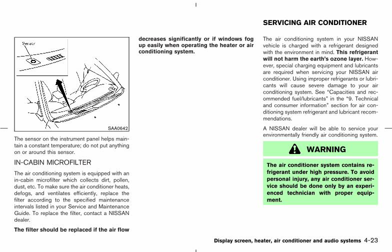
The sensor on the instrument panel helps main-tain a constant temperature; do not put anythingon or around this sensor.
IN-CABIN MICROFILTER
The air conditioning system is equipped with anin-cabin microfilter which collects dirt, pollen,dust, etc. To make sure the air conditioner heats,defogs, and ventilates efficiently, replace thefilter according to the specified maintenanceintervals listed in your Service and MaintenanceGuide. To replace the filter, contact a NISSANdealer.
The filter should be replaced if the air flow
decreases significantly or if windows fogup easily when operating the heater or airconditioning system.
The air conditioning system in your NISSANvehicle is charged with a refrigerant designedwith the environment in mind. This refrigerantwill not harm the earth’s ozone layer. How-ever, special charging equipment and lubricantsare required when servicing your NISSAN airconditioner. Using improper refrigerants or lubri-cants will cause severe damage to your airconditioning system. See “Capacities and rec-ommended fuel/lubricants” in the “9. Technicaland consumer information” section for air con-ditioning system refrigerant and lubricant recom-mendations.
A NISSAN dealer will be able to service yourenvironmentally friendly air conditioning system.
WARNING
The air conditioner system contains re-frigerant under high pressure. To avoidpersonal injury, any air conditioner ser-vice should be done only by an experi-enced technician with proper equip-ment.
SAA0642
SERVICING AIR CONDITIONER
Display screen, heater, air conditioner and audio systems 4-23
� 04.8.3/Z50-D/V5.0 �
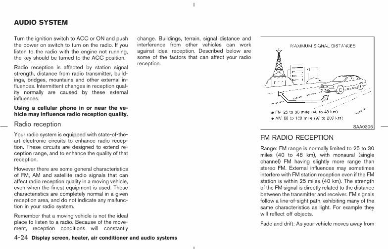
Turn the ignition switch to ACC or ON and pushthe power on switch to turn on the radio. If youlisten to the radio with the engine not running,the key should be turned to the ACC position.
Radio reception is affected by station signalstrength, distance from radio transmitter, build-ings, bridges, mountains and other external in-fluences. Intermittent changes in reception qual-ity normally are caused by these externalinfluences.
Using a cellular phone in or near the ve-hicle may influence radio reception quality.
Radio receptionYour radio system is equipped with state-of-the-art electronic circuits to enhance radio recep-tion. These circuits are designed to extend re-ception range, and to enhance the quality of thatreception.
However there are some general characteristicsof FM, AM and satellite radio signals that canaffect radio reception quality in a moving vehicle,even when the finest equipment is used. Thesecharacteristics are completely normal in a givenreception area, and do not indicate any malfunc-tion in your radio system.
Remember that a moving vehicle is not the idealplace to listen to a radio. Because of the move-ment, reception conditions will constantly
change. Buildings, terrain, signal distance andinterference from other vehicles can workagainst ideal reception. Described below aresome of the factors that can affect your radioreception.
FM RADIO RECEPTION
Range: FM range is normally limited to 25 to 30miles (40 to 48 km), with monaural (singlechannel) FM having slightly more range thanstereo FM. External influences may sometimesinterfere with FM station reception even if the FMstation is within 25 miles (40 km). The strengthof the FM signal is directly related to the distancebetween the transmitter and receiver. FM signalsfollow a line-of-sight path, exhibiting many of thesame characteristics as light. For example theywill reflect off objects.
Fade and drift: As your vehicle moves away from
SAA0306
AUDIO SYSTEM
4-24 Display screen, heater, air conditioner and audio systems
� 04.8.3/Z50-D/V5.0 �

a station transmitter, the signals will tend to fadeand/or drift.
Static and flutter: During signal interference frombuildings, large hills or due to antenna position,usually in conjunction with increased distancefrom the station transmitter, static or flutter canbe heard. This can be reduced by adjusting thetreble control counterclockwise to reduce trebleresponse.
Multipath reception: Because of the reflectivecharacteristics of FM signals, direct and re-flected signals reach the receiver at the sametime. The signals may cancel each other, result-ing in momentary flutter or loss of sound.
AM RADIO RECEPTIONAM signals, because of their low frequency, canbend around objects and skip along the ground.In addition, the signals can be bounced off theionosphere and bent back to earth. Because ofthese characteristics, AM signals are also sub-ject to interference as they travel from transmitterto receiver.
Fading: Occurs while the vehicle is passingthrough freeway underpasses or in areas withmany tall buildings. It can also occur for severalseconds during ionospheric turbulence even inareas where no obstacles exist.
Static: Caused by thunderstorms, electrical
power lines, electric signs and even traffic lights.
SATELLITE RADIO RECEPTION
When the satellite radio is first installed or thebattery has been replaced, the satellite radiomay not work properly. This is not a malfunction.Wait more than 10 minutes with satellite radioON for satellite radio to receive all of the neces-sary data.
No satellite radio reception is available and “NOSAT” will be displayed when the SAT button ispushed unless the optional satellite receiver andantenna were factory installed (late availabilityonly/retrofit unavailable), and an XM or SIRI-USTM satellite radio service subscription is ac-tive.
Satellite radio performance may be effected ifcargo carried on the roof rack blocks the satelliteradio signal.
If possible, do not put cargo over the satelliteradio antenna.
AUDIO OPERATION PRECAUTIONS
Cassette player
� To maintain good quality sound,NISSAN recommends using cassettetapes of 60 minutes or shorter in length.
� Cassette tapes should be removed fromthe player when not in use. Store cas-settes in their protective cases andaway from direct sunlight, heat, dust,moisture and magnetic sources.
� Direct sunlight can cause the cassette tobecome deformed. The use of deformedcassettes may cause the cassette to jamin the player.
� Do not use cassettes with labels whichare peeling and loose. If used, the labelcould jam in the player.
� If a cassette has loose tape, insert apencil through one of the cassette hubsand rewind the tape firmly around thehubs. Loose tape may cause tape jam-ming and wavering sound quality.
� Over a period of time, the playbackhead, capstan and pinch roller may col-lect a tape coating residue as the tape isplayed. This residue accumulation cancause weak or wavering sound, andshould be removed periodically with ahead cleaning tape. If the residue is notremoved periodically, the player mayneed to be disassembled for cleaning.
Display screen, heater, air conditioner and audio systems 4-25
� 04.8.3/Z50-D/V5.0 �

Compact Disc (CD) player
� Only use high quality 4.7 inches (12 cm)round discs that have the “COMPACTdisc DIGITAL AUDIO” logo on the disc orpackaging.
� During cold weather or rainy days, theplayer may malfunction due to the hu-midity. If this occurs, remove the CD anddehumidify or ventilate the player com-pletely.
� The player may skip while driving onrough roads.
� The CD player sometimes cannot func-tion when the compartment tempera-ture is extremely high. Decrease thetemperature before use.
� Do not expose the CD to direct sunlight.
� CDs that are of poor quality, dirty,scratched, covered with fingerprints, orthat have pin holes may not work prop-erly.
� The following CDs may not work prop-erly:
• Copy control compact discs (CCCD)
• Recordable compact discs (CD-R)
• Rewritable compact discs (CD-RW)
� Do not use the following CDs as theymay cause the CD player to malfunction.
• 3.1 in (8 cm) discs with an adapter
• CDs that are not round
• CDs with a paper label
• CDs that are warped, scratched, orhave abnormal edges
SAA0480
4-26 Display screen, heater, air conditioner and audio systems
� 04.8.3/Z50-D/V5.0 �
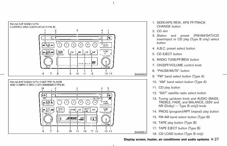
1. SEEK/APS REW, APS FF/TRACKCHANGE button
2. CD slot3. Station and preset (FM/AM/SAT)/CD
insert/eject or CD play (Type B only) selectbutton
4. A.B.C. preset select button
5. CD EJECT button
6. RADIO TUNE/FF⋅REW button
7. ON⋅OFF/VOLUME control knob
8. “PAUSE/MUTE” button
9. “FM” band select button (Type A)
10. “AM” band select button (Type A)
11. CD play button
12. “SAT” satellite radio select button
13. Tuning up/down knob and AUDIO (BASS,TREBLE, FADE, and BALANCE, (SSV andNR (Dolby) — Type B only)) knob
14. PROG (program)/RPT (repeat) play button
15. FM-AM band select button (Type B)
16. TAPE play button (Type B)
17. TAPE EJECT button (Type B)
18. CD LOAD button (Type B only)
SAA0650
SAA0651
Display screen, heater, air conditioner and audio systems 4-27
� 04.8.3/Z50-D/V5.0 �

FM-AM-SAT RADIO WITHCASSETTE PLAYER ANDCOMPACT DISC (CD) PLAYER(TYPE A)/CD CHANGER (TYPE B)
No satellite radio reception is available and “NOSAT” will be displayed when the SAT button ispushed unless the optional satellite receiver andantenna were factory installed (late availabilityonly/retrofit unavailable), and an XM or SIRI-USTM satellite radio service subscription is ac-tive.
Audio main operation
The tape deck (type B) employs a permalloyhead which allows for improved reproduction ofhigh frequency ranges. Noise is also greatlyreduced by the combined use of the Dolby NR(Noise Reduction) system. The auto loudnesscircuit enhances the low frequency range auto-matically in both radio reception and tape andCD playback.
ON⋅OFF/Volume control:
Turn the ignition switch to ACC or ON, and thenpush the ON⋅OFF/Volume control knob whilethe system is off to call up the mode (radio, tapeor CD) which was playing immediately beforethe system was turned off. When no CD or tapeis loaded, the radio will come on. While the
system is on, pushing the ON⋅OFF/Volume con-trol knob turns the system off.
To turn the radio off, push the Power/Volumecontrol knob.
Turn the ON⋅OFF/Volume control knob to adjustthe volume.
This vehicle has Speed Sensitive control Vol-ume (SSV) for audio (type B only). The audiovolume changes as the driving speed changes.
AUDIO knob (BASS, TREBLE, FADE,BALANCE, (SSV and NR (Dolby) — type Bonly)):
Push the AUDIO knob to change the selectingmode as follows.
BASS → TREBLE → FADE → BALANCE →SSV (type B only) → NR (when cassette playingtype B only)
To adjust BASS, Treble, Fader and Balance,push the AUDIO knob until the desired modeBASS, TREBLE, FADE or BALANCE appears inthe display. Turn the Tuning knob to adjust Bassand Treble to the desired level. Use the Tuningknob also to adjust Fader or Balance modes.Fader adjusts the sound level between the frontand rear speakers and Balance adjusts thesound between the right and left speakers.
To change the SSV mode to OFF, LOW, MID or
HIGH, turn the Tuning knob to right or left. (typeB only).
To change the NR (Dolby) mode to OFF or ON,turn the Tuning knob to right or left while cas-sette tape is playing. When Dolby is ON, thedisplay indicates the mark. (type B only)
Dolby noise reduction is manufactured underlicense from Dolby Laboratories Licensing Cor-poration. Dolby NR and the double-D symbol“ ” are trademarks of Dolby LaboratoriesLicensing Corporation.
After 10 seconds, the radio, cassette tape or CDdisplay reappears. Once the sound quality is setto the desired level, push the AUDIO buttonrepeatedly until the radio, cassette tape or CDdisplay appears.
Display CD text:
To indicate the CD mode text, push the AUDIOknob during CD playing.
Track No. → Track title → Disc title → BASS →TREBLE → FADE → BALANCE → SSV →Display mode
To change the indicated text in display mode,turn the tuning knob within 2 seconds.
The text will change as follows:
4-28 Display screen, heater, air conditioner and audio systems
� 04.8.3/Z50-D/V5.0 �

Display satellite radio text:
To indicate the satellite mode text, push theAUDIO knob during satellite radio play.
Artist → Title → BASS → TREBLE → FADE →BALANCE → SSV → Display mode
To change the indicated text in display mode,turn the tuning knob within 2 seconds.
Pause/mute button:
To mute or pause the audio sound, push thePAUSE/MUTE button.
To release the mute or pause, push the buttonagain.
FM-AM-SAT radio operationor SAT FM/AM/SAT radio
select:
No satellite radio reception is available and “NOSAT” will be displayed when the SAT button ispushed unless the optional satellite receiver andantenna were factory installed (late availability
only/retrofit unavailable), and an XM or SIRI-USTM satellite radio service subscription is ac-tive.
Pushing the FM/AM (Type B), FM, AM (Type A)or SAT band select button will change the bandas follows:
AM ↔ FM or SAT (Satellite)
When FM/AM/SAT radio select button ispushed while the ignition switch is in the ACC orON, the radio will come on at the station lastplayed.
The last station played will also come on whenthe power knob is turned to ON.
If a compact disc or tape is playing when theFM/AM/SAT radio select button is turned to ON,the compact disc or tape will automatically beturned off and the last radio station played willcome on.
The FM stereo indicator ST will glow during FMstereo reception. When the stereo broadcastsignal is weak, the radio will automaticallychange from stereo to monaural reception.
TUNE (Tuning):
WARNING
The radio should not be tuned whiledriving so full attention may be given tovehicle operation.
To tune the radio, push the RADIO TUNE button( or ) or turn the Tuning knob to rightor left.
Use these buttons for manual tuning. To movequickly through the channels, hold either of theRADIO TUNE buttons down for more than 1.5seconds.
SEEK/SCAN tuning:
Push the SEEK button or for lessthan 1.5 seconds, to tune from high to low or lowto high frequencies and stops at the next broad-casting station.
Push the or SEEK button for morethan 1.5 seconds to tune from low to highfrequencies and stops at each broadcastingstation for 5 seconds. Pushing the button againduring this 5 seconds period will stop SCANtuning and the radio will remain tuned to thatstation.
Display screen, heater, air conditioner and audio systems 4-29
� 04.8.3/Z50-D/V5.0 �
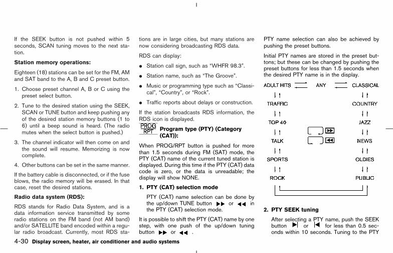
If the SEEK button is not pushed within 5seconds, SCAN tuning moves to the next sta-tion.
Station memory operations:
Eighteen (18) stations can be set for the FM, AMand SAT band to the A, B and C preset button.
1. Choose preset channel A, B or C using thepreset select button.
2. Tune to the desired station using the SEEK,SCAN or TUNE button and keep pushing anyof the desired station memory buttons (1 to6) until a beep sound is heard. (The radiomutes when the select button is pushed.)
3. The channel indicator will then come on andthe sound will resume. Memorizing is nowcomplete.
4. Other buttons can be set in the same manner.
If the battery cable is disconnected, or if the fuseblows, the radio memory will be erased. In thatcase, reset the desired stations.
Radio data system (RDS):
RDS stands for Radio Data System, and is adata information service transmitted by someradio stations on the FM band (not AM band)and/or SATELLITE band encoded within a regu-lar radio broadcast. Currently, most RDS sta-
tions are in large cities, but many stations arenow considering broadcasting RDS data.
RDS can display:
� Station call sign, such as “WHFR 98.3”.
� Station name, such as “The Groove”.
� Music or programming type such as “Classi-cal”, “Country”, or “Rock”.
� Traffic reports about delays or construction.
If the station broadcasts RDS information, theRDS icon is displayed.
Program type (PTY) (Category(CAT)):
When PROG/RPT button is pushed for morethan 1.5 seconds during FM (SAT) mode, thePTY (CAT) name of the current tuned station isdisplayed. During this time if the PTY (CAT) datacode is zero, or the data is unreadable; thedisplay will show NONE.
1. PTY (CAT) selection mode
PTY (CAT) name selection can be done bythe up/down TUNE button or inthe PTY (CAT) selection mode.
It is possible to shift the PTY (CAT) name by onestep, with one push of the up/down tuningbutton or .
PTY name selection can also be achieved bypushing the preset buttons.
Initial PTY names are stored in the preset but-tons; but these can be changed by pushing thepreset buttons for less than 1.5 seconds whenthe desired PTY name is in the display.
2. PTY SEEK tuning
After selecting a PTY name, push the SEEKbutton or for less than 0.5 sec-onds within 10 seconds. Tuning to the PTY
4-30 Display screen, heater, air conditioner and audio systems
� 04.8.3/Z50-D/V5.0 �
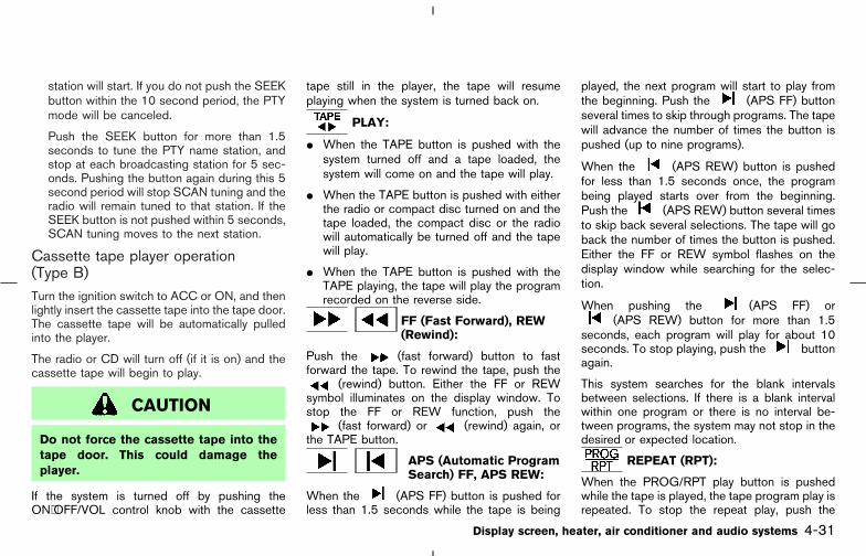
station will start. If you do not push the SEEKbutton within the 10 second period, the PTYmode will be canceled.
Push the SEEK button for more than 1.5seconds to tune the PTY name station, andstop at each broadcasting station for 5 sec-onds. Pushing the button again during this 5second period will stop SCAN tuning and theradio will remain tuned to that station. If theSEEK button is not pushed within 5 seconds,SCAN tuning moves to the next station.
Cassette tape player operation(Type B)Turn the ignition switch to ACC or ON, and thenlightly insert the cassette tape into the tape door.The cassette tape will be automatically pulledinto the player.
The radio or CD will turn off (if it is on) and thecassette tape will begin to play.
CAUTION
Do not force the cassette tape into thetape door. This could damage theplayer.
If the system is turned off by pushing theON⋅OFF/VOL control knob with the cassette
tape still in the player, the tape will resumeplaying when the system is turned back on.
PLAY:
� When the TAPE button is pushed with thesystem turned off and a tape loaded, thesystem will come on and the tape will play.
� When the TAPE button is pushed with eitherthe radio or compact disc turned on and thetape loaded, the compact disc or the radiowill automatically be turned off and the tapewill play.
� When the TAPE button is pushed with theTAPE playing, the tape will play the programrecorded on the reverse side.
FF (Fast Forward), REW(Rewind):
Push the (fast forward) button to fastforward the tape. To rewind the tape, push the
(rewind) button. Either the FF or REWsymbol illuminates on the display window. Tostop the FF or REW function, push the
(fast forward) or (rewind) again, orthe TAPE button.
APS (Automatic ProgramSearch) FF, APS REW:
When the (APS FF) button is pushed forless than 1.5 seconds while the tape is being
played, the next program will start to play fromthe beginning. Push the (APS FF) buttonseveral times to skip through programs. The tapewill advance the number of times the button ispushed (up to nine programs).
When the (APS REW) button is pushedfor less than 1.5 seconds once, the programbeing played starts over from the beginning.Push the (APS REW) button several timesto skip back several selections. The tape will goback the number of times the button is pushed.Either the FF or REW symbol flashes on thedisplay window while searching for the selec-tion.
When pushing the (APS FF) or(APS REW) button for more than 1.5
seconds, each program will play for about 10seconds. To stop playing, push the buttonagain.
This system searches for the blank intervalsbetween selections. If there is a blank intervalwithin one program or there is no interval be-tween programs, the system may not stop in thedesired or expected location.
REPEAT (RPT):
When the PROG/RPT play button is pushedwhile the tape is played, the tape program play isrepeated. To stop the repeat play, push the
Display screen, heater, air conditioner and audio systems 4-31
� 04.8.3/Z50-D/V5.0 �

PROG/RPT play button again.
Metal or chrome tape usage:The cassette player will be automatically set tohigh performance play when playing a metal orchrome cassette tape.
TAPE EJECT:
When this button is pushed with the tapeloaded, the tape will be ejected.When the tape is ejected while it is being played,the system will be turned off.
Compact disc (CD) player operation(Type A)Turn the ignition switch to the ACC or ONposition and insert the compact disc into the slotwith the label side facing up. The compact discwill be guided automatically into the slot andstart playing.After loading the disc, the number of tracks onthe disc and the play time will appear on thedisplay.If the radio or tape is already operating, it willautomatically turn off and the compact disc willplay.
CAUTION
Do not force the compact disc into theslot. This could damage the player.
If the system has been turned off while thecompact disc was playing, pushing theON⋅OFF/VOL control knob will start the com-pact disc.
8 cm diameter compact discs can be usedwithout an adapter.
PLAY:
When the CD button is pushed with the systemoff and the compact disc loaded, the system willturn on and the compact disc will start to play.
When the CD button is pushed with the com-pact disc loaded but the tape or the radioplaying, the tape or radio will automatically beturned off and the compact disc will start to play.
FF (Fast Forward), REW(Rewind):
When the (fast forward) or (rewind)button is pushed while the compact disc isbeing played, the compact disc will play whilefast forwarding or rewinding. When the button is
released, the compact disc will return to normalplay speed.
APS (Automatic ProgramSearch) FF, APS REW:
When the (APS FF) button is pushed forless than 1.5 seconds while the compact disc isbeing played, the program next to the presentone will start to play from its beginning. Pushseveral times to skip through programs. Thecompact disc will advance the number of timesthe button is pushed. (When the last program onthe compact disc is skipped through, the firstprogram will be played.) When the (APSREW) button is pushed for less than 1.5 sec-onds, the program being played returns to itsbeginning. Push several times to skip backthrough programs. The compact disc will goback the number of times the button is pushed.
When pushing the (APS FF) or(APS REW) button for more than 1.5
seconds, each track will play for about 10seconds. To stop playing, push the buttonagain.
REPEAT (RPT):
When the PROG/RPT play button is pushedwhile the compact disc is being played, the playpattern can be changed as follows:
4-32 Display screen, heater, air conditioner and audio systems
� 04.8.3/Z50-D/V5.0 �
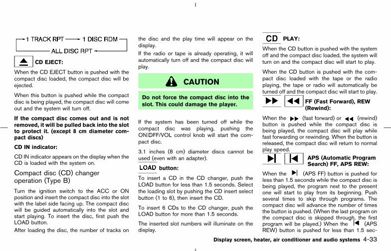
CD EJECT:
When the CD EJECT button is pushed with thecompact disc loaded, the compact disc will beejected.
When this button is pushed while the compactdisc is being played, the compact disc will comeout and the system will turn off.
If the compact disc comes out and is notremoved, it will be pulled back into the slotto protect it. (except 8 cm diameter com-pact discs)
CD IN indicator:
CD IN indicator appears on the display when theCD is loaded with the system on.
Compact disc (CD) changeroperation (Type B)Turn the ignition switch to the ACC or ONposition and insert the compact disc into the slotwith the label side facing up. The compact discwill be guided automatically into the slot andstart playing. To insert the disc, first push theLOAD button.After loading the disc, the number of tracks on
the disc and the play time will appear on thedisplay.If the radio or tape is already operating, it willautomatically turn off and the compact disc willplay.
CAUTION
Do not force the compact disc into theslot. This could damage the player.
If the system has been turned off while thecompact disc was playing, pushing theON⋅OFF/VOL control knob will start the com-pact disc.
3.1 inches (8 cm) diameter discs cannot beused (even with an adapter).
button:
To insert a CD in the CD changer, push theLOAD button for less than 1.5 seconds. Selectthe loading slot by pushing the CD insert selectbutton (1 to 6), then insert the CD.
To insert 6 CDs to the CD changer, push theLOAD button for more than 1.5 seconds.
The inserted slot numbers will illuminate on thedisplay.
PLAY:
When the CD button is pushed with the systemoff and the compact disc loaded, the system willturn on and the compact disc will start to play.
When the CD button is pushed with the com-pact disc loaded with the tape or the radioplaying, the tape or radio will automatically beturned off and the compact disc will start to play.
FF (Fast Forward), REW(Rewind):
When the (fast forward) or (rewind)button is pushed while the compact disc isbeing played, the compact disc will play whilefast forwarding or rewinding. When the button isreleased, the compact disc will return to normalplay speed.
APS (Automatic ProgramSearch) FF, APS REW:
When the (APS FF) button is pushed forless than 1.5 seconds while the compact disc isbeing played, the program next to the presentone will start to play from its beginning. Pushseveral times to skip through programs. Thecompact disc will advance the number of timesthe button is pushed. (When the last program onthe compact disc is skipped through, the firstprogram will be played.) When the (APSREW) button is pushed for less than 1.5 sec-
Display screen, heater, air conditioner and audio systems 4-33
� 04.8.3/Z50-D/V5.0 �

onds, the program being played returns to itsbeginning. Push several times to skip backthrough programs. The compact disc will goback the number of times the button is pushed.
When pushing the (APS FF) or(APS REW) button for more than 1.5
seconds, each track will play for about 10seconds. To stop playing, push the buttonagain.
CD PLAY button:
To change CD, push the CD play select button(1 to 6). You can select if the CD is inserted.
REPEAT (RPT):
When the PROG/RPT play button is pushedwhile the compact disc is played, the playpattern can be changed as follows:
CD EJECT:
When the CD EJECT button is pushed with thecompact disc loaded, the compact disc will beejected.
To eject the selected discs by the EJECT button,push it for less than 1.5 seconds.
To eject all the discs, push the EJECT button for
more than 1.5 seconds.
When this button is pushed while the compactdisc is being played, the compact disc will comeout and the system will turn off.
If the compact disc comes out and is notremoved, it will be pulled back into the slotto protect it.
CD IN indicator:
CD IN indicator appears on the display when theCD is loaded with the system on.
CD CARE AND CLEANING� Handle a CD by its edges. Never touch the
surface of the disc. Do not bend the disc.� Always place the discs in the storage case
when they are not being used.� To clean a disc, wipe the surface from the
center to the outer edge using a clean, softcloth. Do not wipe the disc using a circularmotion.Do not use a conventional record cleaner oralcohol intended for industrial use.
� A new disc may be rough on its inner andouter edges. Remove the rough edges usingthe side of a pen or pencil as illustrated.
SAA0451
4-34 Display screen, heater, air conditioner and audio systems
� 04.8.3/Z50-D/V5.0 �
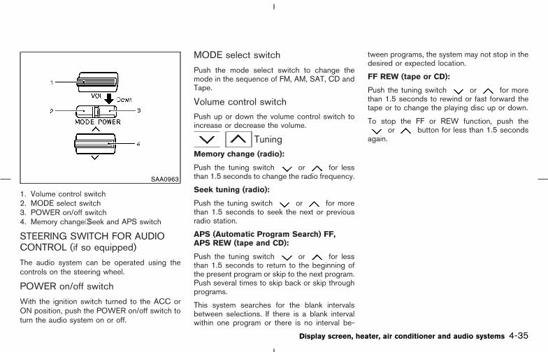
1. Volume control switch2. MODE select switch3. POWER on/off switch4. Memory change⋅Seek and APS switch
STEERING SWITCH FOR AUDIOCONTROL (if so equipped)
The audio system can be operated using thecontrols on the steering wheel.
POWER on/off switch
With the ignition switch turned to the ACC orON position, push the POWER on/off switch toturn the audio system on or off.
MODE select switch
Push the mode select switch to change themode in the sequence of FM, AM, SAT, CD andTape.
Volume control switchPush up or down the volume control switch toincrease or decrease the volume.
TuningMemory change (radio):
Push the tuning switch or for lessthan 1.5 seconds to change the radio frequency.
Seek tuning (radio):
Push the tuning switch or for morethan 1.5 seconds to seek the next or previousradio station.
APS (Automatic Program Search) FF,APS REW (tape and CD):
Push the tuning switch or for lessthan 1.5 seconds to return to the beginning ofthe present program or skip to the next program.Push several times to skip back or skip throughprograms.
This system searches for the blank intervalsbetween selections. If there is a blank intervalwithin one program or there is no interval be-
tween programs, the system may not stop in thedesired or expected location.
FF REW (tape or CD):
Push the tuning switch or for morethan 1.5 seconds to rewind or fast forward thetape or to change the playing disc up or down.
To stop the FF or REW function, push theor button for less than 1.5 seconds
again.
SAA0963
Display screen, heater, air conditioner and audio systems 4-35
� 04.8.3/Z50-D/V5.0 �
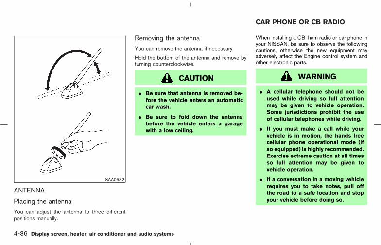
ANTENNA
Placing the antenna
You can adjust the antenna to three differentpositions manually.
Removing the antennaYou can remove the antenna if necessary.
Hold the bottom of the antenna and remove byturning counterclockwise.
CAUTION
� Be sure that antenna is removed be-fore the vehicle enters an automaticcar wash.
� Be sure to fold down the antennabefore the vehicle enters a garagewith a low ceiling.
When installing a CB, ham radio or car phone inyour NISSAN, be sure to observe the followingcautions, otherwise the new equipment mayadversely affect the Engine control system andother electronic parts.
WARNING
� A cellular telephone should not beused while driving so full attentionmay be given to vehicle operation.Some jurisdictions prohibit the useof cellular telephones while driving.
� If you must make a call while yourvehicle is in motion, the hands freecellular phone operational mode (ifso equipped) is highly recommended.Exercise extreme caution at all timesso full attention may be given tovehicle operation.
� If a conversation in a moving vehiclerequires you to take notes, pull offthe road to a safe location and stopyour vehicle before doing so.
SAA0532
CAR PHONE OR CB RADIO
4-36 Display screen, heater, air conditioner and audio systems
� 04.8.3/Z50-D/V5.0 �

CAUTION
� Keep the antenna as far as possibleaway from the electronic controlmodules.
� Keep the antenna wire more than 8 in(20 cm) away from the electronic con-trol system harnesses. Do not routethe antenna wire next to any harness.
� Adjust the antenna standing-waveratio as recommended by the manu-facturer.
� Connect the ground wire from the CBradio chassis to the body.
� For details, consult a NISSAN dealer.
Display screen, heater, air conditioner and audio systems 4-37
� 04.8.3/Z50-D/V5.0 �

MEMO
4-38 Display screen, heater, air conditioner and audio systems
� 04.8.3/Z50-D/V5.0 �
5 Starting and driving
Precautions when starting and driving ............................. 5-2Exhaust gas (Carbon monoxide) .................................. 5-2Three-way catalyst ........................................................... 5-3Low tire pressure warning system(if so equipped) ................................................................ 5-3Avoiding collision and rollover ...................................... 5-5On-pavement and offroad driving precautions(AWD)................................................................................. 5-5Drinking alcohol/drugs and driving.............................. 5-5Driving safety precautions.............................................. 5-6
Ignition switch (Except for Intelligent Key equippedmodel) ....................................................................................... 5-8
Key positions..................................................................... 5-9NISSAN Vehicle Immobilizer System (NVIS)............ 5-9
Ignition switch (Intelligent Key System equippedmodel)..................................................................................... 5-10
Ignition switch positions .............................................. 5-10NISSAN Vehicle Immobilizer System (NVIS) ......... 5-11
Before starting the engine ................................................ 5-11Starting the engine ............................................................. 5-12Driving the vehicle............................................................... 5-12
CVT (Continuously Variable Transmission)............. 5-12M-CVT (CVT with Manual shift mode)..................... 5-16
Parking brake........................................................................ 5-20
Cruise control....................................................................... 5-21Precautions on cruise control .................................... 5-21Cruise control operations ............................................ 5-21
Break-in schedule .............................................................. 5-23Increasing fuel economy.................................................... 5-23Using all wheel drive (AWD) (if so equipped)............. 5-24
AWD lock switch operations...................................... 5-24AWD warning light........................................................ 5-26
Parking/parking on hills...................................................... 5-28Power steering ..................................................................... 5-29Brake system........................................................................ 5-29
Braking precautions ...................................................... 5-29Anti-lock brake system (ABS).................................... 5-30
Vehicle dynamic control (VDC) system(if so equipped) .................................................................. 5-31Cold weather driving .......................................................... 5-33
Freeing a frozen door lock .......................................... 5-33Antifreeze ......................................................................... 5-33Battery .............................................................................. 5-33Draining of coolant water ............................................ 5-33Tire equipment................................................................ 5-33Special winter equipment............................................ 5-34Driving on snow or ice ................................................. 5-34Engine block heater (if so equipped)....................... 5-34
� 04.8.3/Z50-D/V5.0 �
WARNING
� Do not leave children or adults whowould normally require the supportof others alone in your vehicle. Petsshould not be left alone either. Theycould accidentally injure themselvesor others through inadvertent opera-tion of the vehicle. Also, on hot,sunny days, temperatures in a closedvehicle could quickly become highenough to cause severe or possiblyfatal injuries to people or animals.
� Properly secure all cargo to help pre-vent it from sliding or shifting. Do notplace cargo higher than the seat-backs. In a sudden stop or collision,unsecured cargo could cause per-sonal injury.
EXHAUST GAS (Carbon monoxide)
WARNING
Do not breathe exhaust gases; they con-
tain colorless and odorless carbon mon-oxide. Carbon monoxide is dangerous.It can cause unconsciousness or death.
� If you suspect that exhaust fumes areentering the vehicle, drive with allwindows fully open, and have thevehicle inspected immediately.
� Do not run the engine in closedspaces such as a garage.
� Do not park the vehicle with the en-gine running for any extended lengthof time.
� Keep the back door closed while driv-ing, otherwise exhaust gases couldbe drawn into the passenger com-partment. If you must drive with theback door open, follow these precau-tions:
1. Open all the windows.
2. Set the air recirculation switchOFF and the fan control at 4 (high)to circulate the air.
� If electrical wiring or other cable con-
nections must pass to a trailerthrough the seal on the back door orthe body, follow the manufacturer’srecommendation to prevent carbonmonoxide entry into the vehicle.
� If a special body, camper or otherequipment is added for recreationalor other usage, follow the manufac-turer’s recommendation to preventcarbon monoxide entry into the ve-hicle. (Some recreational vehicle ap-pliances such as stoves, refrigera-tors, heaters, etc. may also generatecarbon monoxide.)
� The exhaust system and body shouldbe inspected by a qualified mechanicwhenever:
a. The vehicle is raised for service.
b. You suspect that exhaust fumesare entering into the passengercompartment.
c. You notice a change in the soundof the exhaust system.
PRECAUTIONS WHEN STARTINGAND DRIVING
5-2 Starting and driving
� 04.8.3/Z50-D/V5.0 �

d. You have had an accident involv-ing damage to the exhaust system,underbody, or rear of the vehicle.
THREE-WAY CATALYSTThe three-way catalyst is an emission controldevice installed in the exhaust system. Exhaustgases in the converter are burned at high tem-peratures to help reduce pollutants.
WARNING
� The exhaust gas and the exhaust sys-tem are very hot. Keep people, ani-mals or flammable materials awayfrom the exhaust system compo-nents.
� Do not stop or park the vehicle overflammable materials such as drygrass, waste paper or rags. They mayignite and cause a fire.
CAUTION
� Do not use leaded gasoline. Depositsfrom leaded gasoline will seriouslyreduce the three-way catalyst’s abil-ity to help reduce exhaust pollutants.
� Keep your engine tuned up. Malfunc-tions in the ignition, fuel injection, orelectrical systems can cause overrichfuel flow into the three-way catalyst,causing it to overheat. Do not keepdriving if the engine misfires, or ifnoticeable loss of performance orother unusual operating conditionsare detected. Have the vehicle in-spected promptly by a NISSANdealer.
� Avoid driving with an extremely lowfuel level. Running out of fuel couldcause the engine to misfire, damag-ing the three-way catalyst.
� Do not race the engine while warm-ing it up.
� Do not push or tow your vehicle tostart the engine.
LOW TIRE PRESSURE WARNINGSYSTEM (if so equipped)This vehicle is equipped with the low tire pres-sure warning system. It monitors tire pressure ofall tires except the spare. When the low tirepressure warning light is lit, one or more of yourtires is significantly underinflated. The systemalso displays pressure of all tires (except thespare tire) on the display screen by sending asignal from a sensor that is installed in eachwheel.
The low tire pressure warning system will acti-vate only when the vehicle is driven at speedsabove 20 MPH (32 km/h). Also, this system maynot detect a sudden drop in tire pressure (forexample, a flat tire while driving).
Tire pressure rises and falls depending on theheat caused by the vehicle’s operation and theoutside temperature. Low outside temperaturecan lower the temperature of the air inside thetire which can cause a lower tire inflation pres-sure. This may cause the low tire pressurewarning light to illuminate.
If the warning light illuminates in low ambienttemperatures as described above, check the tirepressure for all four tires. Adjust the tire pressureto the recommended COLD tire pressure shownon the Tire and Loading Information label to turnthe low tire pressure warning light OFF.
Starting and driving 5-3
� 04.8.3/Z50-D/V5.0 �

Frequently check the tire pressure informationdisplay on the display screen and adjust pres-sure of each tire properly. (The order of the tirepressure figures displayed on the screen doesnot correspond with the actual order of the tireposition.) See “Tire pressure information” in the“4. Display screen, heater, air conditioner andaudio systems” section for tire pressure monitor.
Low tire pressure warning
If the vehicle is being driven with an extremelylow tire pressure (lower than 27 psi, 190 kPa),the low tire pressure warning light comes on,and the chime sounds for about 10 seconds.
For additional information regarding the abovewarning, see “Warning/indicator lights and au-dible reminders” in the “2. Instruments andcontrols” section.
WARNING
� If the low tire pressure warning lightflashes while driving, avoid suddensteering maneuvers or abrupt brak-ing, reduce vehicle speed, pull off theroad to a safe location and stop thevehicle as soon as possible. Serious
vehicle damage could occur and maylead to an accident and could resultin serious personal injury. Check thetire pressure for all four tires. Adjustthe tire pressure to the recom-mended COLD tire pressure shownon the Tire and Loading Informationlabel to turn the low tire pressurewarning light OFF. If the light stillcomes on while driving after adjust-ing the tire pressure, a tire may beflat. If you have a flat tire, replace itwith a spare tire as soon as possible.(See “Flat tire” in the “In case ofemergency” section for changing aflat tire.)
� When a spare tire is mounted or awheel is replaced, the tire pressure ofthat tire will not be indicated and thelow tire pressure warning system willnot function. Contact a NISSANdealer as soon as possible for tirereplacement and/or system reset-ting.
� Do not inject any tire liquid or aerosoltire sealant into the tires, as this may
cause a malfunction of the tire pres-sure sensors.
CAUTION
Do not place metalized film or any metalparts (antenna, etc.) on the windows.This may cause poor reception of thesignals from the tire pressure sensors,and the low tire pressure warning sys-tem will not function properly.
FCC Notice:Changes or modifications not expresslyapproved by the manufacturer compliancecould void the user’s authority to operatethe equipment.
This device complies with Part 15 of theFCC Rules and RSS-210 of IndustryCanada.
Operation is subject to the following twoconditions: (1) This device may not causeharmful interference, and (2) this devicemust accept any interference received, in-cluding interference that may cause undes-ired operation of the device.
5-4 Starting and driving
� 04.8.3/Z50-D/V5.0 �
AVOIDING COLLISION ANDROLLOVER
WARNING
Failure to operate this vehicle in a safeand prudent manner may result in lossof control or an accident.
Be alert and drive defensively at all times. Obeyall traffic regulations. Avoid excessive speed,high speed cornering, or sudden steering ma-neuvers, because these driving practices couldcause you to lose control of your vehicle. Aswith any vehicle, a loss of control couldresult in a collision with other vehicles orobjects, or cause the vehicle to rollover,particularly if the loss of control causes thevehicle to slide sideways. Be attentive at alltimes, and avoid driving when tired. Never drivewhen under the influence of alcohol or drugs(including prescription or over-the-counterdrugs which may cause drowsiness). Alwayswear your seat belt. See “Seat belts” in the “1.Safety — seats, seat belts and supplementalrestraint system” section. Also instruct your pas-sengers to do so.
Seat belts help reduce the risk of injury incollisions and rollovers. In a rollover crash, an
unbelted or improperly belted person issignificantly more likely to be injured orkilled than a person properly wearing aseat belt.
ON-PAVEMENT AND OFFROADDRIVING PRECAUTIONS (AWD)
Utility vehicles have a significantly higherrollover rate than other types of vehicles.
They have higher ground clearance than passen-ger cars to make them capable of performing ina variety of on-pavement and offroad applica-tions. This gives them a higher center of gravitythan ordinary cars. An advantage of higherground clearance is a better view of the road,allowing you to anticipate problems. However,they are not designed for cornering at the samespeeds as conventional two-wheel drive ve-hicles any more than low-slung sports cars aredesigned to perform satisfactorily under offroadconditions. If at all possible, avoid sharp turns orabrupt maneuvers, particularly at high speeds.As with other vehicles of this type, failure tooperate this vehicle correctly may result in lossof control or vehicle rollover. Seat belts helpreduce the risk of injury in collisions and roll-overs. In a rollover crash, an unbelted or improp-erly belted person is significantly more likely tobe injured or killed than a person properly wear-ing a seat belt.
Be sure to read the driving safety precautionslater in this section.
DRINKING ALCOHOL/DRUGS ANDDRIVING
WARNING
Never drive under the influence of alco-hol or drugs. Alcohol in the bloodstreamreduces coordination, delays reactiontime and impairs judgement. Driving af-ter drinking alcohol increases the likeli-hood of being involved in an accidentinjuring yourself and others. Addition-ally, if you are injured in an accident,alcohol can increase the severity of theinjury.
NISSAN is committed to safe driving. You mustnot drive under the influence of alcohol. Everyyear thousands of people are injured or killed inalcohol related accidents. Although the locallaws vary on what is considered to be legallyintoxicated, the fact is that alcohol affects allpeople differently and most people underesti-mate the effects of alcohol.
Remember, drinking and driving don’t mix!
Starting and driving 5-5
� 04.8.3/Z50-D/V5.0 �

And that’s true for drugs too (over the counter,prescription, and illegal drugs). Don’t drive ifyour ability to operate your vehicle is impaired byalcohol, drugs, or some other physical condition.
DRIVING SAFETY PRECAUTIONS
Please observe the following precautions:
WARNING
� Drive carefully when off the road andavoid dangerous areas. Every personwho drives or rides in this vehicleshould be seated with their seat beltfastened. This will keep you and yourpassengers in position when drivingover rough terrain.
� Before driving up or down grades,check the road surface for bumps orpotholes. Be sure to climb a gentleslope and descend a gentle slope.
� Do not drive across steep slopes.Instead drive either straight up orstraight down the slopes. Off-roadvehicles can tip over sideways muchmore easily than they can forward orbackward.
� Many hills are too steep for any ve-hicle. If you drive up them, you maystall. If you drive down them, you maynot be able to control your speed. Ifyou drive across them, you may rollover.
� Do not shift ranges while driving ondownhill grades as this could causeloss of control of the vehicle.
� Be sure to use the engine brake. Thefoot brake performance may be re-duced, resulting in a possible acci-dent.
� Stay alert when driving to the top of ahill. At the top there could be a drop-off or other hazard that could causean accident.
� If your engine stalls or you cannotmake it to the top of a steep hill,never attempt to turn around. Yourvehicle could tip or roll over. Alwaysback straight down in R (Reverse)range. Never back down in N (Neu-tral), using only the brake, as thiscould cause loss of control.
� Heavy braking going down a hillcould cause your brakes to overheatand fade, resulting in loss of controland an accident. Apply brakes lightlyand use a low range to control yourspeed.
� Unsecured cargo can be thrownaround when driving over rough ter-rain. Properly secure all cargo so itwill not be thrown forward and causeinjury to you or your passengers.
� To avoid raising the center of gravityexcessively, do not exceed the ratedcapacity of the roof rack (if soequipped) and evenly distribute theload. Secure heavy loads in the cargoarea as far forward and as low aspossible. Do not equip the vehiclewith tires larger than specified in thismanual. This could cause your ve-hicle to roll over.
� Do not grip the inside or spokes ofthe steering wheel when driving off-road. The steering wheel could movesuddenly and injure your hands. In-
5-6 Starting and driving
� 04.8.3/Z50-D/V5.0 �
stead drive with your fingers andthumbs on the outside of the rim.
� Before operating the vehicle, ensurethat the driver and all passengershave their seat belts fastened.
� Always drive with the floor mats inplace as the floor may become hot.
� Lower your speed when encounteringstrong crosswinds. With a highercenter of gravity, your NISSAN ismore affected by strong side winds.Slower speeds ensure better vehiclecontrol.
� Do not drive beyond the performancecapability of the tires, even with AWDengaged.
Accelerating quickly, sharp steeringmaneuvers or sudden braking maycause loss of control.
� If at all possible, avoid sharp turningmaneuvers, particularly at highspeeds. Your NISSAN all wheel drivevehicle has a higher center of gravitythan a two-wheel drive vehicle. The
vehicle is not designed for corneringat the same speeds as conventionaltwo-wheel drive vehicles. Failure tooperate this vehicle correctly couldresult in loss of control and/or arollover accident.
� Always use tires of the same type,size, brand, construction (bias, bias-belted or radial), and tread pattern onall four wheels. Install tire chains onthe front wheels when driving on slip-pery roads and drive carefully.
� Be sure to check the brakes immedi-ately after driving in mud or water.See “Brake system” later in this sec-tion for wet brakes.
� Avoid parking your vehicle on steephills. If you get out of the vehicle andit rolls forward, backward or side-ways, you could be injured.
� Whenever you drive off-road throughsand, mud or water as deep as thewheel hub, more frequent mainte-nance may be required. See “Peri-odic maintenance” in the “Service
and Maintenance Guide”.
� Do not drive continuously on sandyor muddy roads with the front wheelsspinning. The AWD warning lightblinks and the driving mode changesto 2WD. This could reduce tractionforce remarkably. Be especially care-ful when towing a trailer. (AWD mod-els)
� Do not use 2-wheel chassis dyna-mometers or 2-wheel free rollers.(AWD models)
� Never operate the accelerator pedalwith the front wheels raised and therear wheels on the ground while jack-ing up or with the front wheels on theroller and the rear wheels on theground. Otherwise, the vehicle couldjump. (AWD models)
� When a wheel is suspended due torunning off the road, do not idle thewheel excessively. (AWD models)
� When the vehicle is on a free roller orthe front or rear wheels are jacked
Starting and driving 5-7
� 04.8.3/Z50-D/V5.0 �

up, do not start the engine. (AWDmodels)
On CVT (Continuously Variable Transmission)models, the ignition lock is designed so that thekey cannot be turned to LOCK and removeduntil the shift lever is moved to the P (Park)position.
When removing the key from the ignition, makesure the shift lever is in the P (Park) position.
If the shift lever is not returned to P (Park)position, the key cannot be moved towardLOCK.
When the key cannot be turned toward theLOCK position, proceed as follows to removethe key:
1. Move the shift lever into the P (Park) position.
2. Turn the ignition key slightly in the ON direc-tion.
3. Turn the key toward the LOCK position.
4. Remove the key.
If the key is removed from the ignition switch, theshift lever cannot be moved from P (Park) posi-tion. The shift lever can be moved if theignition switch is in the ON position andthe foot brake pedal is depressed.
There is an OFF position in between LOCK andACC, although it does not show on the lockcylinder. When the ignition is in OFF the steeringwheel is not locked.
In order for the steering wheel to be locked, itmust be turned about 1/6 of a turn clockwisefrom the straight up position.
To lock the steering wheel, turn the key tothe LOCK position. Remove the key. Tounlock the steering wheel, insert the keyand turn it gently while rotating the steer-ing wheel slightly right and left.
SSD0392
IGNITION SWITCH (Except forIntelligent Key equipped model)
5-8 Starting and driving
� 04.8.3/Z50-D/V5.0 �
WARNING
Never remove or turn the key to theLOCK position while driving. The steer-ing wheel will lock. This may cause thedriver to lose control of the vehicle andcould result in serious vehicle damageor personal injury.
KEY POSITIONSThe switch includes an anti-theft steering lockdevice.
LOCK (Normal parking position) (0)
The ignition key can only be removed when theswitch is in this position.
OFF (1)
The engine can be turned off without locking thesteering wheel.
ACC (Accessories) (2)
This position activates electrical accessoriessuch as the radio when the engine is not running.
ON (Normal operating position) (3)
This position turns on the ignition system and theelectrical accessories.
START (4)
This position activates the starter motor, startingthe engine.
NISSAN VEHICLE IMMOBILIZERSYSTEM (NVIS)
The NISSAN Vehicle Immobilizer System (NVIS)will not allow the engine to start without the useof the registered NISSAN Vehicle ImmobilizerSystem key.
If the engine fails to start using the registeredNVIS key, it may be due to interference causedby another NVIS key, an automated toll roaddevice or automated payment device on the keyring. Restart the engine using the followingprocedures:
1. Leave the ignition switch in the ON positionfor approximately 5 seconds.
2. Turn the ignition switch to the OFF or LOCKposition and wait approximately 10 seconds.
3. Repeat step 1 and 2 again.
4. Restart the engine while holding the device(which may have caused the interference)
separate from the registered NVIS key.
If this procedure allows the engine to start,NISSAN recommends placing the registeredNVIS key on a separate key ring to avoid inter-ference from other devices.
Starting and driving 5-9
� 04.8.3/Z50-D/V5.0 �

The ignition lock is designed so that the ignitionswitch cannot be turned to LOCK and removeduntil the shift lever is moved to the P (Park)position.
When turning the ignition switch, make sure theshift lever is in the P position.
If the shift lever is not returned to the P position,the ignition switch cannot be moved towardLOCK.
When the ignition switch cannot be turnedtoward the LOCK position while keeping theIntelligent Key, proceed as follows:
1. Move the shift lever into the P position.
2. Turn the ignition switch slightly in the ONdirection.
3. Turn the key toward the LOCK position.
The shift lever can be moved from P posi-tion if the ignition switch is in the ONposition and the foot brake pedal is de-pressed.
There is an OFF position in between LOCK andACC, although it does not show on the lockcylinder. When the ignition is in OFF the steeringwheel is not locked.
In order for the steering wheel to be locked, itmust be turned about 1/6 of a turn counterclock-wise from the straight up position.
To lock the steering wheel, turn the igni-tion switch to the LOCK position. To unlockthe steering wheel, push the ignitionswitch in and turn it gently while rotatingthe steering wheel slightly right and left.
If the battery of the vehicle equipped withthe Intelligent Key system is discharged,the ignition switch cannot be turned fromthe LOCK position, even using the me-chanical key or valet key.
WARNING
Never turn the ignition switch to theLOCK position while driving. The steer-ing wheel will lock. This may cause thedriver to lose control of the vehicle andcould result in serious vehicle damageor personal injury.
IGNITION SWITCH POSITIONSPush in the ignition switch to the �B positionwhen you turn it.
LOCK (Normal parking position) �A :The ignition switch can only be locked in theLOCK position.
The ignition switch will be unlocked when it ispushed in, and turned to the ACC position �Cwhile carrying the Intelligent Key.
ACC (Accessories) �C :This position activates electrical accessoriessuch as the radio, when the engine is notrunning.
SSD0417
IGNITION SWITCH (Intelligent KeySystem equipped model)
5-10 Starting and driving
� 04.8.3/Z50-D/V5.0 �
ON (Normal operating position) �D :This position turns on the ignition system andelectrical accessories.
START �E :This position starts the engine. As soon as theengine has started, release the knob immedi-ately. It will automatically return to the ON posi-tion.
For important safety information, see “Ignitionswitch” in the “Starting and driving” section.
The ignition switch cannot be turned back to theLOCK position unless the shift lever is in Pposition. (It can be turned only to the �B posi-tion.)
CAUTION
Do not leave the vehicle with the igni-tion switch in ACC or ON positions whenthe engine is not running for an ex-tended period. This can discharge thebattery.
NISSAN VEHICLE IMMOBILIZERSYSTEM (NVIS)The NISSAN Vehicle Immobilizer System (NVIS)will not allow the engine to start without the useof the registered NVIS key.
If the engine fails to start using the registeredNVIS key, it may be due to interference causedby another NVIS key, an automated toll roaddevice or an automated payment device on thekey ring. Restart the engine using the followingprocedures:
1. Leave the ignition switch in the ON positionfor approximately 5 seconds.
2. Turn the ignition switch to the OFF or LOCKposition and wait approximately 10 seconds.
3. Repeat step 1 and 2 again.
4. Restart the engine while holding the device(which may have caused the interference)separate from the registered NVIS key.
If this procedure allows the engine to start,NISSAN recommends placing the registeredNVIS key on a separate key ring to avoid inter-ference from other devices.
� Make sure the area around the vehicle isclear.
� Maintenance items should be checked peri-odically, for example, each time you checkengine oil.
� Check that all windows and lights are clean.
� Visually inspect tires for their appearance andcondition. Also, check tires for proper infla-tion.
� Lock all doors.
� Position seat and adjust head restraints.
� Adjust inside and outside mirrors.
� Adjust the pedal position.
� Fasten seat belts and ask all passengers todo likewise.
� Check the operation of warning lights whenthe ignition switch is turned to the ON posi-tion.
BEFORE STARTING THE ENGINE
Starting and driving 5-11
� 04.8.3/Z50-D/V5.0 �

1. Apply the parking brake.
2. Move the shift lever to P (Park) or N (Neutral).(P preferred.)
The starter is designed not to operate if theshift lever is in one of the driving positions.
3. Crank the engine with your foot off theaccelerator pedal by turning the ignitionkey to START. Release the key when theengine starts. If the engine starts, but fails torun, repeat the above procedure.
� If the engine is very hard to start in extremelycold weather or when restarting, depress theaccelerator pedal a little (approximately 1/3to the floor) and hold it then crank the engine.Release the key and the accelerator pedalwhen the engine starts.
� If the engine is very hard to start because it isflooded, depress the accelerator pedal all theway to the floor and hold it. Crank the enginefor 5 to 6 seconds. After cranking the engine,release the accelerator pedal. Crank the en-gine with your foot off the acceleratorpedal by turning the ignition switch toSTART. Release the key when the enginestarts. If the engine starts, but fails to run,repeat the above procedure.
CAUTION
Do not operate the starter for more than15 seconds at a time. If the engine doesnot start, turn the key off and wait 10seconds before cranking again, other-wise the starter could be damaged.
4. Warm-up
Allow the engine to idle for at least 30seconds after starting. Do not race the en-gine while warming it up. Drive at moderatespeed for a short distance first, especially incold weather.
In cold weather, keep the engine running fora minimum of 2 - 3 minutes before shutting itoff. Starting and stopping the engine over ashort period of time may make the vehiclemore difficult to start.
CVT (Continuously VariableTransmission)
Gate type shift
The CVT in your vehicle is electronically con-trolled by a transmission control module to pro-duce maximum power and smooth operation.
Shown on the following pages are the recom-mended operating procedures for this transmis-sion. Follow these procedures for maximum ve-hicle performance and driving enjoyment.
Starting the vehicle
After starting the engine, fully depress the footbrake pedal before shifting the shift lever to theR (Reverse), N (Neutral), D (Drive), S (Second)or L (Low) position. Be sure the vehicle is fullystopped before attempting to shift the selectorlever.
This CVT model is designed so that thefoot brake pedal must be depressed be-fore shifting from P (Park) to any driveposition while the ignition switch is ON.
The shift lever cannot be moved out of P(Park) position and into any of the othershift range if the ignition switch is turnedto the LOCK, OFF or ACC position or if thekey is removed from the switch.
STARTING THE ENGINE DRIVING THE VEHICLE
5-12 Starting and driving
� 04.8.3/Z50-D/V5.0 �
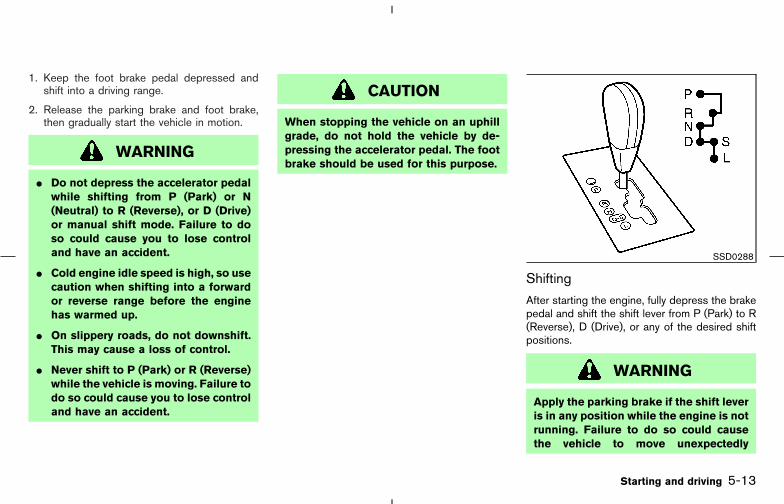
1. Keep the foot brake pedal depressed andshift into a driving range.
2. Release the parking brake and foot brake,then gradually start the vehicle in motion.
WARNING
� Do not depress the accelerator pedalwhile shifting from P (Park) or N(Neutral) to R (Reverse), or D (Drive)or manual shift mode. Failure to doso could cause you to lose controland have an accident.
� Cold engine idle speed is high, so usecaution when shifting into a forwardor reverse range before the enginehas warmed up.
� On slippery roads, do not downshift.This may cause a loss of control.
� Never shift to P (Park) or R (Reverse)while the vehicle is moving. Failure todo so could cause you to lose controland have an accident.
CAUTION
When stopping the vehicle on an uphillgrade, do not hold the vehicle by de-pressing the accelerator pedal. The footbrake should be used for this purpose.
Shifting
After starting the engine, fully depress the brakepedal and shift the shift lever from P (Park) to R(Reverse), D (Drive), or any of the desired shiftpositions.
WARNING
Apply the parking brake if the shift leveris in any position while the engine is notrunning. Failure to do so could causethe vehicle to move unexpectedly
SSD0288
Starting and driving 5-13
� 04.8.3/Z50-D/V5.0 �
or roll away and result in serious per-sonal injury or property damage.
If the key is turned to OFF or ACC for any reasonwhile the vehicle is in R (Reverse), N (Neutral), orany D (Drive) position, the key cannot be turnedto LOCK and be removed from the ignitionswitch. Additionally, the shift lever cannot bemoved to R (Reverse) from N (Neutral) or any D(Drive) position. The shift lever can be moved toR (Reverse) from any of the D (Drive) positionswithin 3 minutes after the ignition switch isturned to the ACC or OFF position. The shiftlever can be moved from R (Reverse) to P (Park)with the key in the OFF or ACC position.If the key cannot be turned to LOCK, perform thefollowing steps:
1. Apply the parking brake when the vehicle isstopped.
2. Turn the key to ON while depressing the footbrake pedal.
3. Move the shift lever to P (Park).
4. Turn the ignition switch to LOCK to removethe key.
P (Park):
Use this shift position when the vehicle is parked
or when starting the engine. Make sure thevehicle is completely stopped. The brakepedal must be depressed to move the shiftlever from N (Neutral) or any drive positionto P (Park). Apply the parking brake. Whenparking on a hill, apply the parking brake first,then move the lever to the P (Park) position.
CAUTION
Use this position only when the vehicleis completely stopped.
R (Reverse):
Use this position to back up. Always be sure thevehicle is completely stopped when selecting R(Reverse). The brake pedal must be de-pressed to move the shift lever from P(Park) to R (Reverse).
The shift lever can be moved to R (Reverse) fromany of the D (Drive) positions within 3 minutesafter the ignition switch is turned to the ACC orOFF position.
N (Neutral):
Neither forward or reverse is engaged. Theengine can be started in this position. You mayshift to N (Neutral) and restart a stalled engine
while the vehicle is moving.
D (Drive):
Use this position for all normal forward driving.
S (Second):
Use this position for the improved engine brak-ing.
L (Low):
Use this position for maximum engine braking onsteep downhill gradients/climbing steep slopesand whenever approaching sharp bends. Do notuse the L position in any other circumstances.
Shift from the D to S or L position after releasingthe accelerator pedal.
5-14 Starting and driving
� 04.8.3/Z50-D/V5.0 �

Shift lock release
If the battery charge is low or discharged, theshift lever may not be moved from the P (Park)position even with the brake pedal depressed.
To move the shift lever, depress the brake pedal,remove the cover using a suitable tool and pushthe shift lock release button. The shift lever canbe moved to N (Neutral). This allows the vehicleto be moved if the battery is discharged.
If the shift lever cannot be moved out of P (Park),have a NISSAN dealer check the CVT system assoon as possible.
Accelerator downshift— In D position —
For rapid passing or hill climbing, fully depressthe accelerator pedal to the floor. This shifts thetransmission down into lower range, dependingon the vehicle speed.
High fluid temperature protectionmode
This transmission has a high fluid temperatureprotection mode. If the fluid temperature be-comes too high (for example, when climbingsteep grades in high temperature with heavyloads, such as when towing a trailer), enginepower and, under some conditions, vehiclespeed will be decreased automatically to reducethe chance of transmission damage. Vehiclespeed can be controlled with the acceleratorpedal, but the vehicle may not accelerate aboveapproximately 40 to 50 MPH (65 to 80 km/h).
Fail-safeIf the vehicle is driven under extreme con-ditions, such as excessive wheel spinningand subsequent hard braking, the fail-safesystem may be activated. The MIL maycome on to indicate the fail-safe mode isactivated, see “Malfunction indicator lamp(MIL)” in the “2. Instrument and controls”
section. This will occur even if all electricalcircuits are functioning properly. In thiscase, turn the ignition switch to the OFFposition and wait for 10 seconds. Then turnthe switch back to the ON position. Thevehicle should return to its normal operat-ing condition. If it does not return to itsnormal operating condition, have aNISSAN dealer check the transmission andrepair if necessary.
WARNING
When the high fluid temperature protec-tion mode or fail-safe operation occurs,vehicle speed may be gradually re-duced. The reduced speed may be lowerthan other traffic, which could increasethe chance of a collision. Be especiallycareful when driving. If necessary, pullto the side of the road at a safe placeand allow the transmission to return tonormal operation, or have it repaired ifnecessary.
SSD0290
Starting and driving 5-15
� 04.8.3/Z50-D/V5.0 �
M-CVT (CVT with Manual shift mode)
Gate type shift with manual mode
The M-CVT in your vehicle is electronically con-trolled by a transmission control module to pro-duce maximum power and smooth operation.
Shown on the following pages are the recom-mended operating procedures for this transmis-sion. Follow these procedures for maximum ve-hicle performance and driving enjoyment.
Starting the vehicle
After starting the engine, fully depress the footbrake pedal before shifting the shift lever to theR (Reverse), N (Neutral), D (Drive) or manualshift mode position. Be sure the vehicle is fullystopped before attempting to shift the shift lever.
This M-CVT is designed so that the footbrake pedal MUST be depressed beforeshifting from P (Park) to any drive positionwhile the ignition switch is ON.
The shift lever cannot be moved out of P(Park) and into any of the other gear posi-tions if the ignition switch is turned to theLOCK, OFF or ACC position or if the key isremoved from the ignition switch.
1. Keep the foot brake pedal depressed andshift the shift lever into a driving gear.
2. Release the parking brake and foot brake,then gradually start the vehicle in motion.
WARNING
� Do not depress the accelerator pedalwhile shifting from P (Park) or N(Neutral) to R (Reverse), D (Drive) ormanual shift mode. Always depressthe brake pedal until shifting is com-pleted. Failure to do so could causeyou to lose control and have an acci-dent.
� Cold engine idle speed is high, so usecaution when shifting into a forwardor reverse gear before the engine haswarmed up.
� Never shift to P (Park) or R (Reverse)while the vehicle is moving. Nevershift to P (Park) or D (Drive) while thevehicle is moving rearward. Thesecould cause an accident.
� On slippery roads, do not downshift.This may cause a loss of control.
CAUTION
When stopping the vehicle on an uphillgrade, do not hold the vehicle by de-pressing the accelerator pedal. The footbrake should be used for this purpose.
5-16 Starting and driving
� 04.8.3/Z50-D/V5.0 �

Shifting
After starting the engine, fully depress the brakepedal and shift the shift lever from P (Park) to R(Reverse), N (Neutral), D (Drive), Manual shiftmode or any of the desired shift positions.
WARNING
Apply the parking brake if the shift leveris in any position while the engine is notrunning. Failure to do so could causethe vehicle to move unexpectedly
or roll away and result in serious per-sonal injury or property damage.
If the ignition switch is turned to OFF or ACC forany reason while the vehicle is in R (Reverse), N(Neutral), or any D (Drive) position, the keycannot be turned to LOCK and be removed fromthe ignition switch. Additionally, the shift levercannot be moved to R (Reverse) from N (Neu-tral) or any D (Drive) position for about 3 minutesafter the ignition switch is turned to the ACC orOFF position. The shift lever can be moved fromR (Reverse) to P (Park) with the key in the OFFor ACC position. If this occurs, perform thefollowing steps:
1. Apply the parking brake when the vehicle isstopped.
2. Turn the key to ON.
3. Depress the foot brake pedal if the vehicle isin the N (Neutral) or any D (Drive) position.
4. If necessary, move the shift lever to P (Park)or N (Neutral) to restart the vehicle (P ispreferred) or move the shift lever to P (Park)to park the vehicle.
5. Turn the ignition switch to LOCK to removethe key.
P (Park):
Use this shift position when the vehicle is parkedor when starting the engine. Make sure thevehicle is completely stopped. For maximumsafety, depress the brake pedal, then move thelever to the P (Park) position. The brake pedalmust be depressed any time the shift leveris moved to P (Park). Apply the parking brake.When parking on a hill, apply the parking brakefirst, then move the lever to the P (Park) position.
CAUTION
Use this position only when the vehicleis completely stopped.
R (Reverse):
Use this position to back up. Always be sure thevehicle is completely stopped when selecting R(Reverse). The brake pedal must be de-pressed to move the shift lever from P(Park) to R (Reverse).
The shift lever can be moved to R (Reverse) fromany of the D (Drive) positions within 3 minutesafter the ignition switch is turned to the ACC orOFF position.
SSD0289
Starting and driving 5-17
� 04.8.3/Z50-D/V5.0 �
N (Neutral):
Neither forward or reverse gear is engaged. Theengine can be started in this position. You mayshift to N (Neutral) and restart a stalled enginewhile the vehicle is moving.
D (Drive):
Use this position for all normal forward driving.
Manual shift modeWhen the shift lever is shifted from D to themanual shift gate with the vehicle stopped orwhile driving, the transmission enters the manualshift mode. Shift ranges can be selected manu-ally.
In the manual shift mode, the shift range isdisplayed on the position indicator in the meter.
Shift ranges up or down one by one as follows:
M1→← M2
→← M3
→← M4
→← M5
→← M6
M6 (Sixth):
Use this position for all normal forward driving.
M5 (Fifth):
For driving up or down long slopes where enginebraking would be advantageous.
M4 (Fourth), M3 (Third) and M2 (Second):
Use for hill climbing or engine braking on down-hill grades.
M1 (First):
Use this position when climbing steep hillsslowly or driving slowly through deep snow,sand or mud, or for maximum engine braking onsteep downhill grades.
� Remember not to drive at high speeds forextended periods of time in lower than M6range. This reduces fuel economy.
� When shifting up, move the shift lever to the+ (up) side. (Shifts to higher range.)
� When shifting down, move the shift lever tothe − (down) side. (Shifts to lower range.)
� Moving the shift lever to the same side twicewill shift the ranges in succession. However,if this motion is rapidly done, the secondshifting may not be completed properly.
� In the manual shift mode, the transmis-sion automatically shifts down to M1(First) before the vehicle comes to astop. When accelerating again, it is nec-essary to shift up to the desired range.
� When canceling the manual shift mode, re-turn the shift lever to the D position. The
transmission returns to the normal drivingmode.
� In the manual shift mode, the transmis-sion may not shift to the selected gear.This helps maintain driving performanceand reduces the chance of vehicle dam-age or loss of control.
� When the CVT fluid temperature is extremelylow, the manual shift mode may not work andautomatically shift as a drive mode. This is nota malfunction. In this case, return the shiftlever to D range and drive for a while and thenshift to the manual shift mode.
� When the CVT fluid temperature is high, theshift range may upshift in lower rpm thanusual. This is not a malfunction.
5-18 Starting and driving
� 04.8.3/Z50-D/V5.0 �

Shift lock release
If the battery is discharged, the shift lever maynot be moved from the P (Park) position evenwith the brake pedal depressed.
To move the shift lever, push the shift lockrelease button while depressing the foot brakeand applying the parking brake. The selectorlever can be moved to N (Neutral). This allowsthe vehicle to be moved if the battery is dis-charged, after releasing the parking brake.
If the battery is discharged in N (Neutral), D(Drive) or Manual shift mode, the select levermay not be moved to the P (Park) position.
If it is necessary to park the vehicle, push theshift lock release button, then move the shiftlever to the P (Park).
To push the shift lock release button, follow theprocedure as illustrated.
If the lever cannot be moved out of P (Park), havea NISSAN dealer check the CVT system as soonas possible.
WARNING
� If the shift lever cannot be movedfrom the P (Park) position while theengine is running and the brakepedal is depressed, the stop lightsmay not work. Malfunctioning stoplights could cause an accident injur-ing yourself and others.
� Do not park the vehicle without shift-ing to the P (Park) position.
Accelerator downshift— In D position —For passing or hill climbing, fully depress theaccelerator pedal to the floor. This shifts thetransmission down into the lower gear, depend-
ing on the vehicle speed.
High fluid temperature protectionmode
This transmission has a high fluid temperatureprotection mode. If the fluid temperature be-comes too high (for example, when climbingsteep grades in high temperature with heavyloads, such as when towing a trailer), enginepower and, under some conditions, vehiclespeed will be decreased automatically to reducethe chance of transmission damage. Vehiclespeed can be controlled with the acceleratorpedal, but the vehicle may not accelerate aboveapproximately 40 to 50 MPH (65 to 80 km/h).
Fail-safeIf the vehicle is driven under extreme con-ditions, such as excessive wheel spinningand subsequent hard braking, the fail-safesystem may be activated. The MIL maycome on to indicate the fail-safe mode isactivated, see “Malfunction indicator lamp(MIL)” in the “2. Instrument and controls”section. This will occur even if all electricalcircuits are functioning properly. In thiscase, turn the ignition switch to the OFFposition and wait for 10 seconds. Then turnthe switch back to the ON position. Thevehicle should return to its normal operat-
SSD0352
Starting and driving 5-19
� 04.8.3/Z50-D/V5.0 �
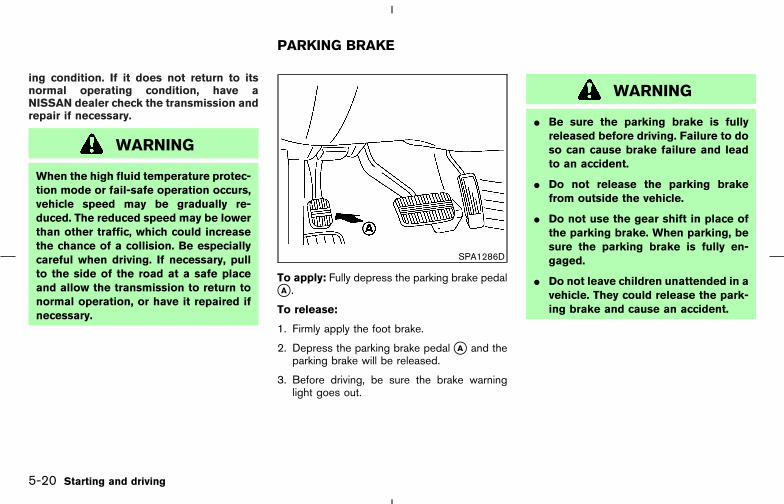
ing condition. If it does not return to itsnormal operating condition, have aNISSAN dealer check the transmission andrepair if necessary.
WARNING
When the high fluid temperature protec-tion mode or fail-safe operation occurs,vehicle speed may be gradually re-duced. The reduced speed may be lowerthan other traffic, which could increasethe chance of a collision. Be especiallycareful when driving. If necessary, pullto the side of the road at a safe placeand allow the transmission to return tonormal operation, or have it repaired ifnecessary.
To apply: Fully depress the parking brake pedal�A .
To release:
1. Firmly apply the foot brake.
2. Depress the parking brake pedal �A and theparking brake will be released.
3. Before driving, be sure the brake warninglight goes out.
WARNING
� Be sure the parking brake is fullyreleased before driving. Failure to doso can cause brake failure and leadto an accident.
� Do not release the parking brakefrom outside the vehicle.
� Do not use the gear shift in place ofthe parking brake. When parking, besure the parking brake is fully en-gaged.
� Do not leave children unattended in avehicle. They could release the park-ing brake and cause an accident.
SPA1286D
PARKING BRAKE
5-20 Starting and driving
� 04.8.3/Z50-D/V5.0 �

WARNING
Do not use the cruise control when driv-ing under the following conditions:
� When it is not possible to keep thevehicle at a set speed.
� In heavy traffic or in traffic that variesin speed.
� On winding or hilly roads.
� On slippery roads (rain, snow, ice,etc.).
� In very windy areas.
Doing so could cause a loss of vehiclecontrol and result in an accident.
PRECAUTIONS ON CRUISECONTROL
� If the cruise control system malfunctions, itcancels automatically. The SET indicator lighton the meter panel then blinks to warn thedriver.
� If the SET indicator light blinks, turn thecruise control main switch off and have thesystem checked by a NISSAN dealer.
� The SET indicator light may blink when thecruise control main switch is turned on whilepushing the RESUME/ACCELERATOR,SET/COAST, or CANCEL switch. To prop-erly set the cruise control system, perform thepreceding steps in the order indicated.
1. RESUME/ACCELERATOR switch
2. SET/COAST switch
3. MAIN (ON/OFF) switch
4. CANCEL switch
CRUISE CONTROL OPERATIONS
The cruise control allows driving at a speedbetween 25 to 89 MPH (40 to 144 km/h)without keeping your foot on the acceleratorpedal.
To turn on the cruise control, push the mainswitch on. The CRUISE indicator light on themeter panel will come on.
SSD0297
CRUISE CONTROL
Starting and driving 5-21
� 04.8.3/Z50-D/V5.0 �

To set cruising speed, accelerate your vehicleto the desired speed, push the SET/COASTswitch and release it. (The SET indicator lightwill come on.) Take your foot off the acceleratorpedal. Your vehicle will maintain the set speed.
� To pass another vehicle, depress the ac-celerator pedal. When you release the pedal,the vehicle will return to the previously setspeed.
� The vehicle may not maintain the set speedon winding or hilly roads. If this happens,drive without the cruise control.
To cancel the preset speed, follow any ofthese methods:
a) Push the CANCEL switch; The SET indicatorlight will go out.
b) Tap the brake pedal; The SET indicator lightwill go out.
c) Turn the main switch off. Both the CRUISEindicator and SET indicator lights will go out.
� If you depress the brake pedal while pushingthe RESUME/ACCELERATOR set switchand reset at the cruising speed, turn the mainswitch off once and then turn it on again.
� The cruise control will automatically be can-celled if the vehicle slows down below ap-proximately 8 MPH (13 km/h).
� Move the shift lever to N (Neutral) position.The SET indicator light will go out.
To reset at a faster cruising speed, use oneof the following three methods:
a) Depress the accelerator pedal. When thevehicle attains the desired speed, push andrelease the SET/COAST switch.
b) Push and hold the RESUME/ACCELERATOR set switch. When the ve-hicle attains the speed you desire, release theswitch.
c) Push, then quickly release the RESUME/ACCELERATOR set switch. Each time youdo this, the set speed will increase by about1 MPH (1.6 km/h).
To reset at a slower cruising speed, use oneof the following three methods:
a) Lightly tap the brake pedal. When the vehicleattains the desired speed, push the SET/COAST switch and release it.
b) Push and hold the SET/COAST switch. Re-lease the switch when the vehicle slowsdown to the desired speed.
c) Push, then quickly release the SET/COASTswitch. Each time you do this, the set speedwill decrease by about 1 MPH (1.6 km/h).
To resume the preset speed, push and re-lease the RESUME/ACCELERATOR set switch.The vehicle will resume the last set cruisingspeed when the vehicle speed is over 25 MPH(40 km/h).
5-22 Starting and driving
� 04.8.3/Z50-D/V5.0 �

CAUTION
During the first 1,200 miles (2,000 km),follow these recommendations to ob-tain maximum engine performance andensure the future reliability andeconomy of your new vehicle. Failure tofollow these recommendations may re-sult in shortened engine life and re-duced engine performance.
� Avoid driving for long periods at constantspeed, either fast or slow. Do not run theengine over 4,000 rpm.
� Do not accelerate at full throttle in any gear.
� Avoid quick starts.
� Avoid hard braking as much as possible.
� Do not tow a trailer for the first 500 miles(800 km).
� Accelerate slowly and smoothly. Maintaincruising speeds with a constant acceleratorposition.
� Drive at moderate speeds on the highway.Driving at high speed will lower fuel economy.
� Avoid unnecessary stopping and braking.Maintain a safe distance behind other ve-hicles.
� Use a proper gear range which suits roadconditions. On level roads, shift into high gearas soon as possible.
� Avoid unnecessary engine idling.
� Keep your engine tuned up.
� Follow the recommended periodic mainte-nance schedule.
� Keep the tires inflated at the correct pres-sure. Low pressure will increase tire wear andwaste fuel.
� Keep the front wheels in correct alignment.Improper alignment will cause not only tirewear but also lower fuel economy.
� Air conditioner operation lowers fueleconomy. Use the air conditioner only whennecessary.
� When cruising at highway speeds, it is moreeconomical to use the air conditioner and
leave the windows closed to reduce drag.
BREAK-IN SCHEDULE INCREASING FUEL ECONOMY
Starting and driving 5-23
� 04.8.3/Z50-D/V5.0 �

WARNING
A vehicle equipped with AWD (All-Wheel Drive) should never be testedusing a two wheel dynamometer, similarto the dynamometers used by somestates for emissions testing, or similarequipment. Make sure you inform thetest facility personnel that your vehicleis an AWD equipped vehicle before it isplaced on a dynamometer. Failure to doso may result in transmission damage
or unexpected vehicle movement whichcould result in serious vehicle damageor personal injury.
AWD LOCK SWITCH OPERATIONSThe AWD LOCK switch located in front of theshift lever is used to select AUTO/LOCK de-pending on the driving conditions.
Each time you push the lower part of the switch,the AWD mode will switch: AUTO → LOCK →AUTO.
The AWD system electronically controls thecoupling.
Push the lower part of the AWD LOCK switch�A to select the AUTO or LOCK mode depend-ing on the driving conditions.
LOCK modePush the lower part of the switch �A when thevehicle is stopped or driving under approximately10 km/h (6 MPH).The AWD LOCK indicator light will come on.
AUTO modePush the lower part of the switch �A . The AWDLOCK indicator light will go off.
SSD0418
USING ALL WHEEL DRIVE (AWD)(if so equipped)
5-24 Starting and driving
� 04.8.3/Z50-D/V5.0 �
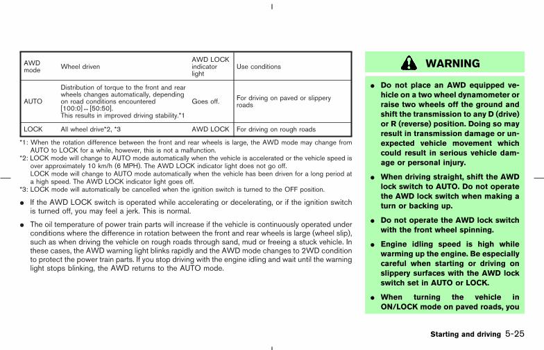
AWDmode Wheel driven
AWD LOCKindicatorlight
Use conditions
AUTO
Distribution of torque to the front and rearwheels changes automatically, dependingon road conditions encountered[100:0]↔[50:50].This results in improved driving stability.*1
Goes off. For driving on paved or slipperyroads
LOCK All wheel drive*2, *3 AWD LOCK For driving on rough roads
*1: When the rotation difference between the front and rear wheels is large, the AWD mode may change fromAUTO to LOCK for a while, however, this is not a malfunction.
*2: LOCK mode will change to AUTO mode automatically when the vehicle is accelerated or the vehicle speed isover approximately 10 km/h (6 MPH). The AWD LOCK indicator light does not go off.LOCK mode will change to AUTO mode automatically when the vehicle has been driven for a long period ata high speed. The AWD LOCK indicator light goes off.
*3: LOCK mode will automatically be cancelled when the ignition switch is turned to the OFF position.
� If the AWD LOCK switch is operated while accelerating or decelerating, or if the ignition switchis turned off, you may feel a jerk. This is normal.
� The oil temperature of power train parts will increase if the vehicle is continuously operated underconditions where the difference in rotation between the front and rear wheels is large (wheel slip),such as when driving the vehicle on rough roads through sand, mud or freeing a stuck vehicle. Inthese cases, the AWD warning light blinks rapidly and the AWD mode changes to 2WD conditionto protect the power train parts. If you stop driving with the engine idling and wait until the warninglight stops blinking, the AWD returns to the AUTO mode.
WARNING
� Do not place an AWD equipped ve-hicle on a two wheel dynamometer orraise two wheels off the ground andshift the transmission to any D (drive)or R (reverse) position. Doing so mayresult in transmission damage or un-expected vehicle movement whichcould result in serious vehicle dam-age or personal injury.
� When driving straight, shift the AWDlock switch to AUTO. Do not operatethe AWD lock switch when making aturn or backing up.
� Do not operate the AWD lock switchwith the front wheel spinning.
� Engine idling speed is high whilewarming up the engine. Be especiallycareful when starting or driving onslippery surfaces with the AWD lockswitch set in AUTO or LOCK.
� When turning the vehicle inON/LOCK mode on paved roads, you
Starting and driving 5-25
� 04.8.3/Z50-D/V5.0 �
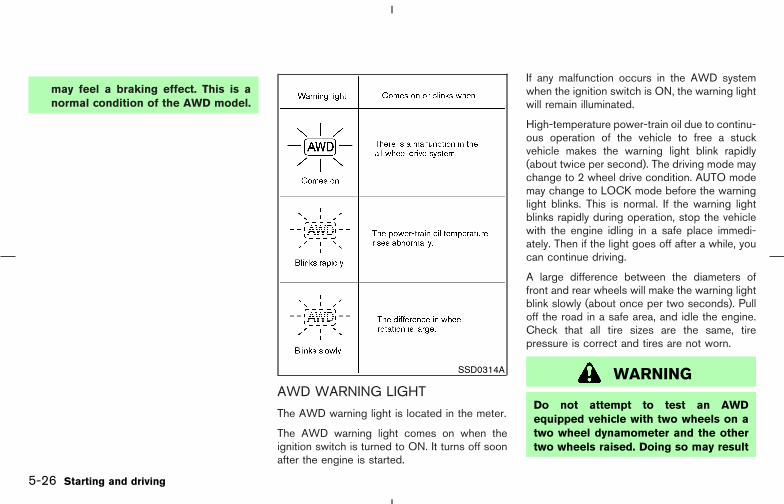
may feel a braking effect. This is anormal condition of the AWD model.
AWD WARNING LIGHT
The AWD warning light is located in the meter.
The AWD warning light comes on when theignition switch is turned to ON. It turns off soonafter the engine is started.
If any malfunction occurs in the AWD systemwhen the ignition switch is ON, the warning lightwill remain illuminated.
High-temperature power-train oil due to continu-ous operation of the vehicle to free a stuckvehicle makes the warning light blink rapidly(about twice per second). The driving mode maychange to 2 wheel drive condition. AUTO modemay change to LOCK mode before the warninglight blinks. This is normal. If the warning lightblinks rapidly during operation, stop the vehiclewith the engine idling in a safe place immedi-ately. Then if the light goes off after a while, youcan continue driving.
A large difference between the diameters offront and rear wheels will make the warning lightblink slowly (about once per two seconds). Pulloff the road in a safe area, and idle the engine.Check that all tire sizes are the same, tirepressure is correct and tires are not worn.
WARNING
Do not attempt to test an AWDequipped vehicle with two wheels on atwo wheel dynamometer and the othertwo wheels raised. Doing so may result
SSD0314A
5-26 Starting and driving
� 04.8.3/Z50-D/V5.0 �

in transmission damage or unexpectedvehicle movement which could result inserious vehicle damage or personal in-jury.
CAUTION
� If the warning light comes on whiledriving, AUTO or LOCK mode will bechanged to 2 wheel drive condition.Reduce the vehicle speed and haveyour vehicle checked by a NISSANdealer as soon as possible.
� When the warning light comes on,the 2 wheel condition may be en-gaged even if the driving mode is inAUTO or LOCK. Be especially carefulwhen driving.
� Never drive on dry hard surface roadsin the LOCK mode, as this will over-load the power-train and may cause aserious malfunction.
� If the warning light is still on after theabove operation, have your vehicle
checked by a NISSAN dealer as soonas possible.
� The power-train may be damaged ifyou continue driving with the warninglight blinking rapidly.
Starting and driving 5-27
� 04.8.3/Z50-D/V5.0 �

WARNING
� Do not stop or park the vehicle overflammable materials such as drygrass, waste paper or rags. They mayignite and cause a fire.
� Never leave the engine running whilethe vehicle is unattended.
� Do not leave children unattended in-side the vehicle.
1. Firmly apply the parking brake.
2. Move the shift lever to the P (Park) position.
WARNING
� Safe parking procedures require thatboth the parking brake be set and thetransmission placed into P (Park).Failure to do so could cause the ve-hicle to move unexpectedly or rollaway and result in an accident.
� Make sure the shift lever has beenpushed as far forward as it can goand cannot be moved without de-pressing the button at the end of thelever.
3. To help prevent the vehicle from rolling intothe street when parked on a sloping driveway, it is a good practice to turn the wheelsas illustrated.
� HEADED DOWNHILL WITH CURB: �1Turn the wheels into the curb and move thevehicle forward until the curb side wheelgently touches the curb.
SD1006MA
PARKING/PARKING ON HILLS
5-28 Starting and driving
� 04.8.3/Z50-D/V5.0 �
� HEADED UPHILL WITH CURB: �2Turn the wheels away from the curb andmove the vehicle back until the curb sidewheel gently touches the curb.
� HEADED UPHILL OR DOWNHILL, NOCURB: �3Turn the wheels toward the side of the roadso the vehicle will move away from the centerof the road if it moves.
4. Turn the ignition switch to the LOCK positionand remove the key.
The power assisted steering is designed to usea hydraulic pump, driven by the engine, to assiststeering.
If the engine stops or drive belt breaks, you willstill have control of the vehicle. However, muchgreater steering effort is needed, especially insharp turns or at low speeds.
WARNING
If the engine is not running or is turnedoff while driving, the power assist forthe steering will not work. Steering willbe much harder to operate.
BRAKING PRECAUTIONS
The brake system has two separate hydrauliccircuits. If one circuit malfunctions, you will stillhave braking at two wheels.
Vacuum assisted brake
The brake booster aids braking by using enginevacuum. If the engine stops, you can stop thevehicle by depressing the brake pedal. However,greater foot pressure on the brake pedal will berequired to stop the vehicle and the stoppingdistance will be longer.
Wet brakes
When the vehicle is washed or driven throughwater, the brakes may get wet. As a result, yourbraking distance will be longer and the vehiclemay pull to one side during braking.
To dry brakes, drive the vehicle at a safe speedwhile lightly tapping the brake pedal to heat-upthe brakes. Do this until the brakes return tonormal. Avoid driving the vehicle at high speedsuntil the brakes function correctly.
Using the brakes
Avoid resting your foot on the brake pedal whiledriving. This will cause overheating of the brakes,increases wear on the brake linings and pads,and reduces gas mileage.
POWER STEERING BRAKE SYSTEM
Starting and driving 5-29
� 04.8.3/Z50-D/V5.0 �
To help save the brakes and to prevent thebrakes from overheating, reduce speed anddownshift to a lower gear before going down aslope or long grade. Overheated brakes mayreduce braking performance and could result inloss of vehicle control.
WARNING
� While driving on a slippery surface,be careful when braking, accelerat-ing or downshifting. Abrupt brakingor accelerating could cause thewheels to skid and result in an acci-dent.
� If the engine is not running or isturned off while driving, the powerassist for the brakes will not work.Braking will be harder.
ANTI-LOCK BRAKE SYSTEM (ABS)
The anti-lock brake system controls the brakesat each wheel so the wheels will not lock whenbraking abruptly or when braking on slipperysurfaces. The system detects the rotation speedat each wheel and varies the brake fluid pressureto prevent each wheel from locking and sliding.
By preventing wheel lockup, the system helpsthe driver maintain steering control and helps tominimize swerving and spinning on slippery sur-faces.
Using the system
Depress the brake pedal and hold it down.
WARNING
Do not pump the brake pedal. Doing somay result in increased stopping dis-tances.
Normal operation
The anti-lock brake system will not operate atspeeds below 3 to 6 MPH (5 to 10 km/h) tocompletely stop the vehicle. (The speeds willvary according to road conditions.) When theanti-lock system senses that one or more wheelsare close to locking up, the actuator (under thehood) rapidly applies and releases hydraulicpressure (like pumping the brakes very quickly).While the actuator is working, you may feel apulsation in the brake pedal and hear a noise orvibration from the actuator under the hood. Thisis normal and indicates that the anti-lock systemis working properly. However, the ABS operation
may indicate that road conditions are hazardousand extra care is required while driving.
Self-test feature
The anti-lock brake system consists of electronicsensors, electric pumps, and hydraulic solenoidscontrolled by a computer. The computer has abuilt-in diagnostic feature that tests the systemeach time you start the engine and move thevehicle at a low speed in forward or reverse.When the self-test occurs, you may hear a clunknoise and/or feel a pulsation in the brake pedal.This is normal and is not an indication of anymalfunction. If the computer senses any mal-function, it switches the anti-lock brake systemOFF and turns on the ABS warning light in themeter. The brake system will then behave nor-mally, but without anti-lock assistance.
If the light comes on during the self check, orwhile you are driving, you should take yourvehicle to a NISSAN dealer for repair at yourearliest convenience.
WARNING
The anti-lock brake system is a sophis-ticated device, but it cannot prevent ac-
5-30 Starting and driving
� 04.8.3/Z50-D/V5.0 �
cidents resulting from careless or dan-gerous driving techniques. It can helpmaintain vehicle control during brakingon slippery surfaces, but remember thatthe stopping distance on slippery sur-faces will be longer than on normalsurfaces even with the anti-lock brakesystem. Stopping distances may also belonger on rough, gravel or snow coveredroads, or if you are using tire chains.Always maintain a safe distance fromthe vehicle in front of you. Ultimately,the responsibility for safety of self andothers rests in the hands of the driver.
Tire type and condition of tires may alsoaffect braking effectiveness.
� When replacing tires, install thespecified size of tires on all fourwheels.
� When installing a spare tire, makesure it is the proper size and type asspecified on the tire placard. See“Vehicle identification” in the “9.Technical and consumer informa-tion” section for tire placard location.
When accelerating or driving on a slippery sur-faces, the tires may spin or slide. With theVehicle Dynamic Control (VDC) system, sensorsdetect these movements and control the brakingand engine output to help improve vehicle sta-bility.
� When the VDC system is operating, the“SLIP” indicator in the instrument panelblinks.
� When only the Traction Control System(TCS) portion of the VDC system is operat-ing, the “SLIP” indicator in the instrumentpanel blinks.
� If the “SLIP” indicator blinks, the road condi-tions are slippery. Be sure to adjust yourspeed and driving to these conditions. Besure to drive carefully. See “Slip indicatorlight”, and “Vehicle Dynamic Control (VDC)OFF indicator light” in the “2. Instruments andcontrols” section.
� Indicator lightIf a malfunction occurs in the system, the“SLIP” and “VDC OFF” indicator lights illumi-nate in the instrument panel. As long as theseindicators are illuminated, the VDC systemfunction is canceled.
The VDC system uses an Active Brake LimitedSlip (ABLS) system to improve vehicle traction.
The ABLS system works when one of the drivingwheels is spinning on a slippery surface. TheABLS system brakes the spinning wheel, whichdistributes the driving power to the other drivingwheel. If the vehicle is operated with the VDCsystem turned off, all VDC system functions andTCS functions will be turned off. The ABLSsystem and ABS will still operate with the VDCsystem off. When the ABLS system is activated,the “SLIP” indicator light will blink and you mayhear a clunk noise and/or feel a pulsation in thebrake pedal. This is normal and is not an indica-tion of a malfunction.
While the VDC system is operating, you may feela pulsation in the brake pedal and hear a noise orfeel a vibration from under the hood. This isnormal and indicates that the VDC system isworking properly.
The VDC system computer has a built-in diag-nostic feature that tests the system each timeyou start the engine and move the vehicle for-ward or backward. When the self-test occurs,you may hear a clunk noise and/or feel a pulsa-tion in the brake pedal. This is normal and is notan indication of a malfunction.
VEHICLE DYNAMIC CONTROL(VDC) SYSTEM (if so equipped)
Starting and driving 5-31
� 04.8.3/Z50-D/V5.0 �

WARNING
� The VDC system is designed to helpimprove driving stability but does notprevent accidents due to abruptsteering operation at high speeds ordue to careless or dangerous drivingtechniques. Reduce vehicle speedand be especially careful when driv-ing and cornering on slippery sur-faces and always drive carefully.
� If engine related parts such as a muf-fler are not standard equipment orare extremely deteriorated, the “VDCOFF” indicator or “SLIP” indicator orboth indicator lights may illuminate.
� Do not modify the vehicle’s suspen-sion. If suspension parts such asshock absorbers, struts, springs, sta-bilizer bars and bushings are notNISSAN-approved or are extremelydeteriorated the VDC system may notoperate properly. This could ad-versely affect vehicle handling per-formance, and the “VDC OFF” indica-
tor or “SLIP” indicator or both indica-tor lights may illuminate.
� If brake related parts such as brakepads, rotors and calipers are notstandard equipment or are extremelydeteriorated, the “VDC OFF” indica-tor or “SLIP” indicator or both indica-tor lights may illuminate.
� When driving on extremely inclinedsurfaces such as higher banked cor-ners, the VDC system may not oper-ate properly and the “VDC OFF” indi-cator or “SLIP” indicator or bothindicator lights may illuminate. Donot drive on these types of roads.
� When driving on an unstable surfacesuch as a turntable, ferry, elevator orramp, the “VDC OFF” indicator or“SLIP” indicator or both indicatorlights may illuminate. This is not amalfunction. Restart the engine afterdriving onto a stable surface.
� If wheels or tires other than thoserecommended are used, the VDC sys-
temmay not operate properly and the“VDC OFF” indicator or “SLIP” indi-cator or both indicator lights mayilluminate.
� The VDC system is not a substitutefor winter tires or tire chains on asnow-covered road.
5-32 Starting and driving
� 04.8.3/Z50-D/V5.0 �
FREEING A FROZEN DOOR LOCKTo prevent a door lock from freezing, applyde-icer or glycerin to it through the key hole. Ifthe lock becomes frozen, heat the key beforeinserting it into the key hole.
ANTIFREEZEIn the winter when it is anticipated that thetemperature will drop below 32°F (0°C), checkantifreeze to assure proper winter protection. Foradditional information, see “Engine cooling sys-tem” in the “8. Maintenance and do-it-yourself”section.
BATTERYIf the battery is not fully charged during extremelycold weather conditions, the battery fluid mayfreeze and damage the battery. To maintainmaximum efficiency, the battery should bechecked regularly. For additional information,see “Battery” in the “8. Maintenance and do-it-yourself” section.
DRAINING OF COOLANT WATERIf the vehicle is to be left outside without anti-freeze, drain the cooling system by opening thedrain plug located under the radiator. Refillbefore operating the vehicle. See “Engine cool-ing system” in the “8. Maintenance and do-it-yourself” section for changing engine coolant.
TIRE EQUIPMENT
1. SUMMER tires are of a tread design toprovide superior performance on dry pave-ment. However, the performance of thesetires will be substantially reduced in snowyand icy conditions. If you operate your vehicleon snowy or icy roads, NISSAN recommendsthe use of MUD & SNOW or ALL SEASONtires on all four wheels. Please consult aNISSAN dealer for the tire type, size, speedrating and availability information.
2. For additional traction on icy roads, studdedtires may be used. However, some provincesand states prohibit their use. Check local,state and provincial laws before installingstudded tires.
Skid and traction capabilities of studdedsnow tires, on wet or dry surfaces, may bepoorer than that of non-studded snowtires.
3. Tire chains may be used if desired. Make surethey are of proper size for the tires on yourvehicle and are installed according to thechain manufacturer’s suggestions. Use of tirechains may be prohibited according to loca-tion. Check the local laws before installingtire chains. When installing tire chains, makesure they are of proper size for the tires onyour vehicle and are installed according to
the chain manufacturer’s suggestions. Useonly SAE Class S chains. Class “S” chainsare used on vehicles with restricted tire tovehicle clearance. Vehicles that can useClass “S” chains are designed to meet theSAE standard minimum clearances betweenthe tire and the closest vehicle suspension orbody component required to accommodatethe use of a winter traction device (tire chainsor cables). The minimum clearances are de-termined using the factory equipped tire size.Other types may damage your vehicle. Usechain tensioners when recommended by thetire chain manufacturer to ensure a tight fit.Loose end links of the tire chain must besecured or removed to prevent the possibilityof whipping action damage to the fenders orunderbody. If possible, avoid fully loadingyour vehicle when using tire chains. In addi-tion, drive at a reduced speed. Otherwise,your vehicle may be damaged and/or vehiclehandling and performance may be adverselyaffected.
� Never install tire chains on TEMPO-RARY USE ONLY spare tires.
� Do not use tire chains on dry roads.
Tire chains must be installed only on thefront wheels and not on the rear wheels.
Do not drive with tire chains on paved roads
COLD WEATHER DRIVING
Starting and driving 5-33
� 04.8.3/Z50-D/V5.0 �

which are clear of snow. Driving with chains insuch conditions can cause damage to the vari-ous mechanisms of the vehicle due to someoverstress.
4. For all wheel drive:If you install snow tires, they must also be thesame size, brand, construction and treadpattern on all four wheels.
SPECIAL WINTER EQUIPMENT
It is recommended that the following items becarried in the vehicle during winter:
� a scraper and stiff-bristled brush to removeice and snow from the windows and wiperblades.
� a sturdy, flat board to be placed under thejack to give it firm support.
� a shovel to dig the vehicle out of snow-drifts.
� extra window washer fluid to refill the reser-voir tank.
DRIVING ON SNOW OR ICE
WARNING
� Wet ice (32°F, 0°C and freezing rain),
very cold snow or ice can be slick andvery hard to drive on. The vehicle willhave much less traction or “grip” un-der these conditions. Try to avoiddriving on wet ice until the road issalted or sanded.
� Whatever the condition, drive withcaution. Accelerate and slow downwith care. If accelerating or down-shifting too fast, the drive wheels willlose even more traction.
� Allow more stopping distance underthese conditions. Braking should bestarted sooner than on dry pavement.
� Allow greater following distances onslippery roads.
� Watch for slippery spots (glare ice).These may appear on an otherwiseclear road in shaded areas. If a patchof ice is seen ahead, brake beforereaching it. Try not to brake while onthe ice, and avoid any sudden steer-ing maneuvers.
� Do not use cruise control on slipperyroads.
� Snow can trap dangerous exhaustgases under your vehicle. Keep snowclear of the exhaust pipe and fromaround your vehicle.
ENGINE BLOCK HEATER (if soequipped)An engine block heater to assist extreme coldtemperature starting is available through aNISSAN dealer.
WARNING
Do not use your heater with an un-grounded electrical system or two-pronged (cheater) adapters. You can beinjured by an electrical shock if you usean ungrounded connection.
5-34 Starting and driving
� 04.8.3/Z50-D/V5.0 �
6 In case of emergency
Flat tire...................................................................................... 6-2Low tire pressure warning system(if so equipped) ................................................................ 6-2Changing a flat tire .......................................................... 6-2
Jump starting........................................................................... 6-8
Push starting......................................................................... 6-10If your vehicle overheats .................................................... 6-11Towing your vehicle ............................................................ 6-12
Towing recommended by NISSAN........................... 6-13Vehicle recovery (Freeing a stuck vehicle) ............. 6-14
� 04.8.3/Z50-D/V5.0 �

LOW TIRE PRESSURE WARNINGSYSTEM (if so equipped)
This vehicle is equipped with the low tire pres-sure warning system. It monitors tire pressure ofall tires except the spare. When the tire pressurewarning light is lit, one or more of your tires issignificantly underinflated. If equipped, the sys-tem also displays pressure of all tires (except thespare tire) on the display screen by sending asignal from a sensor that is installed in eachwheel. If the vehicle is being driven with low tirepressure (lower than 27 psi, 190 kPa), the lowtire pressure warning system will activate andwarn you of it by the low tire pressure warninglight. This system will activate only when thevehicle is driven at speeds above 20 MPH (32km/h). For more details, please refer to“Warning/indicator lights and audible remind-ers” in the “2. Instruments and controls” section,“Tire pressure information” in the “4. Displayscreen, heater, air conditioner and audio sys-tems” section and “Low tire pressure warningsystem” in the “5. Starting and driving” section.
WARNING
� If the light comes on while driving,avoid sudden steering maneuvers or
abrupt braking, reduce vehicle speed,pull off the road to a safe locationand stop the vehicle as soon as pos-sible. Serious vehicle damage couldoccur and may lead to an accidentand could result in serious personalinjury. Check the tire pressure for allfour tires. Adjust the tire pressure tothe recommended COLD tire pres-sure shown on the Tire and LoadingInformation label to turn the low tirepressure warning light OFF. If thelight still comes on while driving afteradjusting the tire pressure, a tire maybe flat. If you have a flat tire, replaceit with a spare tire as soon as pos-sible.
� When a spare tire is mounted or awheel is replaced, the pressure ofthat tire will not be indicated or moni-tored by the low tire pressure warn-ing system. Contact a NISSAN dealeras soon as possible for tire replace-ment and/or system resetting.
� Do not inject any tire liquid or aerosoltire sealant into the tires, as this maycause a malfunction of the tire pres-sure sensors.
CHANGING A FLAT TIREIf you have a flat tire, follow the instructionsbelow.
Stopping the vehicle1. Safely move the vehicle off the road away
from traffic.
2. Turn on the hazard warning flashers.
3. Park on a level surface and apply the parkingbrake. Shift the shift lever into P (Park) posi-tion.
4. Turn off the engine.
5. Raise the hood to warn other traffic, and tosignal professional road assistance person-nel that you need assistance.
6. Have all passengers get out of the vehicleand stand in a safe place, away from trafficand clear of the vehicle.
FLAT TIRE
6-2 In case of emergency
� 04.8.3/Z50-D/V5.0 �
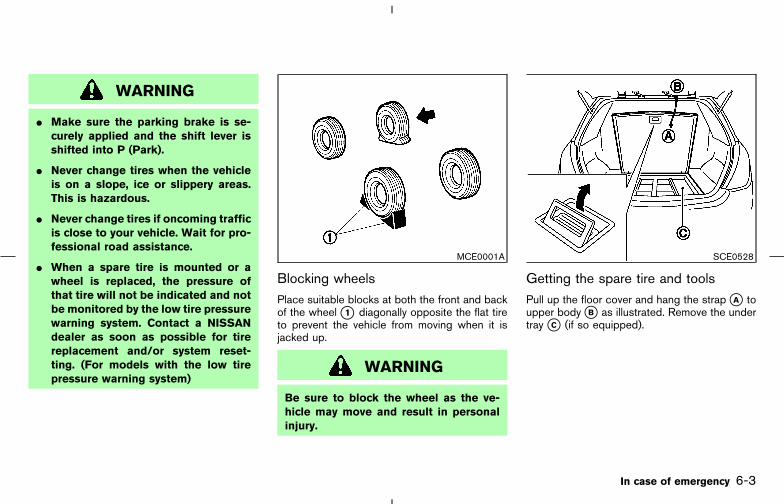
WARNING
� Make sure the parking brake is se-curely applied and the shift lever isshifted into P (Park).
� Never change tires when the vehicleis on a slope, ice or slippery areas.This is hazardous.
� Never change tires if oncoming trafficis close to your vehicle. Wait for pro-fessional road assistance.
� When a spare tire is mounted or awheel is replaced, the pressure ofthat tire will not be indicated and notbe monitored by the low tire pressurewarning system. Contact a NISSANdealer as soon as possible for tirereplacement and/or system reset-ting. (For models with the low tirepressure warning system)
Blocking wheelsPlace suitable blocks at both the front and backof the wheel �1 diagonally opposite the flat tireto prevent the vehicle from moving when it isjacked up.
WARNING
Be sure to block the wheel as the ve-hicle may move and result in personalinjury.
Getting the spare tire and toolsPull up the floor cover and hang the strap �A toupper body �B as illustrated. Remove the undertray �C (if so equipped).
MCE0001A SCE0528
In case of emergency 6-3
� 04.8.3/Z50-D/V5.0 �
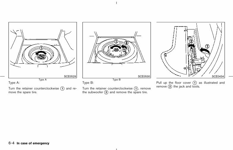
Type A:
Turn the retainer counterclockwise �1 and re-move the spare tire.
Type B:
Turn the retainer counterclockwise �1 , removethe subwoofer �2 and remove the spare tire.
Pull up the floor cover �1 as illustrated andremove �2 the jack and tools.
SCE0529Type A
SCE0530Type B
SCE0434
6-4 In case of emergency
� 04.8.3/Z50-D/V5.0 �
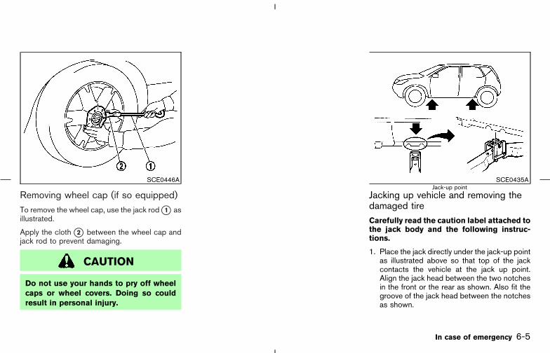
Removing wheel cap (if so equipped)To remove the wheel cap, use the jack rod �1 asillustrated.
Apply the cloth �2 between the wheel cap andjack rod to prevent damaging.
CAUTION
Do not use your hands to pry off wheelcaps or wheel covers. Doing so couldresult in personal injury.
Jacking up vehicle and removing thedamaged tireCarefully read the caution label attached tothe jack body and the following instruc-tions.
1. Place the jack directly under the jack-up pointas illustrated above so that top of the jackcontacts the vehicle at the jack up point.Align the jack head between the two notchesin the front or the rear as shown. Also fit thegroove of the jack head between the notchesas shown.
SCE0446A SCE0435AJack-up point
In case of emergency 6-5
� 04.8.3/Z50-D/V5.0 �

The jack should be used on level firmground.
2. Loosen each wheel nut one or two turns byturning counterclockwise with the wheel nutwrench. Do not remove the wheel nutsuntil the tire is off the ground.
3. Carefully raise the vehicle until the tire clearsthe ground. To lift the vehicle, securely holdthe jack lever and rod with both hands asshown above. Remove the wheel nuts, andthen remove the tire.
WARNING
� Never get under the vehicle while it issupported only by the jack. If it isnecessary to work under the vehicle,support it with safety stands.
� Use only the jack provided with yourvehicle to lift the vehicle. Do not usethe jack provided with your vehicleon other vehicles.The jack is designed for lifting only
your vehicle during a tire change.
� Never use any other part of the ve-hicle for jack support.
� Never jack up the vehicle more thannecessary.
� Never use blocks on or under thejack.
� Do not start or run the engine whilevehicle is on the jack. This is espe-cially true for vehicles with limitedslip differentials.
� Do not allow passengers to stay inthe vehicle while it is on the jack.
SCE0504
6-6 In case of emergency
� 04.8.3/Z50-D/V5.0 �

Installing the spare tire
The spare tire is designed for emergencyuse. See specific instructions under theheading “Wheels and tires” in the “8. Main-tenance and do-it-yourself ” section of thismanual.
1. Clean any mud or dirt from the surfacebetween the wheel and hub.
2. Carefully put the spare tire on and tighten thewheel nuts with your fingers.
3. With the wheel nut wrench, tighten wheelnuts alternately and evenly until they are tight.
4. Lower the vehicle slowly until the tire touchesthe ground. Then, with the wheel nut wrench,tighten the wheel nuts securely in the se-quence illustrated (�1 , �2 , �3 , �4 , �5 ).Lower the vehicle completely.
WARNING
� Incorrect wheel nuts or improperlytightened wheel nuts can cause thewheel to become loose or come off.This could cause an accident.
� Do not use oil or grease on the wheelstuds or nuts. This could cause thenuts to become loose.
Retighten the wheel nuts after the vehiclehas been driven for 600 miles (1,000 km)(also in cases of a flat tire, etc.).
As soon as possible, tighten the wheelnuts to the specified torque with a torquewrench.
Wheel nut tightening torque:
80 ft-lb (108 N⋅m)
The wheel nuts must be kept tightened tospecification at all times. It is recom-
mended that wheel nuts be tightened tospecification at each lubrication interval.
Adjust tire pressure to the COLD pressure.
COLD pressure:
After vehicle has been parked for threehours or more or driven less than 1 mile(1.6 km).
COLD tire pressures are shown on the Tireand Loading Information label affixed tothe driver side center pillar.
For models equipped with the low tirepressure warning system:
After adjusting tire pressure to the COLD tirepressure, the display of the tire pressure infor-mation may show higher pressure than theCOLD tire pressure after the vehicle has beendriven more than 1 mile (1.6 km). This is becausethe tire pressurizes as the tire temperature rises.This does not indicate a system malfunction.
SCE0039
In case of emergency 6-7
� 04.8.3/Z50-D/V5.0 �

5. Securely store the flat tire and jacking equip-ment in the vehicle.
6. Close the floor cover.
WARNING
� Always make sure that the spare tireand jacking equipment are properlysecured after use. Such items canbecome dangerous projectiles in anaccident or sudden stop.
� The spare tire is designed for emer-gency use. See specific instructionsunder the heading “Wheels and tires”in the “Maintenance and do-it-yourself” section of this manual.
To start your engine with a booster battery, theinstructions and precautions below must befollowed.
WARNING
� If done incorrectly, jump starting canlead to a battery explosion, resultingin severe injury or death. It could alsodamage your vehicle.
� Explosive hydrogen gas is alwayspresent in the vicinity of the battery.Keep all sparks and flames awayfrom the battery.
� Do not allow battery fluid to comeinto contact with eyes, skin, clothingor painted surfaces. Battery fluid is acorrosive sulphuric acid solutionwhich can cause severe burns. If thefluid should come into contact withanything, immediately flush the con-tacted area with water.
� Keep battery out of the reach ofchildren.
SCE0436
JUMP STARTING
6-8 In case of emergency
� 04.8.3/Z50-D/V5.0 �
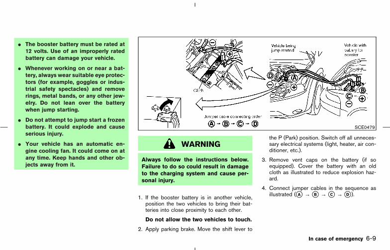
� The booster battery must be rated at12 volts. Use of an improperly ratedbattery can damage your vehicle.
� Whenever working on or near a bat-tery, always wear suitable eye protec-tors (for example, goggles or indus-trial safety spectacles) and removerings, metal bands, or any other jew-elry. Do not lean over the batterywhen jump starting.
� Do not attempt to jump start a frozenbattery. It could explode and causeserious injury.
� Your vehicle has an automatic en-gine cooling fan. It could come on atany time. Keep hands and other ob-jects away from it.
WARNING
Always follow the instructions below.Failure to do so could result in damageto the charging system and cause per-sonal injury.
1. If the booster battery is in another vehicle,position the two vehicles to bring their bat-teries into close proximity to each other.
Do not allow the two vehicles to touch.
2. Apply parking brake. Move the shift lever to
the P (Park) position. Switch off all unneces-sary electrical systems (light, heater, air con-ditioner, etc.).
3. Remove vent caps on the battery (if soequipped). Cover the battery with an oldcloth as illustrated to reduce explosion haz-ard.
4. Connect jumper cables in the sequence asillustrated (�A → �B → �C → �D ).
SCE0479
In case of emergency 6-9
� 04.8.3/Z50-D/V5.0 �

CAUTION
� Always connect positive (+) to posi-tive (+) and negative (−) to bodyground (for example, strut mountingbolt, engine lift bracket, etc. — not tothe battery).
� Make sure that jumper cables do nottouch moving parts in the enginecompartment and that the cableclamps do not contact any othermetal.
5. Start the engine of the other vehicle and let itrun for a few minutes.
6. Keep the engine speed of the other vehicle atabout 2,000 rpm, and start your engine in thenormal manner.
CAUTION
Do not keep the starter motor engagedfor more than 10 seconds. If the enginedoes not start right away, turn the keyoff and wait 3 to 4 seconds before trying
again.
7. After starting your engine, carefully discon-nect the negative cable and then the positivecable.
8. Replace the vent caps (if so equipped). Besure to dispose of the cloth used to cover thevent holes as it may be contaminated withcorrosive acid.
Do not start the engine by pushing.
CAUTION
CVT models cannot be push started.Attempting to do so may cause trans-mission damage.
PUSH STARTING
6-10 In case of emergency
� 04.8.3/Z50-D/V5.0 �

WARNING
� Do not continue to drive if your ve-hicle overheats. Doing so couldcause engine damage or a vehiclefire.
� To avoid the danger of being scalded,never remove the radiator cap whilethe engine is still hot. When the ra-diator cap is removed, pressurizedhot water will spurt out, possiblycausing serious injury.
� Do not open the hood if steam iscoming out.
If your vehicle is overheating (indicated by anextremely high temperature gauge reading), or ifyou feel a lack of engine power, detect abnormalnoise, etc., take the following steps:
1. Move the vehicle safely off the road, apply theparking brake and move the shift lever to theP (Park) position.
Do not stop the engine.
2. Turn off the air conditioner switch. Open allthe windows, move the heater or air condi-
tioner temperature control to maximum hotand fan control to high speed.
3. If engine overheating is caused by climbing along hill on a hot day, run the engine at a fastidle (approximately 1,500 rpm) until the tem-perature gauge indication returns to normal.
4. Get out of the vehicle. Look and listen forsteam or coolant escaping from the radiatorbefore opening the hood. (If steam or coolantis escaping, turn off the engine.) Do not openthe hood further until no steam or coolant canbe seen.
5. Open the engine hood.
WARNING
If steam or water is coming from theengine, stand clear to prevent gettingburned.
6. Visually check if the cooling fan is running.The radiator hoses and radiator should notleak water.
If coolant is leaking or the cooling fan doesnot run, stop the engine.
WARNING
� Be careful not to allow your hands,hair, jewelry or clothing to come intocontact with, or get caught in, drivebelt, or cooling fan.
� The engine cooling fan can start atany time when the coolant tempera-ture is high.
7. After the engine cools down, check the cool-ant level in the reservoir tank with the enginerunning. Add coolant to the reservoir tank ifnecessary. Have your vehicle repaired at thenearest NISSAN dealer.
IF YOUR VEHICLE OVERHEATS
In case of emergency 6-11
� 04.8.3/Z50-D/V5.0 �

When towing your vehicle, all State, provincialand local regulations for towing must be fol-lowed. Incorrect towing equipment could dam-age your vehicle. Towing instructions are avail-able from a NISSAN dealer. Local serviceoperators are generally familiar with the appli-cable laws and procedures for towing. To assureproper towing and to prevent accidental damageto your vehicle, NISSAN recommends having aservice operator tow your vehicle. It is advisableto have the service operator carefully read thefollowing precautions.
WARNING
� Never ride in a vehicle that is beingtowed.
� Never get under your vehicle after ithas been lifted by a tow truck.
CAUTION
� When towing, make sure that thetransmission, axles, steering systemand powertrain are in working condi-tion. If any unit is damaged, dollies
must be used.
� Always attach safety chains beforetowing.
TOWING YOUR VEHICLE
6-12 In case of emergency
� 04.8.3/Z50-D/V5.0 �
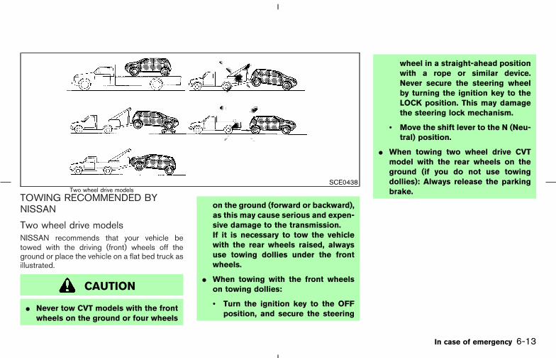
TOWING RECOMMENDED BYNISSAN
Two wheel drive modelsNISSAN recommends that your vehicle betowed with the driving (front) wheels off theground or place the vehicle on a flat bed truck asillustrated.
CAUTION
� Never tow CVT models with the frontwheels on the ground or four wheels
on the ground (forward or backward),as this may cause serious and expen-sive damage to the transmission.If it is necessary to tow the vehiclewith the rear wheels raised, alwaysuse towing dollies under the frontwheels.
� When towing with the front wheelson towing dollies:
• Turn the ignition key to the OFFposition, and secure the steering
wheel in a straight-ahead positionwith a rope or similar device.Never secure the steering wheelby turning the ignition key to theLOCK position. This may damagethe steering lock mechanism.
• Move the shift lever to the N (Neu-tral) position.
� When towing two wheel drive CVTmodel with the rear wheels on theground (if you do not use towingdollies): Always release the parkingbrake.
SCE0438Two wheel drive models
In case of emergency 6-13
� 04.8.3/Z50-D/V5.0 �

All wheel drive modelsNISSAN recommends that towing dollies beused when towing your vehicle or the vehicle beplaced on a flat bed truck as illustrated.
CAUTION
Never tow CVT AWD models with any ofthe wheels on the ground as this maycause serious and expensive damage tothe drive train.
VEHICLE RECOVERY (Freeing astuck vehicle)
�1 Remove the hook cover from the bumperusing a suitable tool.
�2 Securely install the hook. (Towing hook isstored with jacking tools.)
Make sure that the hook is properly secured inthe stored place after use.
SCE0439All wheel drive models
SCE0531
6-14 In case of emergency
� 04.8.3/Z50-D/V5.0 �

WARNING
� Stand clear of a stuck vehicle.
� Do not spin your tires at high speed.This could cause them to explodeand result in serious injury. Parts ofyour vehicle could also overheat andbe damaged.
CAUTION
� Tow chains or cables must be at-tached only to the vehicle recoveryhooks or main structural members ofthe vehicle. Otherwise, the vehiclebody will be damaged.
� Never tow a vehicle using the vehicletie downs or recovery hooks.
� Always pull the cable straight outfrom the front or rear of the vehicle.Never pull the vehicle at an angle.
� Pulling devices should be routed sothey do not touch any part of thesuspension, steering, brake or cool-ing systems.
� Pull devices such as ropes or canvasstraps are not recommended for usein vehicle towing or recovery.
If your vehicle is stuck in sand, snow, mud, etc.,use the following procedure:
1. Turn off the Vehicle Dynamic Control (VDC)system.
2. Make sure the area in front and behind thevehicle is clear of obstructions.
3. Turn the steering wheel right and left to clearan area around the front tires.
4. Slowly rock the vehicle forward and back-ward.
� Shift back and forth between R (reverse) andD (drive).
� Apply the accelerator as little as possible tomaintain the rocking motion.
� Release the accelerator pedal before shiftingbetween R and D.
� Do not spin the tires above 35 MPH (55km/h).
5. If the vehicle cannot be freed after a few tries,contact a professional towing service to re-move the vehicle.
SCE0444Tie down and recovery hook
In case of emergency 6-15
� 04.8.3/Z50-D/V5.0 �

MEMO
6-16 In case of emergency
� 04.8.3/Z50-D/V5.0 �

7 Appearance and care
Cleaning exterior .................................................................... 7-2Washing ............................................................................. 7-2Waxing ................................................................................ 7-2Removing spots................................................................ 7-3Underbody ......................................................................... 7-3Glass ................................................................................... 7-3Aluminum alloy wheels.................................................... 7-3Chrome parts .................................................................... 7-3
Cleaning interior ..................................................................... 7-3
Floor mats .......................................................................... 7-4Seat belts ........................................................................... 7-4
Corrosion protection ............................................................. 7-5Most common factors contributing to vehiclecorrosion............................................................................. 7-5Environmental factors influence the rate ofcorrosion............................................................................. 7-5To protect your vehicle from corrosion ...................... 7-5
� 04.8.3/Z50-D/V5.0 �
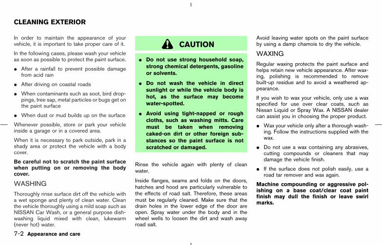
In order to maintain the appearance of yourvehicle, it is important to take proper care of it.
In the following cases, please wash your vehicleas soon as possible to protect the paint surface.
� After a rainfall to prevent possible damagefrom acid rain
� After driving on coastal roads
� When contaminants such as soot, bird drop-pings, tree sap, metal particles or bugs get onthe paint surface
� When dust or mud builds up on the surface
Whenever possible, store or park your vehicleinside a garage or in a covered area.
When it is necessary to park outside, park in ashady area or protect the vehicle with a bodycover.
Be careful not to scratch the paint surfacewhen putting on or removing the bodycover.
WASHINGThoroughly rinse surface dirt off the vehicle witha wet sponge and plenty of clean water. Cleanthe vehicle thoroughly using a mild soap such asNISSAN Car Wash, or a general purpose dish-washing liquid mixed with clean, lukewarm(never hot) water.
CAUTION
� Do not use strong household soap,strong chemical detergents, gasolineor solvents.
� Do not wash the vehicle in directsunlight or while the vehicle body ishot, as the surface may becomewater-spotted.
� Avoid using tight-napped or roughcloths, such as washing mitts. Caremust be taken when removingcaked-on dirt or other foreign sub-stances so the paint surface is notscratched or damaged.
Rinse the vehicle again with plenty of cleanwater.
Inside flanges, seams and folds on the doors,hatches and hood are particularly vulnerable tothe effects of road salt. Therefore, these areasmust be regularly cleaned. Make sure that thedrain holes in the lower edge of the door areopen. Spray water under the body and in thewheel wells to loosen the dirt and wash awayroad salt.
Avoid leaving water spots on the paint surfaceby using a damp chamois to dry the vehicle.
WAXINGRegular waxing protects the paint surface andhelps retain new vehicle appearance. After wax-ing, polishing is recommended to removebuilt-up residue and to avoid a weathered ap-pearance.
If you wish to wax your vehicle, only use a waxspecified for use over clear coats, such asNissan Liquid or Spray Wax. A NISSAN dealercan assist you in choosing the proper product.
� Wax your vehicle only after a thorough wash-ing. Follow the instructions supplied with thewax.
� Do not use a wax containing any abrasives,cutting compounds or cleaners that maydamage the vehicle finish.
� If the surface does not polish easily, use aroad tar remover and wax again.
Machine compounding or aggressive pol-ishing on a base coat/clear coat paintfinish may dull the finish or leave swirlmarks.
CLEANING EXTERIOR
7-2 Appearance and care
� 04.8.3/Z50-D/V5.0 �

REMOVING SPOTS
Remove tar and oil spots, industrial dust, insects,and tree sap as quickly as possible from thesurface of the paint to avoid lasting damage orstaining. Special cleaning products are availableat a NISSAN dealer or any automotive accessorystore.
UNDERBODYIn areas where road salt is used in winter, theunderbody must be cleaned regularly. This willprevent dirt and salt from building up and caus-ing underbody and suspension corrosion. Be-fore the winter period and again in the spring, theunderseal must be checked and, if necessary,re-treated.
GLASSUse glass cleaner to remove smoke and dust filmfrom the glass surfaces. It is normal for glass tobecome coated with a film after the vehicle isparked in the hot sun. Glass cleaner and a softcloth will easily remove this film.
CAUTION
When cleaning the inside of the win-dow, do not use sharp-edged tools,
abrasive cleaners or chlorine-based dis-infectant cleaners. They could damagethe electrical conductors, radio antennaelements or rear window defroster ele-ments.
ALUMINUM ALLOY WHEELSWash regularly, especially during winter monthsin areas where road salt is used. Salt coulddiscolor the wheel if not removed.
CHROME PARTSClean all chrome parts regularly with a non-abrasive chrome polish to maintain the finish.
Occasionally remove loose dust from the interiortrim, plastic parts and seats using a vacuumcleaner or soft brush. Wipe the vinyl and leathersurfaces with a clean, soft cloth dampened inmild soap solution, then wipe clean with a drysoft cloth. Before using any fabric protector,read the manufacturer’s recommendations.Some fabric protectors contain chemicals thatmay stain or bleach the seat material.
Use a cloth dampened only with water, to cleanthe meter and gauge lens.
CAUTION
� Never use benzine, thinner, or anysimilar material.
� The leather seats should be regularlycoated with a leather wax like saddlesoap. Never use car wax.
� Never use fabric protectors unlessrecommended by the manufacturer.
� Do not use glass or plastic cleaner onmeter or gauge lens covers. It maydamage the lens cover.
CLEANING INTERIOR
Appearance and care 7-3
� 04.8.3/Z50-D/V5.0 �

FLOOR MATSThe use of Genuine NISSAN floor mats canextend the life of your vehicle carpet and make iteasier to clean the interior. No matter whatmats are used, be sure they are fitted foryour vehicle and are properly positioned inthe footwell to prevent interference withpedal operation. Mats should be maintainedwith regular cleaning and replaced if they be-come excessively worn.
Floor mat positioning aid(Driver side only)This model includes a front floor mat bracket �Ato act as a floor mat positioning aid. NISSANfloor mats have been specially designed for yourvehicle model. The driver’s side floor mat has agrommet hole incorporated in it. Simply positionthe mat by placing the floor mat bracket throughthe floor mat grommet hole while centering themat in the floorpan contour.
Periodically check to make certain that the matsare properly positioned.
SEAT BELTSThe seat belts can be cleaned by wiping themwith a sponge dampened in a mild soap solution.Allow the belts to dry completely before usingthem.
WARNING
Do not allow wet seat belts to roll up inthe retractor. NEVER use bleach, dye orchemical solvents to clean the seatbelts, since these materials may se-verely weaken the seat belt webbing.SAI0030
7-4 Appearance and care
� 04.8.3/Z50-D/V5.0 �

MOST COMMON FACTORSCONTRIBUTING TO VEHICLECORROSION:� The accumulation of moisture-retaining dirt
and debris in body panel sections, cavities,and other areas.
� Damage to paint and other protective coat-ings caused by gravel and stone chips orminor traffic accidents.
ENVIRONMENTAL FACTORSINFLUENCE THE RATE OFCORROSION:
MoistureAccumulation of sand, dirt and water on thevehicle body underside can accelerate corro-sion. Wet floor coverings will not dry completelyinside the vehicle, and should be removed fordrying to avoid floor panel corrosion.
Relative humidityCorrosion will be accelerated in areas of highrelative humidity, especially those areas wherethe temperatures stay above freezing and whereatmospheric pollution exists and road salt isused.
TemperatureA temperature increase will accelerate the rateof corrosion to those parts which are not wellventilated.
Air pollutionIndustrial pollution, the presence of salt in the airin coastal areas, or heavy road salt use willaccelerate the corrosion process. Road salt willalso accelerate the disintegration of paint sur-faces.
TO PROTECT YOUR VEHICLEFROM CORROSION:� Wash and wax your vehicle often to keep the
vehicle clean.
� Always check for minor damage to the paintand repair it as soon as possible.
� Keep drain holes at the bottom of the doorsopen to avoid water accumulation.
� Check the underbody for accumulation ofsand, dirt or salt. If present, wash with wateras soon as possible.
CAUTION
� NEVER remove dirt, sand or otherdebris from the passenger compart-ment by washing it out with a hose.Remove dirt with a vacuum cleaner orbroom.
� Never allow water or other liquids tocome in contact with electronic com-ponents inside the vehicle as thismay damage them.
Chemicals used for road surface de-icing areextremely corrosive. They accelerate corrosionand deterioration of underbody componentssuch as the exhaust system, fuel and brake lines,brake cables, floor pan and fenders.
In winter, the underbody must be cleanedperiodically.
For additional protection against rust and corro-sion, which may be required in some areas,consult a NISSAN dealer.
CORROSION PROTECTION
Appearance and care 7-5
� 04.8.3/Z50-D/V5.0 �

MEMO
7-6 Appearance and care
� 04.8.3/Z50-D/V5.0 �
8 Maintenance and do-it-yourself
Maintenance requirements .................................................. 8-2General maintenance ............................................................ 8-2
Explanation of general maintenance items ................ 8-2Maintenance precautions..................................................... 8-5Engine compartment check locations ............................. 8-7Engine cooling system.......................................................... 8-8
Checking engine coolant level...................................... 8-8Changing engine coolant ............................................... 8-9
Engine oil ................................................................................. 8-9Checking engine oil level ............................................... 8-9Changing engine oil...................................................... 8-10Changing engine oil filter ............................................ 8-11
CVT fluid................................................................................ 8-12Power steering fluid............................................................ 8-12Brake fluid ............................................................................. 8-13Window washer fluid.......................................................... 8-14Battery .................................................................................... 8-14
Jump starting .................................................................. 8-15Drive belts ............................................................................. 8-16Spark plugs........................................................................... 8-16
Replacing spark plugs.................................................. 8-17Air cleaner ............................................................................. 8-17Windshield wiper blades................................................... 8-18
Cleaning........................................................................... 8-18Replacing......................................................................... 8-18
Rear window wiper blade ................................................. 8-20Parking brake and brake pedal........................................ 8-20
Checking parking brake............................................... 8-20Checking brake pedal .................................................. 8-20Brake booster ................................................................. 8-21
Fuses ...................................................................................... 8-21Engine compartment..................................................... 8-22Passenger compartment.............................................. 8-23
Battery replacement............................................................ 8-24Keyfob ............................................................................. 8-24Intelligent key .................................................................. 8-25
Lights ..................................................................................... 8-26Headlights ...................................................................... 8-27Exterior and interior lights............................................ 8-28
Wheels and tires ................................................................. 8-29Tire pressure................................................................... 8-29Tire labeling..................................................................... 8-32Types of tires .................................................................. 8-33Tire chains ....................................................................... 8-34Changing wheels and tires ......................................... 8-35
� 04.8.3/Z50-D/V5.0 �
Your new NISSAN has been designed to haveminimum maintenance requirements with longerservice intervals to save you both time andmoney. However, some day-to-day and regularmaintenance is essential to maintain yourNISSAN’s good mechanical condition, as wellas its emission and engine performance.
It is the owner’s responsibility to make sure thatscheduled maintenance, as well as generalmaintenance, is performed.
As the vehicle owner, you are the only one whocan ensure that your vehicle receives the propermaintenance care. You are a vital link in themaintenance chain.
Scheduled maintenance:
For your convenience, both required and op-tional scheduled maintenance items are de-scribed and listed in your “Service and Mainte-nance Guide”. You must refer to that guide toensure that necessary maintenance is performedon a NISSAN at regular intervals.
General maintenance:
General maintenance includes those itemswhich should be checked during normal day-to-day operation. They are essential for propervehicle operation. It is your responsibility toperform these procedures regularly as pre-scribed.
Performing general maintenance checks requireminimal mechanical skill and only a few generalautomotive tools.
These checks or inspections can be done byyourself, a qualified technician or, if you prefer, aNISSAN dealer.
Where to go for service:
If maintenance service is required or your vehicleappears to malfunction, have the systemschecked and tuned by a NISSAN dealer.
NISSAN technicians are well-trained specialistsand are kept up to date with the latest serviceinformation through technical bulletins, servicetips, and in-dealership training programs. Theyare completely qualified to work on NISSANvehicles before they work on your vehicle,rather than after they have worked on it.
You can be confident that a NISSAN dealer’sservice department performs the best job tomeet the maintenance requirements of your ve-hicle — in a reliable and economic way.
During the normal day-to-day operation of thevehicle, general maintenance should be per-formed regularly as prescribed in this section. Ifyou detect any unusual sounds, vibrations orsmell, be sure to check for the cause or have aNISSAN dealer check it promptly. In addition,you should notify a NISSAN dealer if you thinkthat repairs are required.
When performing any checks or maintenancework, closely observe the “Maintenance precau-tions” later in this section.
EXPLANATION OF GENERALMAINTENANCE ITEMSAdditional information on the followingitems with “*” is found later in this section.
Outside the vehicleThe maintenance items listed here should beperformed from time to time, unless otherwisespecified.
Doors and engine hood: Check that all doorsand the engine hood operate smoothly. Alsomake sure that all latches lock securely. Lubri-cate if necessary. Make sure that the secondarylatch keeps the hood from opening when theprimary latch is released.
When driving in areas using road salt or othercorrosive materials, check lubrication frequently.
MAINTENANCE REQUIREMENTS GENERAL MAINTENANCE
8-2 Maintenance and do-it-yourself
� 04.8.3/Z50-D/V5.0 �

Lights*: Clean the headlights on a regular basis.Make sure that the headlights, stop lights, taillights, turn signal lights, and other lights are alloperating properly and installed securely. Alsocheck headlight aim.
Road wheel nuts (lug nuts)*:When checkingthe tires, make sure no wheel nuts are missing,and check for any loose wheel nuts. Tighten ifnecessary.
Tire rotation*: Tires should be rotated every7,500 miles (12,000 km). However, the timingfor tire rotation may vary according to yourdriving habits and road surface conditions.
Tires*: Check the pressure with a gauge oftenand always prior to long distance trips. If neces-sary, adjust the pressure in all tires, including thespare, to the pressure specified. Check carefullyfor damage, cuts or excessive wear.
Tire, wheel alignment and balance: If thevehicle should pull to either side while driving ona straight and level road, or if you detect unevenor abnormal tire wear, there may be a need forwheel alignment.
If the steering wheel or seat vibrates at normalhighway speeds, wheel balancing may beneeded.
For additional information regarding tires, refer to“Important Tire Safety Information” (US) or “Tire
Safety Information” (Canada) in the WarrantyInformation Booklet.
Windshield: Clean the windshield on a regularbasis. Check the windshield at least every sixmonths for cracks or other damage. Have adamaged windshield repaired by a qualified re-pair facility.
Windshield wiper blades*: Check for cracksor wear if they do not wipe properly.
Inside the vehicleThe maintenance items listed here should bechecked on a regular basis, such as whenperforming periodic maintenance, cleaning thevehicle, etc.
Accelerator pedal: Check the pedal forsmooth operation and make sure the pedal doesnot catch or require uneven effort. Keep the floormats away from the pedal.
Brake pedal and booster*: Check the pedalfor smooth operation and make sure it has theproper distance under it when depressed fully.Check the brake booster function. Be sure tokeep floor mats away from the pedal.
Brakes: Check that the brakes do not pull thevehicle to one side when applied.
Continuously Variable Transmission (CVT)P (Park) position mechanism: On a fairly
steep hill check that the vehicle is held securelywith the shift lever in the P (Park) positionwithout applying any brakes.
Parking brake*: Check that the lever has theproper travel and make sure that the vehicle isheld securely on a fairly steep hill when only theparking brake is applied.
Seat belts: Check that all parts of the seat beltsystem (for example, buckles, anchors, adjustersand retractors) operate properly and smoothly,and are installed securely. Check the belt web-bing for cuts, fraying, wear or damage.
Seats: Check seat position controls such asseat adjusters, seatback recliner, etc. to ensurethey operate smoothly and that all latches locksecurely in every position. Check that the headrestraints move up and down smoothly and thatthe locks hold securely in all latched positions.
Steering wheel: Check for changes in thesteering conditions, such as excessive free play,hard steering or strange noises.
Warning lights and chimes:Make sure that allwarning lights and chimes are operating prop-erly.
Windshield defroster: Check that the aircomes out of the defroster outlets properly andin good quantity when operating the heater or airconditioner.
Maintenance and do-it-yourself 8-3
� 04.8.3/Z50-D/V5.0 �
Windshield wiper and washer*: Check thatthe wipers and washer operate properly and thatthe wipers do not streak.
Under the hood and the vehicleThe maintenance items listed here should bechecked periodically (for example, each time youcheck the engine oil or refuel).
Battery*: Check the fluid level in each cell. Itshould be between the MAX and MIN lines.Vehicles operated in high temperatures or undersevere conditions require frequent checks of thebattery fluid level.
Brake fluid level*: Make sure that the brakefluid level is between the MAX and MIN lines onthe reservoir.
Engine coolant level*: Check the coolant levelwhen the engine is cold.
Engine drive belts*: Make sure that no belt isfrayed, worn, cracked or oily.
Engine oil level*: Check the level on thedipstick after parking the vehicle on a level spotand turning off the engine.
Exhaust system: Make sure there are no loosesupports, cracks or holes. If the sound of theexhaust seems unusual or there is a smell ofexhaust fumes, immediately locate the troubleand correct it. (See “Precautions when starting
and driving” in the “5. Starting and driving”section for exhaust gas (carbon monoxide).)
Fluid leaks: Check under the vehicle for fuel,oil, water or other fluid leaks after the vehicle hasbeen parked for a while. Water dripping from theair conditioner after use is normal. If you shouldnotice any leaks or if gasoline fumes are evident,check for the cause and have it corrected imme-diately.
Power steering fluid level* and lines: Checkthe level in the reservoir tank with the engine off.Check the lines for proper attachment, leaks,cracks, etc.
Radiator and hoses: Check the front of theradiator and clean off any dirt, insects, leaves,etc., that may have accumulated. Make sure thehoses have no cracks, deformation, deteriorationor loose connections.
Underbody: The underbody is frequently ex-posed to corrosive substances such as thoseused on icy roads or to control dust. It is veryimportant to remove these substances, other-wise rust will form on the floor pan, frame, fuellines and around the exhaust system. At the endof winter, the underbody should be thoroughlyflushed with plain water, being careful to cleanthose areas where mud and dirt may accumu-late. For additional information, see “Cleaning
exterior” in the “7. Appearance and care” sec-tion.
Windshield washer fluid*: Check that there isadequate fluid in the tank.
8-4 Maintenance and do-it-yourself
� 04.8.3/Z50-D/V5.0 �
When performing any inspection or maintenancework on your vehicle, always take care to preventserious accidental injury to yourself or damage tothe vehicle. The following are general precau-tions which should be closely observed.
WARNING
� Park the vehicle on a level surface,apply the parking brake securely andblock the wheels to prevent the ve-hicle from moving. Move the selectorlever to the P (Park) position.
� Be sure the ignition key is in the OFFor LOCK position when performingany parts replacement or repairs.
� Your vehicle is equipped with an au-tomatic engine cooling fan. It maycome on at any time without warning,even if the ignition key is in the OFFposition and the engine is not run-ning. To avoid injury, always discon-nect the negative battery cable be-fore working near the fan.
� If you must work with the enginerunning, keep your hands, clothing,
hair and tools away from movingfans, belts and any other movingparts.
� It is advisable to secure or removeany loose clothing and remove anyjewelry, such as rings, watches, etc.before working on your vehicle.
� Always wear eye protection when-ever you work on your vehicle.
� If you must run the engine in anenclosed space such as a garage, besure there is proper ventilation forexhaust gases to escape.
� Never get under the vehicle while it issupported only by a jack. If it is nec-essary to work under the vehicle,support it with safety stands.
� Keep smoking materials, flame andsparks away from fuel tank and bat-tery.
� On gasoline engine models with theMultiport Fuel Injection (MFI) Sys-tem, the fuel filter or fuel lines should
be serviced by a NISSAN dealer be-cause the fuel lines are under highpressure even when the engine is off.
CAUTION
� Do not work under the hood whilethe engine is hot. Turn the engine offand wait until it cools down.
� Never connect or disconnect the bat-tery or any transistorized componentwhile the ignition switch is in the ONposition.
� Never leave the engine or the CVTrelated component harness connec-tor disconnected while the ignitionswitch is in the ON position.
� Avoid contact with used engine oiland coolant. Improperly disposed en-gine oil, engine coolant and/or othervehicle fluids can damage the envi-ronment. Always conform to localregulations for disposal of vehiclefluid.
MAINTENANCE PRECAUTIONS
Maintenance and do-it-yourself 8-5
� 04.8.3/Z50-D/V5.0 �
This “8. Maintenance and do-it-yourself” sectiongives instructions regarding only those itemswhich are relatively easy for an owner to perform.
A genuine NISSAN Service Manual is also avail-able. See “Owner’s Manual/Service Manual or-der information” in the “9. Technical and con-sumer information” section.
You should be aware that incomplete or im-proper servicing may result in operating difficul-ties or excessive emissions, and could affectyour warranty coverage. If in doubt about anyservicing, have it done by a NISSAN dealer.
8-6 Maintenance and do-it-yourself
� 04.8.3/Z50-D/V5.0 �

1. Power steering fluid reservoir
2. Engine oil filler cap
3. Brake fluid reservoir
4. Air cleaner
5. Windshield washer fluid reservoir
6. Engine coolant reservoir
7. Drive belts
8. Radiator filler cap
9. Engine oil dipstick
10. Fuse/fusible link holder
11. Battery
SDI1760
ENGINE COMPARTMENT CHECKLOCATIONS
Maintenance and do-it-yourself 8-7
� 04.8.3/Z50-D/V5.0 �

The engine cooling system is filled at the factorywith a high-quality, year-round, antifreeze cool-ant solution. The antifreeze solution contains rustand corrosion inhibitors, therefore additionalcooling system additives are not necessary.
WARNING
� Never remove the radiator cap whenthe engine is hot. Wait until the en-gine and radiator cool down. Seriousburns could be caused by high pres-sure fluid escaping from the radiator.Wait until the engine and radiatorcool down.
� See “If your vehicle overheats” in the“In case of emergency” section ofthis manual.
� The radiator is equipped with a pres-sure type radiator cap. To preventengine damage, use only a genuineNISSAN radiator cap.
CAUTION
When adding or replacing coolant, besure to use only a Genuine NISSANLong Life Antifreeze/Coolant (green) orequivalent with the proper mixture ratioof 50% anti-freeze and 50% demineral-ized or distilled water. The use of othertypes of engine coolant may damagethe cooling system.
Outside temperaturedown to Anti-
freeze
Deminer-alizedwater/distilledwater°C °F
−35 −30 50% 50%
CHECKING ENGINE COOLANTLEVELCheck the coolant level in the reservoir tankwhen the engine is cold. If the coolant level isbelow MIN �2 , open the reservoir tank cap �Aand add coolant up to the MAX �1 level. If thereservoir tank is empty, add the coolant to thereservoir tank up to the MAX �1 level.
If the engine cooling system frequentlyrequires coolant, have it checked by aNISSAN dealer.
SDI1761
ENGINE COOLING SYSTEM
8-8 Maintenance and do-it-yourself
� 04.8.3/Z50-D/V5.0 �

CHANGING ENGINE COOLANTContact a NISSAN dealer if replacement isrequired.
� Major cooling system repairs should be per-formed by a NISSAN dealer. The serviceprocedures can be found in the appropriateNISSAN Service Manual.
� Improper servicing can result in reducedheater performance and engine overheating.
WARNING
� To avoid being scalded, never changethe coolant when the engine is hot.
� Never remove the radiator cap whenthe engine is hot. Serious burnscould be caused by high pressurefluid escaping from the radiator.
� Avoid direct skin contact with usedcoolant. If skin contact is made, washthoroughly with soap or hand cleaneras soon as possible.
� Keep coolant out of reach of childrenand pets.
CHECKING ENGINE OIL LEVEL1. Park the vehicle on a level surface and apply
parking brake.
2. Run the engine until it reaches operatingtemperature.
3. Turn off the engine. Wait more than 10minutes for the oil to drain back into theoil pan.
4. Remove the dipstick as illustrated and wipe itclean. Reinsert it all the way.
5. Remove the dipstick again and check the oillevel. It should be between the H and L marks�1 . If the oil level is below the L mark �2 ,remove the oil filler cap and pour recom-mended oil through the opening. Do notoverfill �3 .
6. Recheck oil level with dipstick.
It is normal to add some oil between oilmaintenance intervals or during thebreak-in period, depending on the severityof operating conditions.
CAUTION
Oil level should be checked regularly.Operating the engine with an insuffi-cient amount of oil can damage theengine, and such damage is not coveredby warranty.
SDI1762
ENGINE OIL
Maintenance and do-it-yourself 8-9
� 04.8.3/Z50-D/V5.0 �

CHANGING ENGINE OIL
Change the engine oil and filter according to themaintenance log shown in the Service and Main-tenance Guide.
1. Park the vehicle on a level surface and applythe parking brake.
2. Run the engine until it reaches operatingtemperature.
3. Turn the engine off and wait more than 10minutes.
4. Place a large drain pan under the drain plug�A (under the body).
5. Remove the oil filler cap �B (inside the enginecompartment).
6. Remove the drain plug �A with a wrench andcompletely drain the oil.
If oil filter is to be changed, remove andreplace it at this time. See later in “Engine oil”for changing engine oil filter.
CAUTION
Be careful not to burn yourself, as theengine oil is hot.
� Waste oil must be disposed of properly.
� Check your local regulations.
7. Clean and re-install the drain plug with a new
washer. Securely tighten the drain plug with awrench.
Drain plug tightening torque:
22 to 29 ft-lb (29 to 39 N⋅m)
Do not use excessive force.
8. Refill engine with recommended oil and in-stall the cap securely.
CAUTION
Never pull out the oil level gauge whilefilling engine oil.
See “Capacities and recommendedfuel/lubricants” in the “9. Technical and con-sumer information” section for drain and refillcapacity. The drain and refill capacity de-pends on the oil temperature and drain time.Use these specifications for reference only.Always use the dipstick to determine theproper amount of oil in the engine.
9. Start the engine.
Check for leakage around the drain plug.Correct as required.
10. Turn the engine off and wait more than 10minutes. Check the oil level with the dip-
SDI1763
8-10 Maintenance and do-it-yourself
� 04.8.3/Z50-D/V5.0 �

stick. Add engine oil if necessary.
11. Dispose of waste oil properly.
WARNING
� Prolonged and repeated contact withused engine oil may cause skin can-cer.
� Try to avoid direct skin contact withused oil. If skin contact is made,wash thoroughly with soap or handcleaner as soon as possible.
� Keep used engine oil out of reach ofchildren.
CHANGING ENGINE OIL FILTER
1. Park the vehicle on a level surface and applythe parking brake.
2. Turn the engine off.
3. Remove the cover with a suitable tool asillustrated �A .
4. Loosen the oil filter �B with an oil filterwrench. Remove the oil filter by turning it byhand.
CAUTION
Be careful not to burn yourself, as theengine oil may be hot.
5. Wipe the engine oil filter mounting surfacewith a clean rag.
Be sure to remove any old rubber gasketremaining on the mounting surface of theengine.
6. Coat the rubber gasket on the new filter withclean engine oil.
7. Screw in the oil filter until a slight resistanceis felt, then tighten additionally more than 2/3turn.
Oil filter tightening torque:
11 to 15 ft-lb (15 to 20 N⋅m)
8. Reinstall the cover.
9. Start the engine and check for leakage
SDI1764
Maintenance and do-it-yourself 8-11
� 04.8.3/Z50-D/V5.0 �

around the oil filter. Correct as required.
10. Turn the engine off and wait several min-utes. Check the oil level. Add engine oil ifnecessary.
Contact a NISSAN dealer if checking or replace-ment is required.
CAUTION
� Use only Genuine NISSAN CVT FluidNS-2. Do not mix with other fluids.
� Using transmission fluid other thanGenuine NISSAN CVT Fluid NS-2 willdamage the CVT transmission, whichis not covered by the NISSAN newvehicle limited warranty.
The specified CVT fluid is also described oncaution labels located in the engine compart-ment.
Check the fluid level in the reservoir tank.
The fluid level should be checked using the HOTrange (�1 : HOT MAX., �2 : HOT MIN.) at fluidtemperatures of 122 to 176°F (50 to 80°C) orusing the COLD range (�3 : COLD MAX., �4 :COLD MIN.) at fluid temperatures of 32 to 86°F(0 to 30°C).
CAUTION
� Do not overfill.
� Use Genuine NISSAN PSF or equiva-
SDI1765A
CVT FLUID POWER STEERING FLUID
8-12 Maintenance and do-it-yourself
� 04.8.3/Z50-D/V5.0 �
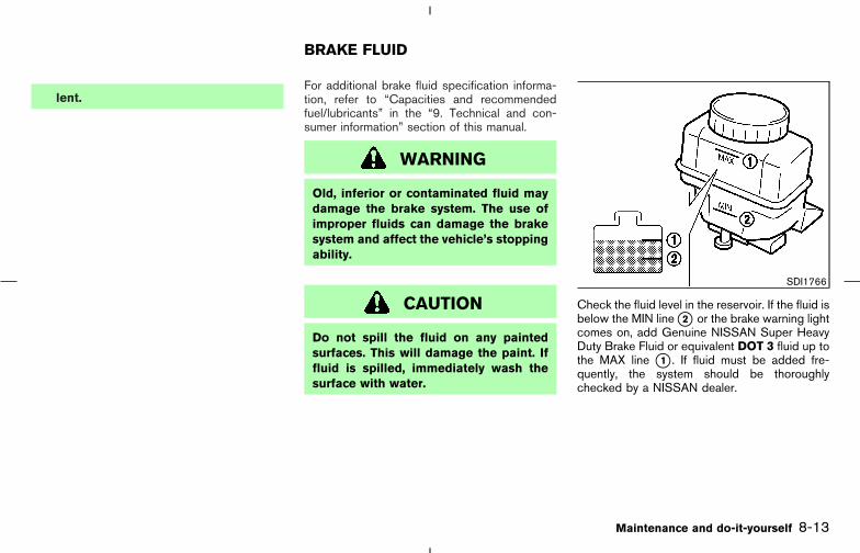
lent.For additional brake fluid specification informa-tion, refer to “Capacities and recommendedfuel/lubricants” in the “9. Technical and con-sumer information” section of this manual.
WARNING
Old, inferior or contaminated fluid maydamage the brake system. The use ofimproper fluids can damage the brakesystem and affect the vehicle’s stoppingability.
CAUTION
Do not spill the fluid on any paintedsurfaces. This will damage the paint. Iffluid is spilled, immediately wash thesurface with water.
Check the fluid level in the reservoir. If the fluid isbelow the MIN line �2 or the brake warning lightcomes on, add Genuine NISSAN Super HeavyDuty Brake Fluid or equivalent DOT 3 fluid up tothe MAX line �1 . If fluid must be added fre-quently, the system should be thoroughlychecked by a NISSAN dealer.
SDI1766
BRAKE FLUID
Maintenance and do-it-yourself 8-13
� 04.8.3/Z50-D/V5.0 �
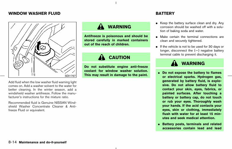
Add fluid when the low washer fluid warning lightcomes on. Add a washer solvent to the water forbetter cleaning. In the winter season, add awindshield washer antifreeze. Follow the manu-facturer’s instructions for the mixture ratio.
Recommended fluid is Genuine NISSAN Wind-shield Washer Concentrate Cleaner & Anti-freeze Fluid or equivalent.
WARNING
Antifreeze is poisonous and should bestored carefully in marked containersout of the reach of children.
CAUTION
Do not substitute engine anti-freezecoolant for window washer solution.This may result in damage to the paint.
� Keep the battery surface clean and dry. Anycorrosion should be washed off with a solu-tion of baking soda and water.
� Make certain the terminal connections areclean and securely tightened.
� If the vehicle is not to be used for 30 days orlonger, disconnect the (—) negative batteryterminal cable to prevent discharging it.
WARNING
� Do not expose the battery to flamesor electrical sparks. Hydrogen gas,generated by battery fluid, is explo-sive. Do not allow battery fluid tocontact your skin, eyes, fabrics, orpainted surfaces. After touching abattery or battery cap, do not touchor rub your eyes. Thoroughly washyour hands. If the acid contacts youreyes, skin or clothing, immediatelyflush with water for at least 15 min-utes and seek medical attention.
� Battery posts, terminals and relatedaccessories contain lead and lead
SDI1767
WINDOW WASHER FLUID BATTERY
8-14 Maintenance and do-it-yourself
� 04.8.3/Z50-D/V5.0 �

compounds. Wash hands after han-dling.
� Do not operate the vehicle if the fluidin the battery is low. Low battery fluidcan cause a higher load on the bat-tery which can generate heat, reducebattery life, and in some cases leadto an explosion.
� When working on or near a battery,always wear suitable eye protectionand remove all jewelry.
� Battery posts, terminals and relatedaccessories contain lead and leadcompounds. Wash hands after han-dling.
� Keep the battery out of the reach ofchildren.
Check the fluid level in each cell. It should bebetween the UPPER LEVEL �1 and LOWERLEVEL �2 lines.
If the side of the battery is not visible, theelectrolyte level can be checked through eachfiller opening as illustrated.
If it is necessary to add fluid, add only distilledwater to bring the level to the indicator in eachfiller opening. Do not overfill.
Vehicles operated in high temperatures or undersevere conditions require frequent checks of thebattery fluid level.
1. Remove the cell plugs �A .
2. Add distilled water up to the UPPER LEVEL�1 .
3. Tighten cell plugs �A .
JUMP STARTINGIf jump starting is necessary, see “Jump starting”in the “6. In case of emergency” section. If theengine does not start by jump starting, thebattery may have to be replaced. Contact aNISSAN dealer.
DI0137MA SDI1480
Maintenance and do-it-yourself 8-15
� 04.8.3/Z50-D/V5.0 �

WARNING
Be sure the ignition key is in the OFF orLOCK position. The engine could rotateunexpectedly.
1. Power steering oil pump2. Idler pulley3. Alternator4. Crankshaft pulley5. Air conditioner compressor�: Tension checking points
Visually inspect each belt for signs of unusualwear, cuts, fraying, oil adhesion or looseness. Ifthe belt is in poor condition or loose, have itreplaced or adjusted by a NISSAN dealer.
Have the belts checked regularly for conditionand tension.
WARNING
Be sure the engine and ignition switchare off and that the parking brake isengaged securely.
CAUTION
Be sure to use the correct socket toremove the spark plugs. An incorrectsocket can damage the spark plugs.SDI0141B
DRIVE BELTS SPARK PLUGS
8-16 Maintenance and do-it-yourself
� 04.8.3/Z50-D/V5.0 �

REPLACING SPARK PLUGS
Platinum-tipped spark plugsIt is not necessary to replace the platinum-tipped�A spark plugs as frequently as the conventionaltype spark plugs since they will last much longer.Follow the maintenance log, but do not reusethem by cleaning or regapping.
If replacement is required, see a NISSAN dealerfor servicing.
Always replace with recommendedplatinum-tipped spark plugs.
To remove the filter from the air cleaner, pushdown the lock pins �1 and pull the unit upward�2 .
The filter element should not be cleaned andreused. Replace it according to the maintenancelog shown in the separate Service and Mainte-nance Guide. When replacing the filter, wipe theinside of the air cleaner housing and the coverwith a damp cloth.
WARNING
� Operating the engine with the air
cleaner removed can cause you orothers to be burned. The air cleanernot only cleans the air, it stops theflame if the engine backfires. If it isn’tthere, and the engine backfires, youcould be burned. Do not drive withthe air cleaner removed, and be care-ful when working on the engine withthe air cleaner removed.
� Never pour fuel into the throttle bodyor attempt to start the engine withthe air cleaner removed. Doing socould result in serious injury.
SDI0145C SDI1495
AIR CLEANER
Maintenance and do-it-yourself 8-17
� 04.8.3/Z50-D/V5.0 �
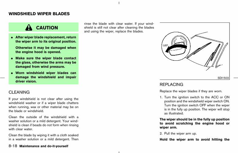
CAUTION
� After wiper blade replacement, returnthe wiper arm to its original position.
Otherwise it may be damaged whenthe engine hood is opened.
� Make sure the wiper blade contactthe glass, otherwise the arms may bedamaged from wind pressure.
� Worn windshield wiper blades candamage the windshield and impairdriver vision.
CLEANING
If your windshield is not clear after using thewindshield washer or if a wiper blade chatterswhen running, wax or other material may be onthe blade or windshield.
Clean the outside of the windshield with awasher solution or a mild detergent. Your wind-shield is clean if beads do not form when rinsingwith clear water.
Clean the blade by wiping it with a cloth soakedin a washer solution or a mild detergent. Then
rinse the blade with clear water. If your wind-shield is still not clear after cleaning the bladesand using the wiper, replace the blades.
REPLACING
Replace the wiper blades if they are worn.
1. Turn the ignition switch to the ACC or ONposition and the windshield wiper switch ON.Turn the ignition switch OFF when the wiperis in the fully up position. The wiper will stopas illustrated.
The wiper should be in the fully up positionto avoid scratching the engine hood orwiper arm.
2. Pull the wiper arm up.
Hold the wiper arm to avoid hitting the
SDI1503
WINDSHIELD WIPER BLADES
8-18 Maintenance and do-it-yourself
� 04.8.3/Z50-D/V5.0 �

windshield and damaging the glass.
3. Push the release tab �A , and then move thewiper blade down the wiper arm �1 whilepushing the release tab to remove.
4. Insert the new wiper blade to the wiper armuntil a click sounds.
If you wax the surface of the hood, becareful not to let wax get into the washernozzle. This may clog the nozzle �A thatcould cause improper windshield washeroperation. If wax gets into the nozzle, un-clog it with a needle or small pin �B .
SDI1649
SDI1496
Maintenance and do-it-yourself 8-19
� 04.8.3/Z50-D/V5.0 �

Contact a NISSAN dealer if checking or replace-ment is required.
CHECKING PARKING BRAKEFrom the released position, depress the parkingbrake pedal slowly and firmly, and check thenotches between the initial and final positions ofthe pedal. If it is out of the range shown above,see a NISSAN dealer.
CHECKING BRAKE PEDAL
With the engine running, check the distancebetween the upper surface of the pedal and themetal floor. If it is out of the range shown above,see a NISSAN dealer.
Adjustable pedal equipped model:
The pedal must be in the front most positionwhen checking.
Self-adjusting brakes
Your vehicle is equipped with self-adjustingbrakes.
SDI1391C DI1020MQ
REAR WINDOW WIPER BLADE PARKING BRAKE AND BRAKEPEDAL
8-20 Maintenance and do-it-yourself
� 04.8.3/Z50-D/V5.0 �

The disc-type brakes self-adjust every time thebrake pedal is applied.
WARNING
See a NISSAN dealer and have itchecked if the brake pedal height doesnot return to normal.
Brake pad wear indicatorsThe disc brake pads on your vehicle have au-dible wear indicators. When a brake pad re-quires replacement, it will make a high pitchedscraping or screeching sound when the vehicleis in motion whether or not the brake pedal isdepressed. Have the brakes checked as soon aspossible if the wear indicator sound is heard.
Under some driving or climate conditions, occa-sional brake squeak, squeal or other noise maybe heard. Occasional brake noise during light tomoderate stops is normal and does not affectthe function or performance of the brake system.
Proper brake inspection intervals shouldbe followed. For additional information, see theseparate Service and Maintenance Guide.
BRAKE BOOSTERCheck the brake booster function as follows:
1. With the engine off, depress and release thebrake pedal several times. When brake pedalmovement (distance of travel) remains thesame from one pedal application to the next,continue on to the next step.
2. While depressing the brake pedal, start theengine. The pedal height should drop a little.
3. With the brake pedal depressed, stop theengine. Keeping the pedal depressed forabout 30 seconds, the pedal height shouldnot change.
4. Run the engine for one minute without de-pressing the brake pedal, then turn it off.Depress the brake pedal several times. Thepedal travel distance will decrease graduallywith each depression as the vacuum is re-leased from the booster.
If the brakes do not operate properly, see aNISSAN dealer.
Some vehicles are equipped with engine com-partment and passenger compartment fuseboxes that use only type �A fuses. Other ve-hicles are equipped with type �A fuses in theengine compartment fuse box and type �B fusesin the passenger compartment fuse box.
Type �A fuses are provided as spare fuses. Theyare stored in the passenger compartment fusebox.
Type �A fuses can be installed in the enginecompartment and passenger compartment fuseboxes.
SDI1751
FUSES
Maintenance and do-it-yourself 8-21
� 04.8.3/Z50-D/V5.0 �

If a type �A fuse is used to replace a type �Bfuse, the type �A fuse will not be level with thefuse pocket as shown in the illustration. This willnot affect the performance of the fuse. Makesure the fuse is installed in the fuse box securely.
Type �B fuses cannot be installed in the under-hood fuse boxes. Only use type �A fuses in theunderhood fuse boxes.
ENGINE COMPARTMENT
CAUTION
Never use a fuse of a higher or loweramperage rating than that specified onthe fuse box cover. This could damagethe electrical system or cause a fire.
If any electrical equipment does not operate,check for an open fuse.
1. Be sure the ignition switch and headlightswitch are OFF.
2. Open the engine hood.
3. Remove the fusible link cover.
4. Remove the fuse with the fuse puller.
5. If the fuse is open �A , replace it with a newfuse �B .
6. If a new fuse also opens, have the electricalsystem checked and repaired by a NISSANdealer.
SDI1752 SDI1504 SDI1753Type A
8-22 Maintenance and do-it-yourself
� 04.8.3/Z50-D/V5.0 �

Fusible linksIf any electrical equipment does not operate andfuses are in good condition, check the fusiblelinks. If any of these fusible links are melted,replace only with genuine NISSAN parts.
PASSENGER COMPARTMENT
CAUTION
Never use a fuse of a higher or loweramperage rating than that specified onthe fuse box cover. This could damagethe electrical system or cause a fire.
If any electrical equipment does not operate,check for an open fuse.
1. Be sure the ignition switch and the headlightswitch are OFF.
2. Pull to open the fuse box lid �1 .
3. Pinch the fuse perpendicularly with the fusepuller �A and pull it out.
4. If the fuse is open, replace it with a new fuse�B .
5. If a new fuse also opens, have the electricalsystem checked and repaired by a NISSANdealer.
SDI1754Type B
SDI1505
Maintenance and do-it-yourself 8-23
� 04.8.3/Z50-D/V5.0 �
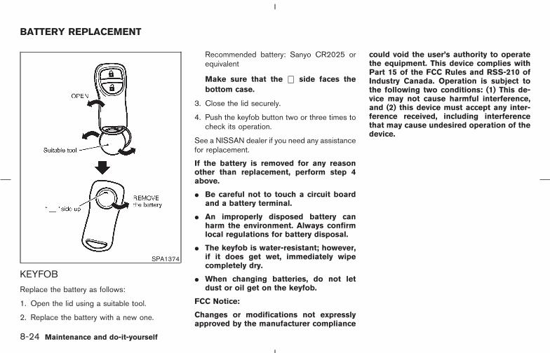
KEYFOB
Replace the battery as follows:
1. Open the lid using a suitable tool.
2. Replace the battery with a new one.
Recommended battery: Sanyo CR2025 orequivalent
Make sure that the ⊕ side faces thebottom case.
3. Close the lid securely.
4. Push the keyfob button two or three times tocheck its operation.
See a NISSAN dealer if you need any assistancefor replacement.
If the battery is removed for any reasonother than replacement, perform step 4above.
� Be careful not to touch a circuit boardand a battery terminal.
� An improperly disposed battery canharm the environment. Always confirmlocal regulations for battery disposal.
� The keyfob is water-resistant; however,if it does get wet, immediately wipecompletely dry.
� When changing batteries, do not letdust or oil get on the keyfob.
FCC Notice:
Changes or modifications not expresslyapproved by the manufacturer compliance
could void the user’s authority to operatethe equipment. This device complies withPart 15 of the FCC Rules and RSS-210 ofIndustry Canada. Operation is subject tothe following two conditions: (1) This de-vice may not cause harmful interference,and (2) this device must accept any inter-ference received, including interferencethat may cause undesired operation of thedevice.
SPA1374
BATTERY REPLACEMENT
8-24 Maintenance and do-it-yourself
� 04.8.3/Z50-D/V5.0 �

INTELLIGENT KEY
CAUTION
Be careful not to allow children to swal-low the battery and removed parts.
Replace the battery as follows:
1. Release the lock knob at the back of theintelligent key and remove the mechanicalkey.
2. Insert a flat-blade screwdriver �A wrappedwith a cloth into the slit �B of the corner andtwist it to separate the upper part from thelower part.
3. Replace the battery with a new one.
� Do not touch the internal circuit and electricterminals as it could cause a malfunction.
Recommended battery: CR2025 or equiva-lent
Make sure that the ⊕ side faces thebottom of the case.
4. Close the lid securely as illustrated �1 �2 .5. Push the buttons two or three times to check
its operation.
See a NISSAN dealer if you need any assistancefor replacement.
If the battery is removed for any reasonother than replacement, perform step 5above.
� Be careful not to touch the circuit boardand the battery terminal.
� An improperly disposed battery canharm the environment. Always confirmlocal regulations for battery disposal.
� When changing batteries, do not letdust or oil get on the Intelligent Key.
SDI1792
Maintenance and do-it-yourself 8-25
� 04.8.3/Z50-D/V5.0 �

1. Front turn signal light or front park light
2. Headlight (low-beam, high-beam)
3. Front park light or front turn signal light
4. Map light
5. Ceiling light
6. Rear personal light
7. Front fog light (if so equipped)/Daytime, run-ning light (for Canada)
8. Front side marker light
9. Step light
10. High-mounted stop light
Rear combination lights
11. Turn signal light (Rear combination lights)
12. Side marker light (Rear combination lights)
13. License plate lights
14. Back-up light
15. Luggage light
16. Stop/tail light (Rear combination lights)
SDI1497
LIGHTS
8-26 Maintenance and do-it-yourself
� 04.8.3/Z50-D/V5.0 �
HEADLIGHTS
ReplacingIf replacement is required, see a NISSAN dealer.
Xenon headlight bulb:
WARNING
HIGH VOLTAGE
When xenon headlights are on, theyproduce a high voltage. To prevent anelectric shock, never attempt to modifyor disassemble. Always have your xe-non headlights replaced at a NISSANdealer. For additional information, see“Headlight and turn signal switch” inthe “Instruments and controls” section.
Halogen headlight bulb:
The headlight is a semi-sealed beam type whichuses a replaceable headlight (halogen) bulb. Ifreplacement is required, see a NISSAN dealer.
CAUTION
� High pressure halogen gas is sealedinside the halogen bulb. The bulbmay break if the glass envelope isscratched or the bulb is dropped.
� When handling the bulb, do not touchthe glass envelope.
� Do not touch the bulb.
� Use the same number and wattage asoriginally installed:Bulb no. (Wattage)D2S - Xenon low/high-beamor
HB5 (65/55W) - Halogen low/high-beam
� Do not leave the bulb out of theheadlight reflector for a long periodof time as dust, moisture and smokemay enter the headlight body andaffect the performance of the head-light.
Maintenance and do-it-yourself 8-27
� 04.8.3/Z50-D/V5.0 �

EXTERIOR AND INTERIOR LIGHTS
Item Wattage (W) Bulb No.
Front turn signal* 21 T20
Front park light* 3.8 T10 C-2F
Front side marker light* 3.8 T10 C-2F
Front fog light (if so equipped)* 51 HB4
Rear combination light*
Turn signal 21 T20
Stop/Tail 21/5 T20
Side marker light 5 T10
Back-up* 16 T16
License plate light* 5 T10
High-mounted stop light* 2.4 LED
Ceiling light 8
Map light 8
Rear personal light* 8
Step light* 2.7 161
Luggage light 8 158
Vanity mirror light 2 —
*: See a NISSAN dealer for replacement.
Replacement proceduresAll other lights are either type A, B, C or D. Whenreplacing a bulb, first remove the lens and/orcover.
MDI0006
8-28 Maintenance and do-it-yourself
� 04.8.3/Z50-D/V5.0 �

TIRE PRESSURE
Low tire pressure warning system (ifso equipped)This vehicle is equipped with the low tire pres-sure warning system. It monitors tire pressure ofall tires except the spare. When the low tirepressure warning light is lit, one or more of yourtires is significantly underinflated. The systemalso displays pressure of all tires (except thespare tire) on the display screen by sending asignal from a sensor that is installed in eachwheel.
The low tire pressure warning system will acti-vate only when the vehicle is driven at speedsabove 20 MPH (32 km/h). Also, this system maynot detect a sudden drop in tire pressure (forexample a flat tire while driving).
For more details, refer to “Low tire pressurewarning light” in the “2. Instruments and con-trols” section, “Tire pressure information” in the“4. Display screen, heater, air conditioner andaudio systems” section, “Low tire pressurewarning system” in the “5. Starting and driving”section, and “Flat tire” in the “6. In case ofemergency” section.
Tire inflation pressureCheck the tire pressures (including the spare)often and always prior to long distance trips. The
SDI1498AMap light
SDI1499ACeiling light
SDI1500BLuggage light
SDI1506BVanity mirror light
WHEELS AND TIRES
Maintenance and do-it-yourself 8-29
� 04.8.3/Z50-D/V5.0 �

recommended tire pressure specifications areshown on the Tire and Loading Information labelunder the “Recommended Cold Tire InflationPressure” heading. The Tire and Loading Infor-mation label is affixed to the driver side centerpillar. Tire pressures should be checked regu-larly because:
� Most tires naturally lose air over time.
� Tires can lose air suddenly when driven overpotholes or other objects or if the vehiclestrikes a curb while parking.
The tire pressures should be checked when thetires are cold. The tires are considered COLDafter the vehicle has been parked for 3 or morehours, or driven less than 1 mile (1.6 km) atmoderate speeds.
Incorrect tire pressure, including under in-flation, may adversely affect tire life andvehicle handling.
WARNING
� Improperly inflated tires can fail sud-denly and cause an accident.
� The vehicle weight capacity is indi-cated on the Tire and Loading Infor-mation label. Do not load your ve-hicle beyond this capacity.Overloading your vehicle may resultin reduced tire life, unsafe operatingconditions due to premature tire fail-ure, or unfavorable handling charac-teristics and could also lead to aserious accident. Loading beyond thespecified capacity may also result infailure of other vehicle components.
� Before taking a long trip, or when-ever you heavily load your vehicle,use a tire pressure gauge to ensurethat the tire pressures are at thespecified level.
� Do not drive your vehicle over 85MPH (137 km/h) unless it is equippedwith high speed rated tires. Drivingfaster than 85 MPH (137 km/h) may
result in tire failure, loss of controland possible injury.
� For additional information regardingtires, refer to “Important Tire SafetyInformation” (US) or “Tire Safety In-formation” (Canada) in the WarrantyInformation Booklet.
8-30 Maintenance and do-it-yourself
� 04.8.3/Z50-D/V5.0 �
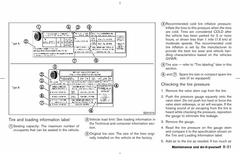
Tire and loading information label
�1 Seating capacity: The maximum number ofoccupants that can be seated in the vehicle.
�2 Vehicle load limit: See loading information inthe Technical and consumer information sec-tion.
�3 Original tire size: The size of the tires origi-nally installed on the vehicle at the factory.
�4 Recommended cold tire inflation pressure:Inflate the tires to this pressure when the tiresare cold. Tires are considered COLD afterthe vehicle has been parked for 3 or morehours, or driven less than 1 mile (1.6 km) atmoderate speeds. The recommended coldtire inflation is set by the manufacturer toprovide the best tire wear and vehicle han-dling characteristics based on the vehiclesGVWR.
�5 Tire size — refer to “Tire labeling” later in thissection.
�6 and �7 Spare tire size or compact spare tiresize (if so equipped)
Checking the tire pressure1. Remove the valve stem cap from the tire.
2. Push the pressure gauge squarely onto thevalve stem. Do not push too hard or force thevalve stem sideways, or air will escape. If thehissing sound of air escaping from the tire isheard while checking the pressure, repositionthe gauge to eliminate this leakage.
3. Remove the gauge.
4. Read the tire pressure on the gauge stemand compare it to the specification shown onthe Tire and Loading Information label.
5. Add air to the tire as needed. If too much air
SDI1574
Maintenance and do-it-yourself 8-31
� 04.8.3/Z50-D/V5.0 �
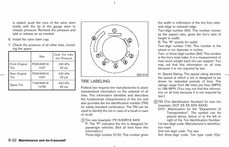
is added, push the core of the valve stembriefly with the tip of the gauge stem torelease pressure. Recheck the pressure andadd or release air as needed.
6. Install the valve stem cap.
7. Check the pressure of all other tires, includ-ing the spare.
SizeCold Tire Infla-tion Pressure
Front OriginalTire
P235/65R18104T
230 kPa33 psi
Rear OriginalTire
P235/65R18104T
230 kPa33 psi
Spare TireT165/90D18
107M420 kPa60 psi
TIRE LABELING
Federal law requires tire manufacturers to placestandardized information on the sidewall of alltires. This information identifies and describesthe fundamental characteristics of the tire andalso provides the tire identification number (TIN)for safety standard certification. The TIN can beused to identify the tire in case of a recall in caseof recall.
�1 Tire size (example: P215/60R16 94H)P: The “P” indicates the tire is designed forpassenger vehicles. (Not all tires have thisinformation.)Three-digit number (215): This number gives
the width in millimeters of the tire from side-wall edge to sidewall edge.Two-digit number (60): This number, knownas the aspect ratio, gives the tire’s ratio ofheight to width.R: The “R” stands for radial.Two-digit number (16): This number is thewheel or rim diameter in inches.Two- or three-digit number (94): This numberis the tire’s load index. It is a measurement ofhow much weight each tire can support. Youmay not find this information on all tiresbecause it is not required by law.
H: Speed Rating. The speed rating denotesthe speed at which a tire is designed to bedriven for extended periods of time. Theratings range from 98 miles per hour (MPH)to 186 MPH. (You may not find this informa-tion on all tires because it is not required bylaw.)
�2 TIN (Tire Identification Number) for new tire(example: DOT XX XX XXX XXXX)DOT: Abbreviation for the “Department of
Transportation”. The symbol can beplaced above, below or to the left orright of the Tire Identification Number.
1st two-digit code: Manufacturer’s identifica-tion mark2nd two-digit code: Tire size3rd three-digit code: Tire type code (Op-
SDI1575
8-32 Maintenance and do-it-yourself
� 04.8.3/Z50-D/V5.0 �

tional)4th four-digit code: Date of ManufactureFour numbers represent the week and yearthe tire was built. For example, the numbers3103 means the 31st week of 2003.
�3 Tire ply composition and materialThe number of layers or plies of rubber-coated fabric in the tire.Tire manufacturers also must indicate thematerials in the tire, which include steel,nylon, polyester, and others.
�4 Maximum permissible inflation pressureThis number is the greatest amount of airpressure that should be put in the tire. Do notexceed the maximum permissible inflationpressure.
�5 Maximum load ratingThis number indicates the maximum load inkilograms and pounds that can be carried bythe tire. When replacing the tires on thevehicle, always use a tire that has the sameload rating as the factory installed tire.
�6 Term of “tubeless” or “tube type”Indicates that the tire requires an inner tube(“tube type”) or not (“tubeless”).
�7 The word “radial”The word “radial” is shown, if the tire hasradial structure.
�8 Manufacturer or Brand nameManufacturer or Brand name is shown.
Other tire-related terminology
In addition to the many terms that are definedthroughout this section, Intended OutboardSidewall is (1) the sidewall that contains awhitewall, bears while lettering or bears manu-facturer, brand and/or model name molding thatis higher or deeper than the same molding on theother sidewall of the tire, or (2) the outwardracing sidewall of an asymmetrical tire that has aparticular side that must always face outwardwhen mounted on a vehicle.
TYPES OF TIRES
CAUTION
� When changing or replacing tires, besure all four tires are of the sametype (for example, summer, all sea-son or snow) and construction. ANISSAN dealer may be able to helpyou with information about tire type,size, speed rating and availability.
� Replacement tires may have a lowerspeed rating than the factory
equipped tires, and may not matchthe potential maximum vehiclespeed. Never exceed the maximumspeed rating of the tire.
� For additional information regardingtires, refer to “Important Tire SafetyInformation” (US) or “Tire Safety In-formation” (Canada) in the WarrantyInformation Booklet.
All season tires
NISSAN specifies all season tires on somemodels to provide good performance for use allyear round, including snowy and icy road condi-tions. All season tires are identified by ALLSEASON and/or M&S (Mud and Snow) on thetire sidewall. Snow tires have better snow trac-tion than all season tires and may be moreappropriate in some areas.
Summer tires
NISSAN specifies summer tires on some modelsto provide superior performance on dry roads.Summer tire performance is substantially re-duced in snow and ice. Summer tires do nothave the tire traction rating M&S (Mud andSnow) on the tire sidewall.
Maintenance and do-it-yourself 8-33
� 04.8.3/Z50-D/V5.0 �

If you plan to operate your vehicle in snowy or icyconditions, NISSAN recommends the use ofsnow tires or all season tires on all four wheels.
Snow tiresIf snow tires are needed, it is necessary to selecttires equivalent in size and load rating to theoriginal equipment tires. If you do not, it canadversely affect the safety and handling of yourvehicle.
Generally, snow tires will have lower speedratings than factory equipped tires and may notmatch the potential maximum vehicle speed.Never exceed the maximum speed rating of thetire.
If you operate your vehicle in snowy or icyconditions, NISSAN recommends the use ofsnow or all season tires on all four wheels.
For additional traction on icy roads, studded tiresmay be used. However, some provinces andstates prohibit their use. Check local, state andprovincial laws before installing studded tires.Skid and traction capabilities of studded snowtires, on wet or dry surfaces, may be poorer thanthat of non-studded snow tires.
All wheel drive models
CAUTION
Always use tires of the same type, size,brand, construction (bias, bias-belted orradial), and tread pattern on all fourwheels. Failure to do so may result in acircumference difference between tireson the front and rear axles which willcause excessive tire wear and may dam-age the transmission, transfer case anddifferential gears.
If excessive tire wear is found, it is recommendedthat all four tires be replaced with tires of thesame size, brand, construction and tread pat-tern. The tire pressure and wheel alignmentshould also be checked and corrected as nec-essary. Contact a NISSAN dealer.
Tire chains must be installed only on thefront wheels and not on the rear wheels.
Do not drive with tire chains on paved roadswhich are clear of snow. Driving with chains insuch conditions can cause damage to the vari-ous mechanisms of the vehicle due to someoverstress.
TIRE CHAINS
Use of tire chains may be prohibited accordingto location. Check the local laws before installingtire chains. When installing tire chains, makesure they are of proper size for the tires on yourvehicle and are installed according to the chainmanufacturer’s suggestions. Use only SAEclass S chains. Class “S” chains are used onvehicles with restricted tire to vehicle clearance.Vehicles that can use Class “S” chains aredesigned to meet the SAE standard minimumclearances between the tire and the closestvehicle suspension or body component requiredto accommodate the use of a winter tractiondevice (tire chains or cables). The minimumclearances are determined using the factoryequipped tire size. Other types may damageyour vehicle. Use chain tensioners when recom-mended by the tire chain manufacturer to ensurea tight fit. Loose end links of the tire chain mustbe secured or removed to prevent the possibilityof whipping action damage to the fenders orundercarriage. If possible, avoid fully loadingyour vehicle when using tire chains. In addition,drive at a reduced speed. Otherwise, your ve-hicle may be damaged and/or vehicle handlingand performance may be adversely affected.
� Never install tire chains on a TEMPO-RARY USE ONLY type spare tire.
8-34 Maintenance and do-it-yourself
� 04.8.3/Z50-D/V5.0 �
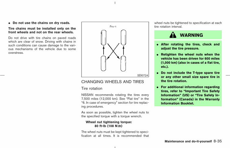
� Do not use the chains on dry roads.
Tire chains must be installed only on thefront wheels and not on the rear wheels.
Do not drive with tire chains on paved roadswhich are clear of snow. Driving with chains insuch conditions can cause damage to the vari-ous mechanisms of the vehicle due to someoverstress.
CHANGING WHEELS AND TIRES
Tire rotation
NISSAN recommends rotating the tires every7,500 miles (12,000 km). See “Flat tire” in the“6. In case of emergency” section for tire replac-ing procedures.
As soon as possible, tighten the wheel nuts tothe specified torque with a torque wrench.
Wheel nut tightening torque:80 ft-lb (108 N⋅m)
The wheel nuts must be kept tightened to speci-fication at all times. It is recommended that
wheel nuts be tightened to specification at eachtire rotation interval.
WARNING
� After rotating the tires, check andadjust the tire pressure.
� Retighten the wheel nuts when thevehicle has been driven for 600 miles(1,000 km) (also in cases of a flat tire,etc.).
� Do not include the T-type spare tireor any other small size spare tire inthe tire rotation.
� For additional information regardingtires, refer to “Important Tire SafetyInformation” (US) or “Tire Safety In-formation” (Canada) in the WarrantyInformation Booklet.
SDI0724
Maintenance and do-it-yourself 8-35
� 04.8.3/Z50-D/V5.0 �

1. Wear indicator2. Wear indicator location mark
Tire wear and damage
WARNING
� Tires should be periodically in-spected for wear, cracking, bulging orobjects caught in the tread. If exces-sive wear, cracks, bulging or deepcuts are found, the tire should bereplaced.
� The original tires have built-in treadwear indicators. When the wear indi-cators are visible, the tire(s) shouldbe replaced.
� Improper service of the spare tiremay result in serious personal injury.If it is necessary to repair the sparetire, contact a NISSAN dealer.
� For additional information regardingtires, refer to “Important Tire SafetyInformation” (US) or “Tire Safety In-formation” (Canada) in the WarrantyInformation Booklet.
Replacing wheels and tiresWhen replacing a tire, use the same size, treaddesign, speed rating and load carrying capacityas originally equipped. See “Specifications” inthe “9. Technical and consumer information”section for recommended types and sizes oftires and wheels.
WARNING
� The use of tires other than thoserecommended or the mixed use oftires of different brands, construction(bias, bias-belted or radial), or treadpatterns can adversely affect the ride,braking, handling, ground clearance,body-to-tire clearance, tire chainclearance, speedometer calibration,headlight aim and bumper height.Some of these effects may lead toaccidents and could result in seriouspersonal injury.
� If the wheels are changed for anyreason, always replace with wheelswhich have the same off-set dimen-sion. Wheels of a different off-setcould cause premature tire wear, de-grade vehicle handling characteris-tics and/or interference with thebrake discs/drums. Such interfer-ence can lead to decreased brakingefficiency and/or early brakepad/shoe wear. Refer to “Tire and
SDI1663
8-36 Maintenance and do-it-yourself
� 04.8.3/Z50-D/V5.0 �

wheels” in the “9. Technical and con-sumer information” section of thismanual for wheel offset dimensions.
� When a spare tire is mounted or awheel is replaced, the pressure ofthat tire will not be indicated and notbe monitored by the low tire pressurewarning system. Contact a NISSANdealer as soon as possible for tirereplacement and/or system reset-ting. (For models with the low tirepressure warning system)
� Do not install a deformed wheel ortire even if it has been repaired. Suchwheels or tires could have structuraldamage and could fail without warn-ing.
� The use of retread tires is not recom-mended.
� For additional information regardingtires, refer to “Important Tire SafetyInformation” (US) or “Tire Safety In-formation” (Canada) in the WarrantyInformation Booklet.
Wheel balance
Unbalanced wheels may affect vehicle handlingand tire life. Even with regular use, wheels canget out of balance. Therefore, they should bebalanced as required.
Wheel balance service should be performedwith the wheels off the vehicle. Spin balancingthe front wheels on the vehicle could lead tomechanical damage.
For additional information regarding tires, refer to“Important Tire Safety Information” (US) or “TireSafety Information” (Canada) in the WarrantyInformation booklet.
Care of wheels� Wash the wheels when washing the vehicle
to maintain their appearance.
� Clean the inner side of the wheels when thewheel is changed or the underside of thevehicle is washed.
� Do not use abrasive cleaners when washingthe wheels.
� Inspect wheel rims regularly for dents orcorrosion. Such damage may cause loss ofpressure or poor seal at the tire bead.
� NISSAN recommends waxing the road wheelsidewalls to protect against road salt in areas
where it is used during winter.
Spare tire (TEMPORARY USE ONLY(T-type) spare tire)Observe the following precautions if the TEM-PORARY USE ONLY spare tire must be used.Otherwise, your vehicle could be damaged orinvolved in an accident.
WARNING
� The spare tire should be used foremergency use only. It should be re-placed with the standard tire at thefirst opportunity to avoid possibletire or differential damage.
� Drive carefully while the TEMPO-RARY USE ONLY spare tire is in-stalled.
Avoid sharp turns and abrupt brakingwhile driving.
� Periodically check spare tire inflationpressure. Always keep the pressureof the TEMPORARY USE ONLY sparetire at 60 psi (420 kPa, 4.2 bar).
� With the TEMPORARY USE ONLY
Maintenance and do-it-yourself 8-37
� 04.8.3/Z50-D/V5.0 �
spare tire installed do not drive thevehicle at speeds faster than 50 MPH(80 km/h).
� When driving on roads covered withsnow or ice, the TEMPORARY USEONLY spare tire should be used onthe rear wheel and the original tireused on the front wheels (drivewheels). Use tire chains only on thefront (original) tires.
� Tire tread of the TEMPORARY USEONLY spare tire will wear at a fasterrate than the standard tire. Replacethe spare tire as soon as the treadwear indicators appear.
� Do not use the spare tire on othervehicles.
� Do not use more than one spare tireat the same time.
� Do not tow a trailer when the TEM-PORARY USE ONLY spare tire is in-stalled.
CAUTION
� Do not use tire chains on a TEMPO-RARY USE ONLY spare tire. Tirechains will not fit properly and maycause damage to the vehicle.
� Because the TEMPORARY USEONLY spare tire is smaller than theoriginal tire, ground clearance is re-duced. To avoid damage to the ve-hicle, do not drive over obstacles.Also, do not drive the vehicle throughan automatic car wash since it mayget caught.
8-38 Maintenance and do-it-yourself
� 04.8.3/Z50-D/V5.0 �

MEMO
Maintenance and do-it-yourself 8-39
� 04.8.3/Z50-D/V5.0 �

MEMO
8-40 Maintenance and do-it-yourself
� 04.8.3/Z50-D/V5.0 �

9 Technical and consumer information
Capacities and recommended fuel/lubricants................ 9-2Fuel recommendation...................................................... 9-3Engine oil and oil filter recommendation.................... 9-5Recommended SAE viscosity number ....................... 9-6Air conditioning system refrigerant and lubricantrecommendations............................................................. 9-6
Specifications.......................................................................... 9-8Engine ................................................................................. 9-8Wheels and tires .............................................................. 9-9Dimensions and weights ................................................ 9-9
When traveling or registering your vehicle in anothercountry.................................................................................... 9-10Vehicle identification........................................................... 9-10
Vehicle identification number (VIN) plate ................ 9-10Vehicle identification number (Chassis number) ... 9-10Engine serial number .................................................... 9-11F.M.V.S.S. certification label ....................................... 9-11Emission control information label ............................ 9-11Tire and loading information label ............................. 9-12Air conditioner specification label ............................. 9-12
Installing front license plate .............................................. 9-13Vehicle loading information............................................... 9-14
Terms ................................................................................ 9-14Vehicle load capacity.................................................... 9-15Loading tips .................................................................... 9-16Payload weight capacity .............................................. 9-16Measurement of weights ............................................. 9-16
Towing a trailer .................................................................... 9-17Maximum load limits...................................................... 9-18Towing load/specification chart ................................. 9-19Towing safety.................................................................. 9-20
Uniform tire quality grading............................................... 9-23Emission control system warranty................................... 9-24Reporting safety defects (US only) ................................ 9-24Readiness for inspection/maintenance (I/M) test(US only)................................................................................ 9-24Event data recorders ......................................................... 9-25Owner’s Manual/Service Manual order information ... 9-26
In the event of a collision ............................................ 9-26
� 04.8.3/Z50-D/V5.0 �
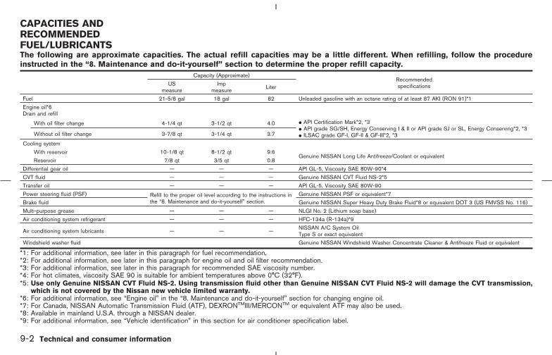
The following are approximate capacities. The actual refill capacities may be a little different. When refilling, follow the procedureinstructed in the “8. Maintenance and do-it-yourself” section to determine the proper refill capacity.
Capacity (Approximate)RecommendedspecificationsUS
measureImp
measure Liter
Fuel 21-5/8 gal 18 gal 82 Unleaded gasoline with an octane rating of at least 87 AKI (RON 91)*1
Engine oil*6Drain and refill
With oil filter change 4-1/4 qt 3-1/2 qt 4.0 � API Certification Mark*2, *3� API grade SG/SH, Energy Conserving I & II or API grade SJ or SL, Energy Conserving*2, *3� ILSAC grade GF-I, GF-II & GF-III*2, *3Without oil filter change 3-7/8 qt 3-1/4 qt 3.7
Cooling system
With reservoir 10-1/8 qt 8-1/2 qt 9.6Genuine NISSAN Long Life Antifreeze/Coolant or equivalent
Reservoir 7/8 qt 3/5 qt 0.8
Differential gear oil — — — API GL-5, Viscosity SAE 80W-90*4
CVT fluid — — — Genuine NISSAN CVT Fluid NS-2*5
Transfer oil — — — API GL-5, Viscosity SAE 80W-90
Power steering fluid (PSF) Refill to the proper oil level according to the instructions inthe “8. Maintenance and do-it-yourself” section.
Genuine NISSAN PSF or equivalent*7
Brake fluid Genuine NISSAN Super Heavy Duty Brake Fluid*8 or equivalent DOT 3 (US FMVSS No. 116)
Multi-purpose grease — — — NLGI No. 2 (Lithium soap base)
Air conditioning system refrigerant — — — HFC-134a (R-134a)*9
Air conditioning system lubricants — — — NISSAN A/C System OilType S or exact equivalent
Windshield washer fluid Genuine NISSAN Windshield Washer Concentrate Cleaner & Antifreeze Fluid or equivalent
*1: For additional information, see later in this paragraph for fuel recommendation.*2: For additional information, see later in this paragraph for engine oil and oil filter recommendation.*3: For additional information, see later in this paragraph for recommended SAE viscosity number.*4: For hot climates, viscosity SAE 90 is suitable for ambient temperatures above 0°C (32°F).*5: Use only Genuine NISSAN CVT Fluid NS-2. Using transmission fluid other than Genuine NISSAN CVT Fluid NS-2 will damage the CVT transmission,
which is not covered by the Nissan new vehicle limited warranty.*6: For additional information, see “Engine oil” in the “8. Maintenance and do-it-yourself” section for changing engine oil.*7: For Canada, NISSAN Automatic Transmission Fluid (ATF), DEXRONTMIII/MERCONTM or equivalent ATF may also be used.*8: Available in mainland U.S.A. through a NISSAN dealer.*9: For additional information, see “Vehicle identification” in this section for air conditioner specification label.
CAPACITIES ANDRECOMMENDEDFUEL/LUBRICANTS
9-2 Technical and consumer information
� 04.8.3/Z50-D/V5.0 �
FUEL RECOMMENDATION
Use unleaded regular gasoline with an oc-tane rating of at least 87 AKI (Anti-KnockIndex) number (Research octane number91).
For improved vehicle performance,NISSAN recommends the use of unleadedpremium gasoline with an octane rating ofat least 91 AKI number (Research octanenumber 96).
CAUTION
Using a fuel other than that specifiedcould adversely affect the emission con-trol system, and may also affect thewarranty coverage.
Under no circumstances should aleaded gasoline be used, because thiswill damage the three-way catalyst.
Gasoline specifications
NISSAN recommends using gasoline that meetsthe World-Wide Fuel Charter (WWFC) specifi-cations where it is available. Many of the auto-mobile manufacturers developed this specifica-
tion to improve the emission control system andvehicle performance. Ask your service stationmanager if the gasoline meets the WWFCspecifications.
Reformulated gasoline
Some fuel suppliers are now producing reformu-lated gasolines. These gasolines are speciallydesigned to reduce vehicle emissions. NISSANsupports efforts towards cleaner air and sug-gests that you use reformulated gasoline whenavailable.
Gasoline containing oxygenates
Some fuel suppliers sell gasoline containingoxygenates such as ethanol, MTBE and metha-nol with or without advertising their presence.NISSAN does not recommend the use of fuels ofwhich the oxygenate content and the fuel com-patibility for a NISSAN cannot be readily deter-mined. If in doubt, ask your service stationmanager.
If you use oxygenate-blend gasoline, please takethe following precautions as the usage of suchfuels may cause vehicle performance problemsand/or fuel system damage.
� The fuel should be unleaded and havean octane rating no lower than thatrecommended for unleaded gasoline.
� If an oxygenate-blend, excepting amethanol blend, is used, it should con-tain no more than 10% oxygenate.(MTBE may, however, be added up to15%.)
� If a methanol blend is used, it shouldcontain no more than 5% methanol (me-thyl alcohol, wood alcohol). It shouldalso contain a suitable amount of ap-propriate cosolvents and corrosion in-hibitors. If not properly formulated withappropriate cosolvents and corrosioninhibitors, such methanol blends maycause fuel system damage and/or ve-hicle performance problems. At thistime, sufficient data is not available toensure that all methanol blends aresuitable for use in NISSAN vehicles.
If any undesirable driveability problems such asengine stalling and hard hot starting are experi-enced after using oxygenate-blend fuels, imme-diately change to a non-oxygenate fuel or a fuelwith a low blend of MTBE.
Take care not to spill gasoline during refu-eling. Gasoline containing oxygenates cancause paint damage.
Aftermarket fuel additivesNISSAN does not recommend the use of any
Technical and consumer information 9-3
� 04.8.3/Z50-D/V5.0 �
aftermarket fuel additives (for example, fuel in-jector cleaner, octane booster, intake valve de-posit removers, etc.) which are sold commer-cially. Many of these additives intended for gum,varnish or deposit removal may contain activesolvent or similar ingredients that can be harmfulto the fuel system and engine.
Octane rating tipsUsing unleaded gasoline with an octanerating lower than recommended can causepersistent, heavy spark knock. (Sparkknock is a metallic rapping noise.) If se-vere, this can lead to engine damage. If youdetect a persistent heavy spark knock evenwhen using gasoline of the stated octanerating, or if you hear steady spark knockwhile holding a steady speed on levelroads, have your dealer correct the condi-tion. Failure to correct the condition ismisuse of the vehicle, for which NISSAN isnot responsible.
Incorrect ignition timing will result in knocking,after-run or overheating. This in turn may causeexcessive fuel consumption or damage to theengine. If any of the above symptoms are en-countered, have your vehicle checked at aNISSAN dealer or other competent service fa-cility.
However, now and then you may notice
light spark knock for a short time whileaccelerating or driving up hills. This is nocause for concern, because you get thegreatest fuel benefit when there is lightspark knock for a short time under heavyengine load.
9-4 Technical and consumer information
� 04.8.3/Z50-D/V5.0 �
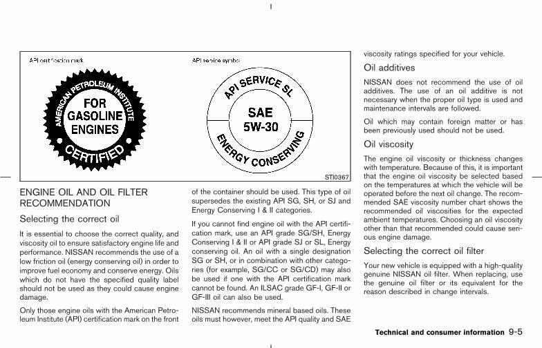
ENGINE OIL AND OIL FILTERRECOMMENDATION
Selecting the correct oil
It is essential to choose the correct quality, andviscosity oil to ensure satisfactory engine life andperformance. NISSAN recommends the use of alow friction oil (energy conserving oil) in order toimprove fuel economy and conserve energy. Oilswhich do not have the specified quality labelshould not be used as they could cause enginedamage.
Only those engine oils with the American Petro-leum Institute (API) certification mark on the front
of the container should be used. This type of oilsupersedes the existing API SG, SH, or SJ andEnergy Conserving I & II categories.
If you cannot find engine oil with the API certifi-cation mark, use an API grade SG/SH, EnergyConserving I & II or API grade SJ or SL, Energyconserving oil. An oil with a single designationSG or SH, or in combination with other catego-ries (for example, SG/CC or SG/CD) may alsobe used if one with the API certification markcannot be found. An ILSAC grade GF-I, GF-II orGF-III oil can also be used.
NISSAN recommends mineral based oils. Theseoils must however, meet the API quality and SAE
viscosity ratings specified for your vehicle.
Oil additivesNISSAN does not recommend the use of oiladditives. The use of an oil additive is notnecessary when the proper oil type is used andmaintenance intervals are followed.
Oil which may contain foreign matter or hasbeen previously used should not be used.
Oil viscosityThe engine oil viscosity or thickness changeswith temperature. Because of this, it is importantthat the engine oil viscosity be selected basedon the temperatures at which the vehicle will beoperated before the next oil change. The recom-mended SAE viscosity number chart shows therecommended oil viscosities for the expectedambient temperatures. Choosing an oil viscosityother than that recommended could cause seri-ous engine damage.
Selecting the correct oil filterYour new vehicle is equipped with a high-qualitygenuine NISSAN oil filter. When replacing, usethe genuine oil filter or its equivalent for thereason described in change intervals.
STI0367
Technical and consumer information 9-5
� 04.8.3/Z50-D/V5.0 �

Change intervalsThe oil and oil filter change intervals for yourengine are based on the use of the specifiedquality oils and filters. Oil and filter other than thespecified quality, or oil and filter change intervalslonger than recommended could reduce enginelife. Damage to engines caused by impropermaintenance or use of incorrect oil and filterquality and/or viscosity is not covered by thenew NISSAN vehicle warranties.
Your engine was filled with a high quality engineoil when it was built. You do not have to changethe oil before the first recommended changeinterval. Oil and filter change intervals dependupon how you use your vehicle. Operation underthe following conditions may require more fre-quent oil and filter changes.
� repeated short distance driving at cold out-side temperatures,
� driving in dusty conditions,
� extensive idling,
� towing a trailer,
� stop and go “rush hour” traffic,
� aggressive driving.
RECOMMENDED SAE VISCOSITYNUMBER
SAE 5W-30 viscosity oil is preferred for allambient temperatures. SAE 10W-30,10W-40 viscosity oil may be used if theambient temperature is above 0°F (−18°C).
AIR CONDITIONING SYSTEMREFRIGERANT AND LUBRICANTRECOMMENDATIONS
The air conditioning system in this NISSANvehicle must be charged with the refriger-ant HFC-134a (R-134a) and the lubricant,NISSAN A/C System Oil Type S or theexact equivalents.
CAUTION
The use of any other refrigerant or lubri-cant will cause severe damage to the airconditioning system and will require thereplacement of all air conditioner sys-tem components.
The refrigerant HFC-134a (R-134a) in yourNISSAN vehicle will not harm the earth’s ozonelayer. Although this refrigerant does not affectthe earth’s atmosphere, certain governmentalregulations require the recovery and recycling ofany refrigerant during automotive air condition-ing system service. A NISSAN dealer has thetrained technicians and equipment needed torecover and recycle your air conditioning systemrefrigerant.
TI1028-C
9-6 Technical and consumer information
� 04.8.3/Z50-D/V5.0 �
Contact a NISSAN dealer when servicing yourair conditioning system.
Technical and consumer information 9-7
� 04.8.3/Z50-D/V5.0 �

ENGINE
Model VQ35DE
Type Gasoline, 4-cycle
Cylinder arrangement 6-cylinder, V-slanted at 60°
Bore x Stroke in (mm) 3.760 x 3.205 (95.5 x 81.4)
Displacement cu in (cm3) 213.45 (3,498)
Firing order 1-2-3-4-5-6*
Idle speed rpmSee the emission control label on theunderside of the hood.
Ignition timing (B.T.D.C.) degree/rpm
CO percentage at idle speed [No air] %
Spark plugStandard PLFR5A-11
Service option PLFR4A-11 (Hot), PLFR6A-11 (Cold)
Spark plug gap (Normal) in (mm) 0.043 (1.1)
Camshaft operation Timing chain
The spark ignition system of this vehiclemeets all requirements of the CanadianInterference-Causing Equipment Regula-tions.
TI1009-A
SPECIFICATIONS
9-8 Technical and consumer information
� 04.8.3/Z50-D/V5.0 �

WHEELS AND TIRES
Road wheelType Size Offset in (mm)
Aluminum 18 x 7-1/2JJ 1.38 (35)
Tire
Conventional P235/65R18 104T
SpareT165/90D18 107MConventional*
Pressure (cold)Conventional 33 PSI (230 kPa)
Spare (T-type) 60 PSI (420 kPa)
*: For Canada
DIMENSIONS AND WEIGHTS
Overall length in (mm) 187.6 (4,767)
Overall width in (mm) 74.0 (1,880)
Overall height without roof rack rail in (mm) 66.5 (1,689)
Overall height with roof rack rail in (mm) 67.3 (1,709)
Front tread in (mm) 64.2 (1,630)
Rear tread in (mm) 64.2 (1,630)
Wheelbase in (mm) 111.2 (2,825)
Gross vehicle weight rating lb (kg)
See the F.M.V.S.S. certifica-tion label on the driver’s sidelock pillar.
Gross axle weight rating
Front lb (kg)
Rear lb (kg)
Technical and consumer information 9-9
� 04.8.3/Z50-D/V5.0 �

When planning to travel in another country,you should first find out if the fuel available issuitable for your vehicle’s engine.
Using fuel with too low an octane rating maycause engine damage. All gasoline vehiclesmust be operated with unleaded engine gaso-line. Therefore, avoid taking your vehicle to areaswhere appropriate fuel is not available.
When transferring the registration of yourvehicle to another country, state, provinceor district, it may be necessary to modify thevehicle to meet local laws and regulations.
The laws and regulations for motor vehicle emis-sion control and safety standards vary accordingto the country, state, province or district; there-fore, vehicle specifications may differ.
When any vehicle is to be taken into an-other country, state, province or districtand registered, its modifications, transpor-tation, and registration are the responsibil-ity of the user. NISSAN is not responsiblefor any inconvenience that may result.
VEHICLE IDENTIFICATION NUMBER(VIN) PLATEThe vehicle identification number plate is at-tached as shown. This number is the identifica-tion for your vehicle and is used in the vehicleregistration.
VEHICLE IDENTIFICATION NUMBER(Chassis number)The number is stamped under the passenger’sseat as shown.
STI0334 STI0374
WHEN TRAVELING ORREGISTERING YOUR VEHICLE INANOTHER COUNTRY
VEHICLE IDENTIFICATION
9-10 Technical and consumer information
� 04.8.3/Z50-D/V5.0 �
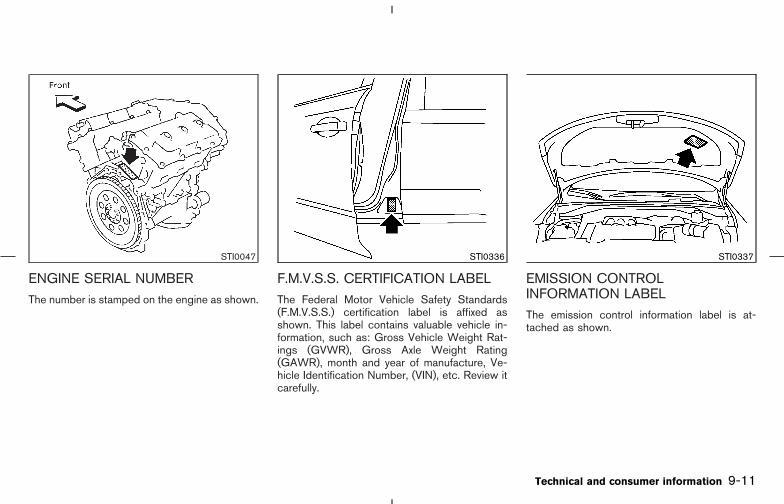
ENGINE SERIAL NUMBERThe number is stamped on the engine as shown.
F.M.V.S.S. CERTIFICATION LABELThe Federal Motor Vehicle Safety Standards(F.M.V.S.S.) certification label is affixed asshown. This label contains valuable vehicle in-formation, such as: Gross Vehicle Weight Rat-ings (GVWR), Gross Axle Weight Rating(GAWR), month and year of manufacture, Ve-hicle Identification Number, (VIN), etc. Review itcarefully.
EMISSION CONTROLINFORMATION LABELThe emission control information label is at-tached as shown.
STI0047 STI0336 STI0337
Technical and consumer information 9-11
� 04.8.3/Z50-D/V5.0 �
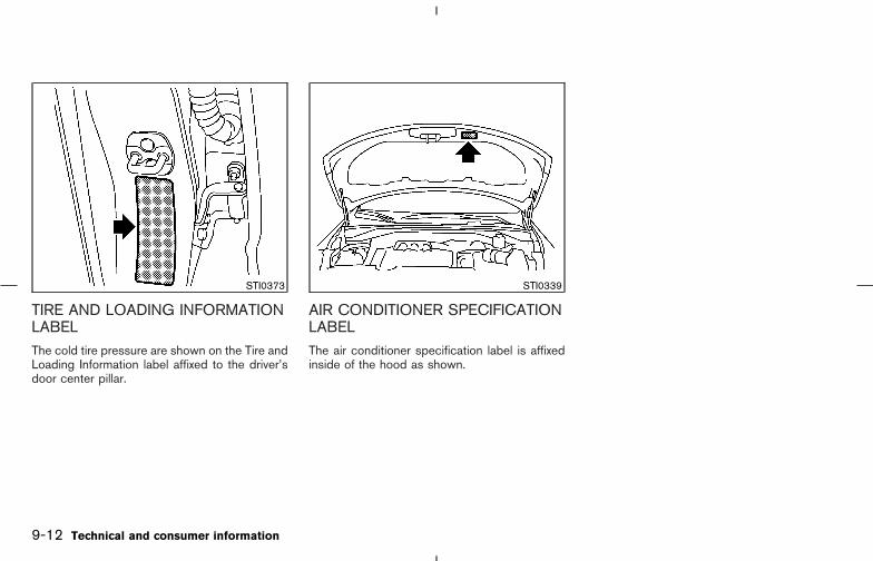
TIRE AND LOADING INFORMATIONLABELThe cold tire pressure are shown on the Tire andLoading Information label affixed to the driver’sdoor center pillar.
AIR CONDITIONER SPECIFICATIONLABELThe air conditioner specification label is affixedinside of the hood as shown.
STI0373 STI0339
9-12 Technical and consumer information
� 04.8.3/Z50-D/V5.0 �
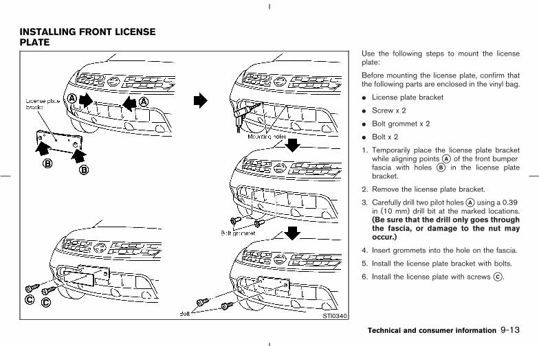
Use the following steps to mount the licenseplate:
Before mounting the license plate, confirm thatthe following parts are enclosed in the vinyl bag.
� License plate bracket
� Screw x 2
� Bolt grommet x 2
� Bolt x 2
1. Temporarily place the license plate bracketwhile aligning points �A of the front bumperfascia with holes �B in the license platebracket.
2. Remove the license plate bracket.
3. Carefully drill two pilot holes �A using a 0.39in (10 mm) drill bit at the marked locations.(Be sure that the drill only goes throughthe fascia, or damage to the nut mayoccur.)
4. Insert grommets into the hole on the fascia.
5. Install the license plate bracket with bolts.
6. Install the license plate with screws �C .
STI0340
INSTALLING FRONT LICENSEPLATE
Technical and consumer information 9-13
� 04.8.3/Z50-D/V5.0 �

WARNING
� It is extremely dangerous to ride in acargo area inside of a vehicle. In acollision, people riding in these areasare more likely to be seriously in-jured or killed.
� Do not allow people to ride in anyarea of your vehicle that is notequipped with seats and seat belts.
� Be sure everyone in your vehicle is ina seat and using a seat belt properly.
TERMS
It is important to familiarize yourself with thefollowing terms before loading your vehicle:
� Curb Weight (actual weight of your vehicle) -vehicle weight including: standard and op-tional equipment, fluids, emergency tools,and spare tire assembly. This weight doesnot include passengers and cargo.
� GVW (Gross Vehicle Weight) - curb weightplus the combined weight of passengers andcargo.
� GVWR (Gross Vehicle Weight Rating) -maximum total combined weight of the un-loaded vehicle, passengers, luggage, hitch,trailer tongue load and any other optionalequipment. This information is located on theF.M.V.S.S. label.
� GAWR (Gross Axle Weight Rating) - maxi-mum weight (load) limit specified for the frontor rear axle. This information is located on theF.M.V.S.S. label.
� GCWR (Gross Combined Weight Rating) -The maximum total weight rating of the ve-hicle, passengers, cargo, and trailer.
� Vehicle Capacity Weight, Load limit, Totalload capacity - maximum total weight limitspecified of the load (passengers and cargo)for the vehicle. This is the maximum com-bined weight of occupants and cargo thatcan be loaded into the vehicle. If the vehicle isused to tow a trailer, the trailer tongue weightmust be included as part of the cargo load.This information is located on the Tire andLoading Information label.
� Cargo capacity - permissible weight of cargo,the subtracted weight of occupants from theload limit.
VEHICLE LOADINGINFORMATION
9-14 Technical and consumer information
� 04.8.3/Z50-D/V5.0 �
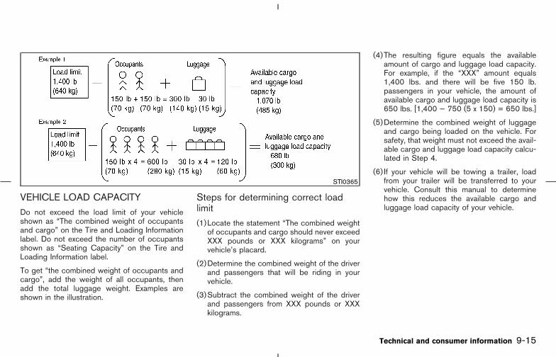
VEHICLE LOAD CAPACITYDo not exceed the load limit of your vehicleshown as “The combined weight of occupantsand cargo” on the Tire and Loading Informationlabel. Do not exceed the number of occupantsshown as “Seating Capacity” on the Tire andLoading Information label.
To get “the combined weight of occupants andcargo”, add the weight of all occupants, thenadd the total luggage weight. Examples areshown in the illustration.
Steps for determining correct loadlimit(1)Locate the statement “The combined weight
of occupants and cargo should never exceedXXX pounds or XXX kilograms” on yourvehicle’s placard.
(2)Determine the combined weight of the driverand passengers that will be riding in yourvehicle.
(3)Subtract the combined weight of the driverand passengers from XXX pounds or XXXkilograms.
(4)The resulting figure equals the availableamount of cargo and luggage load capacity.For example, if the “XXX” amount equals1,400 lbs. and there will be five 150 lb.passengers in your vehicle, the amount ofavailable cargo and luggage load capacity is650 lbs. [1,400 − 750 (5 x 150) = 650 lbs.]
(5)Determine the combined weight of luggageand cargo being loaded on the vehicle. Forsafety, that weight must not exceed the avail-able cargo and luggage load capacity calcu-lated in Step 4.
(6) If your vehicle will be towing a trailer, loadfrom your trailer will be transferred to yourvehicle. Consult this manual to determinehow this reduces the available cargo andluggage load capacity of your vehicle.
STI0365
Technical and consumer information 9-15
� 04.8.3/Z50-D/V5.0 �
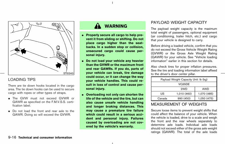
LOADING TIPSThere are tie down hooks located in the cargoarea. The tie down hooks can be used to securecargo with ropes or other types of straps.
� The GVW must not exceed GVWR orGAWR as specified on the F.M.V.S.S. certi-fication label.
� Do not load the front and rear axle to theGAWR. Doing so will exceed the GVWR.
WARNING
� Properly secure all cargo to help pre-vent it from sliding or shifting. Do notplace cargo higher than the seat-backs. In a sudden stop or collision,unsecured cargo could cause per-sonal injury.
� Do not load your vehicle any heavierthan the GVWR or the maximum frontand rear GAWRs. If you do, parts ofyour vehicle can break, tire damagecould occur, or it can change the wayyour vehicle handles. This could re-sult in loss of control and cause per-sonal injury.
� Overloading not only can shorten thelife of the vehicle and the tire, but canalso cause unsafe vehicle handlingand longer braking distances. Thismay cause a premature tire failurewhich could result in a serious acci-dent and personal injury. Failurescaused by overloading are not cov-ered by the vehicle’s warranty.
PAYLOAD WEIGHT CAPACITY
The payload weight capacity is the maximumtotal weight of passengers, optional equipment(air conditioning, trailer hitch, etc.) and cargothat your vehicle is designed to carry.
Before driving a loaded vehicle, confirm that youdo not exceed the Gross Vehicle Weight Rating(GVWR) or the Gross Axle Weight Rating(GAWR) for your vehicle. See “Vehicle loadinginformation” earlier in this section for details.
Also check tires for proper inflation pressures.See the tire and loading information label affixedto the driver’s door center pillar.
Payload Weight Capacity Unit: lb (kg)
VQ35DE
2WD AWD
US 1,010 (460) 1,070 (485)
Canada 990 (450) 1,050 (475)
MEASUREMENT OF WEIGHTSSecure loose items to prevent weight shifts thatcould affect the balance of your vehicle. Whenthe vehicle is loaded, drive to a scale and weighthe front and the rear wheels separately todetermine axle loads. Individual axle loadsshould not exceed either of the gross axle weightratings (GAWR). The total of the axle loads
STI0343
9-16 Technical and consumer information
� 04.8.3/Z50-D/V5.0 �

should not exceed the gross vehicle weightrating (GVWR). These ratings are given on thevehicle certification label that is located on thedriver’s door lock pillar. If weight ratings areexceeded, move or remove items to bring allweights below the ratings.
CAUTION
Overloading can shorten the life of yourvehicle. Failures caused by overloadingare not covered by your warranty.
WARNING
Overloading or improper loading of atrailer and its cargo can adversely affectvehicle handling, braking and perfor-mance and may lead to accidents.
CAUTION
� Do not tow a trailer or haul a heavyload for the first 500 miles (800 km).
Your engine, axle or other partscould be damaged.
� For the first 500 miles (800 km) thatyou tow a trailer, do not drive over 50mph (80 km/h) and do not makestarts at full throttle. This helps theengine and other parts of your ve-hicle wear in at the heavier loads.
Your new vehicle was designed to be usedprimarily to carry passengers and cargo. Re-member that towing a trailer will place additionalloads on your vehicle’s engine, drive train, steer-ing, braking and other systems.
A Nissan Trailer Towing Guide (US only) isavailable from a NISSAN dealer. This guideincludes information on trailer towing ability andthe special equipment required for proper tow-ing.
CA0009
TOWING A TRAILER
Technical and consumer information 9-17
� 04.8.3/Z50-D/V5.0 �

CAUTION
Vehicle damage resulting from im-proper towing procedures are not cov-ered by NISSAN warranties. A NISSANTrailer Towing Guide (U.S. only) contain-ing information on trailer towing abilityand the special equipment required maybe obtained from a NISSAN dealer.
MAXIMUM LOAD LIMITS
Maximum trailer loads
Never allow the total trailer load to exceed thevalue specified in the Towing Load/SpecificationChart found later in this section. The total trailerload equals trailer weight plus its cargo weight.
� When towing a trailer load of 1,000 lbs. (454kg) or more, trailers with a brake systemMUST be used.
The maximum GCWR (Gross CombinedWeightRating) should not exceed the value specified inthe following Towing Load/Specification Chart.
The GCWR equals the combined weight of thetowing vehicle (including passengers and cargo)plus the total trailer load. Towing loads greater
than these or using improper towing equipmentcould adversely affect vehicle handling, brakingand performance.
The ability of your vehicle to tow a trailer is notonly related to the maximum trailer loads, butalso the places you plan to tow. Tow weightsappropriate for level highway driving may have tobe reduced on very steep grades or in lowtraction situations (for example, on slippery boatramps).
Temperature conditions also can affect towing.For example, towing a heavy trailer in highoutside temperatures on graded roads can af-fect engine performance and cause overheating.The transmission high fluid temperature protec-tion mode, which helps reduce the chance oftransmission damage, could activate and auto-matically decrease engine power. Vehicle speedmay decrease to 40 to 50 MPH (65 to 80 km/h)under high load. Plan your trip carefully to ac-count for trailer and vehicle load, weather, androad conditions.
WARNING
Overheating can result in reduced en-gine power and vehicle speed. Also,
when the high temperature mode oper-ates, vehicle speed may be graduallyreduced. The reduced speed may belower than other traffic, which couldincrease the chance of a collision. Beespecially careful when driving. If nec-essary, pull to the side of the road at asafe place and allow the engine to coolor the transmission to return to normaloperation.
Tongue loadKeep the tongue load between 9 to 11% of thetotal trailer load within the maximum tongue loadlimits shown in the following TowingLoad/Specifications Chart. If the tongue loadbecomes excessive, rearrange cargo to allow forproper tongue load.
9-18 Technical and consumer information
� 04.8.3/Z50-D/V5.0 �
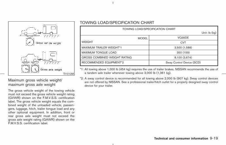
Maximum gross vehicle weight/maximum gross axle weightThe gross vehicle weight of the towing vehiclemust not exceed the gross vehicle weight rating(GVWR) shown on the F.M.V.S.S. certificationlabel. The gross vehicle weight equals the com-bined weight of the unloaded vehicle, passen-gers, luggage, hitch, trailer tongue load and anyother optional equipment. In addition, front orrear gross axle weight must not exceed thegross axle weight rating (GAWR) shown on theF.M.V.S.S. certification label.
TOWING LOAD/SPECIFICATION CHART
TOWING LOAD/SPECIFICATION CHARTUnit: lb (kg)
MODELWEIGHT
VQ35DE
CVT
MAXIMUM TRAILER WEIGHT*1 3,500 (1,588)
MAXIMUM TONGUE LOAD 350 (159)
GROSS COMBINED WEIGHT RATING 8,100 (3,674)
RECOMMENDED EQUIPMENT*2 Sway Control Device (SCD)
*1: All towing above 1,000 lb (454 kg) requires the use of trailer brakes. NISSAN recommends the use ofa tandem axle trailer whenever towing above 3,000 lb (1,361 kg).
*2: A sway control device is recommended for all towing above 2,000 lb (907 kg). Sway control devicesare not offered by NISSAN. See a professional trailer/hitch outlet for a properly designed sway controldevice for your trailer.
TI1012M
Technical and consumer information 9-19
� 04.8.3/Z50-D/V5.0 �

TOWING SAFETY
Trailer hitchChoose a proper hitch for your vehicle andtrailer. A genuine NISSAN trailer hitch is avail-able from a NISSAN dealer. Make sure the trailerhitch is securely attached to the vehicle, to helpavoid personal injury or property damage due tosway caused by crosswinds, rough road sur-faces or passing trucks.
Trailer hitchChoose a proper hitch for your vehicle andtrailer. Make sure the trailer hitch is securelyattached to the vehicle, to help avoid personalinjury or property damage due to sway causedby crosswinds, rough road surfaces or passingtrucks.
Hitch ballChoose a hitch ball of the proper size and weightrating for your trailer:
� The required hitch ball size is stamped onmost trailer couplers. Most hitch balls alsohave the size printed on top of the ball.
� Choose the proper class hitch ball based onthe trailer weight.
� The diameter of the threaded shank of thehitch ball must be matched to the ball mount
hole diameter. The hitch ball shank should beno more than 1/16″ smaller than the hole inthe ball mount.
� The threaded shank of the hitch ball must belong enough to be properly secured to theball mount. There should be at least 2 threadsshowing beyond the lock washer and nut.
Class I hitch
Class I trailer hitch equipment (receiver, ballmount and hitch ball) can be used to tow trailersof a maximum weight of 2,000 lb (909 kg).
You may add Class I trailer hitch equipment tothe vehicle that has a 2,000 lb (909 kg) maxi-mum weight rating, but your vehicle is onlycapable of towing the maximum trailer weightsshown in the Towing Load/Specification Chartearlier in this section.
CAUTION
� Special hitches which include framereinforcements are required for tow-ing above 2,000 lb (907 kg). Suitablegenuine NISSAN hitches for pickuptrucks and sport utility vehicles areavailable at a NISSAN dealer.
� Do not use axle-mounted hitches.
� The hitch should not be attached toor affect the operation of the impact-absorbing bumper.
� Do not modify the vehicle exhaustsystem, brake system, etc. to install atrailer hitch.
� After the hitch is removed, seal thebolt holes to prevent exhaust fumes,water or dust from entering the pas-senger compartment.
� Regularly check that all trailer hitchmounting bolts are securelymounted.
� To reduce the possibility of addi-tional damage if your vehicle isstruck from the rear, where practical,remove the hitch and/or receiverwhen not in use.
Tire pressures
� When towing a trailer, inflate the vehicle tiresto the recommended cold tire pressure indi-cated on the Tire and Loading Information
9-20 Technical and consumer information
� 04.8.3/Z50-D/V5.0 �

label (located on the driver’s door centerpillar).
� Trailer tire condition, size, load rating andproper inflation pressure should be in accor-dance with the trailer and tire manufacturers’specifications.
Safety chainAlways use a suitable chains between yourvehicle and the trailer. The safety chains shouldbe crossed and should be attached to the hitch,not to the vehicle bumper or axle. Be sure toleave enough slack in the chain to permit turningcorners.
Trailer lights
CAUTION
When splicing into the vehicle electricalsystem, a commercially availablepower-type module/converter must beused to provide power for all trailerlighting. This unit uses the vehicle bat-tery as a direct power source for alltrailer lights while using the vehicle taillight, stoplight and turn signal circuitsas a signal source. The module/
converter must draw no more than 15milliamps from the stop and tail lampcircuits. Using a module/converter thatexceeds these power requirements maydamage the vehicle’s electrical system.See a reputable trailer dealer to obtainthe proper equipment and to have itinstalled.
Trailer lights should comply with federal and/orlocal regulations. For assistance in hooking uptrailer lights, contact a NISSAN dealer or repu-table trailer dealer.
Trailer brakes
If your trailer is equipped with a braking system,make sure it conforms to federal and/or localregulations and that it is properly installed.
WARNING
Never connect a trailer brake systemdirectly to the vehicle brake system.
Pre-towing tips� Be certain your vehicle maintains a level
position when a loaded and/or unloadedtrailer is hitched. Do not drive the vehicle if ithas an abnormal nose-up or nose-down con-dition; check for improper tongue load, over-load, worn suspension or other possiblecauses of either condition.
� Always secure items in the trailer to preventload shifts while driving.
� Load the trailer so approximately 60% of thetrailer load is in the front half and 40% is inthe back half.
� Check your hitch, trailer tire pressure, vehicletire pressure, trailer light operation, and trailerwheel lug nuts every time you attach a trailerto the vehicle.
� Be certain your rear view mirrors conform toall federal, state or local regulations. If not,install any mirrors required for towing beforedriving the vehicle.
Trailer towing tipsIn order to gain skill and an understanding of thevehicle’s behavior, you should practice turning,stopping and backing up in an area which is freefrom traffic. Steering stability, and braking per-formance will be somewhat different than undernormal driving conditions.
� Always secure items in the trailer to prevent
Technical and consumer information 9-21
� 04.8.3/Z50-D/V5.0 �

load shift while driving.
� Avoid abrupt starts, acceleration or stops.
� Avoid sharp turns or lane changes.
� Always drive your vehicle at a moderatespeed. Some states or provinces have spe-cific speed limits for vehicles that are towingtrailers. Obey the local speed limits.
� When backing up, hold the bottom of thesteering wheel with one hand. Move yourhand in the direction in which you want thetrailer to go. Make small corrections and backup slowly. If possible, have someone guideyou when you are backing up.
� Always block the wheels on both vehicle andtrailer when parking. Parking on a slope is notrecommended; however, if you must do so,first block the wheels and apply the parkingbrake, and then move the shift lever into the P(Park) position. If you move the shift lever tothe P (Park) position before blocking thewheels and applying the parking brake, trans-mission damage could occur.
� When going down a hill, shift into a lowergear and use the engine braking effect.When going up a long grade, downshift thetransmission to a lower gear and reducespeed to reduce chances of engine overload-ing and/or overheating.
� If the engine coolant rises to an extremelyhigh temperature when the air conditioningsystem is on, turn off the air conditioner.Coolant heat can be additionally vented byopening the windows, switching the fan con-trol to high and setting the temperature con-trol to the HOT position.
� If the transmission fluid rises to an extremelyhigh temperature, a high fluid temperatureprotection mode may operate. See page5-13 for details. If necessary, pull to the sideof the road at a safe place and let thetransmission cool before continuing.
� Trailer towing requires more fuel than normalcircumstances.
� Avoid towing a trailer for the first 500 miles(800 km).
� Have your vehicle serviced more often than atintervals specified in the recommended main-tenance schedule.
� When making a turn, your trailer wheels willbe closer to the inside of the turn than yourvehicle wheels. To compensate for this, makea larger than normal turning radius during theturn.
� Crosswinds and rough roads will adverselyaffect vehicle/trailer handling, possibly caus-ing vehicle sway. When being passed by
larger vehicles, be prepared for possiblechanges in crosswinds that could affect ve-hicle handling. If swaying does occur, firmlygrip the steering wheel, steer straight ahead,and immediately (but gradually) reduce ve-hicle speed. This combination will help stabi-lize the vehicle. Never increase speed.
� Be careful when passing other vehicles.Passing while towing a trailer requires con-siderably more distance than normal passing.Remember the length of the trailer must alsopass the other vehicle before you can safelychange lanes.
� Avoid holding the brake pedal down too longor too frequently. This could cause the brakesto overheat, resulting in reduced braking ef-ficiency.
� Increase your following distance to allow forgreater stopping distances while towing atrailer. Anticipate stops and brake gradually.
� Do not use cruise control while towing atrailer.
� Check your hitch, trailer wiring harness con-nections, and trailer wheel lug nuts after 50miles (80 km) of travel and at every break.
� When stopped in traffic for long periods oftime in hot weather, put the vehicle in the P(Park) position.
9-22 Technical and consumer information
� 04.8.3/Z50-D/V5.0 �
DOT (Department Of Transportation) QualityGrades: All passenger car tires must conform tofederal safety requirements in addition to thesegrades.
Quality grades can be found where applicableon the tire sidewall between tread shoulder andmaximum section width. For example:
Treadwear 200 Traction AA Temperature A
Treadwear
Treadwear grade is a comparative rating basedon tire wear rate when tested under controlledconditions on specified government testcourses. For example, a tire graded 150 wouldwear one and a half (1-1/2) times as well on thegovernment course as a tire graded 100. How-ever, relative tire performance depends on actualdriving conditions, and may vary significantlyfrom the norm due to variations in driving habits,service practices and differences in road char-acteristics and climate.
Traction AA, A, B and C
The traction grades, from highest to lowest, areAA, A, B, and C. Those grades represent thetire’s ability to stop on wet pavement as mea-sured under controlled conditions on specifiedgovernment test surfaces of asphalt and con-
crete. A tire marked C may have poor tractionperformance.
WARNING
The traction grade assigned to your ve-hicle tires is based on straight-aheadbraking traction tests and does not in-clude acceleration, cornering, hydro-planing or peak traction characteristics.
Temperature A, B and CTemperature grades are A (the highest), B, andC. They represent a tire’s resistance to heatbuild-up, and its ability to dissipate heat whentested under controlled conditions on a speci-fied indoor laboratory test wheel. Sustained hightemperature can cause tire material to degener-ate, reducing tire life. Excessive temperaturescan lead to sudden tire failure. Grade C corre-sponds to a performance level which all passen-ger car tires must meet under the Federal MotorVehicle Safety Standard No. 109. Grades A andB represent higher levels of performance onlaboratory test wheels than the minimum re-quired by law.
WARNING
The temperature grade for this tire isestablished for a tire that is properlyinflated and not overloaded. Excessivespeed, under-inflation, or excessiveloading, either separately or in combi-nation, can cause heat build-up andpossible tire failure.
UNIFORM TIRE QUALITYGRADING
Technical and consumer information 9-23
� 04.8.3/Z50-D/V5.0 �

Your NISSAN is covered by the following emis-sion warranties.
For US:
� Emission Defects Warranty
� Emissions Performance Warranty(See Warranty Information Booklet for de-tails)
For Canada:
Emission Control System Warranty
Details of these warranties may be found withother vehicle warranties in your Warranty Infor-mation Booklet that comes with your NISSANvehicle. If you did not receive a Warranty Infor-mation Booklet or it has become lost, you mayobtain a replacement by writing to:
� Nissan North America, Inc.Consumer Affairs DepartmentP.O. Box 191Gardena, CA. 90248-0191
� Nissan Canada Inc.5290 Orbitor DriveMississauga, Ontario,L4W 4Z5
If you believe that your vehicle has adefect which could cause a crash orcould cause injury or death, you shouldimmediately inform the National High-way Traffic Safety Administration(NHTSA) in addition to notifyingNISSAN.
If NHTSA receives similar complaints,it may open an investigation, and if itfinds that a safety defect exists in agroup of vehicles, it may order a recalland remedy campaign. However,NHTSA cannot become involved inindividual problems between you, yourdealer, or NISSAN.
To contact NHTSA, you may call theAuto Safety Hotline toll-free at 1-888-327-4236. You may also write to:NHTSA, U.S. Department of Transpor-tation, Washington, D.C. 20590. Youcan also obtain other information aboutmotor vehicle safety from the Hotline.
You may notify NISSAN by contactingour Consumer Affairs Department, toll-free, at 1-800-662-6200.
WARNING
A vehicle equipped with AWD (All-Wheel Drive) should never be testedusing a two wheel dynamometer, similarto the dynamometers used by somestates for emissions testing, or similarequipment. Make sure you inform thetest facility personnel that your vehicleis an AWD equipped vehicle before it isplaced on a dynamometer. Failure to doso may result in transmission damageor unexpected vehicle movement whichcould result in serious vehicle damageor personal injury.
Due to legal requirements in some states/areas, your vehicle may be required to be in whatis called the “ready condition” for anInspection/Maintenance (I/M) test of the emis-sion control system.
The vehicle is set to the “ready condition” whenit is driven through certain driving patterns.Usually, the “ready condition” can be obtainedby ordinary usage of the vehicle.
If a powertrain system component is repaired or
EMISSION CONTROL SYSTEMWARRANTY
REPORTING SAFETY DEFECTS(US only)
READINESS FOR INSPECTION/MAINTENANCE (I/M) TEST (USonly)
9-24 Technical and consumer information
� 04.8.3/Z50-D/V5.0 �
the battery is disconnected, the vehicle may bereset to a not “ready condition”. Before takingthe I/M test, check the vehicle’s inspection/maintenance test readiness condition. Turn theignition switch ON without starting the engine. Ifthe Malfunction Indicator Lamp (MIL) comes onsteady for 20 seconds and then blinks for 10seconds, the I/M test condition is “not ready”. Ifthe MIL does not blink after 20 seconds, the I/Mtest condition is “ready”. If the MIL indicates thevehicle is in a “not ready” condition, drive thevehicle through the following pattern to set thevehicle to the ready condition. If you cannot ordo not want to perform the driving pattern, aNISSAN dealer can conduct it for you.
WARNING
Always drive the vehicle in a safe andprudent manner according to trafficconditions and obey all traffic laws.
1. Start the engine. Allow the engine to idle untilthe engine coolant temperature gauge needlepoints between the C and H (normal operat-ing temperature).
2. Accelerate the vehicle to 55 MPH (88 km/h),then quickly release the accelerator pedal
completely and keep it released for at least10 seconds.
3. Quickly depress the accelerator pedal for amoment, then drive the vehicle at a speed of53 to 60 MPH (86 to 96 km/h) for at least 9minutes.
4. Stop the vehicle. Leave the engine running.
5. Accelerate the vehicle to 35 MPH (55 km/h)and maintain the speed for 20 seconds.
6. Repeat steps 4 and 5 at least 10 times.
7. Accelerate the vehicle to 55 MPH (88 km/h)and maintain the speed for at least 3 minutes.
8. Stop the vehicle. Place the transmission shiftlever in the “P” or “N” position.
9. Turn the engine off.
10. Repeat steps 1 through 8 at least one moretime.
If step 1 through 7 is interrupted, repeat thepreceding step. Any safe driving mode is ac-ceptable between steps. Do not stop the engineuntil step 7 is completed.
Your vehicle is equipped with a variety of com-puters that monitor and control a number ofsystems to optimize performance and help ser-vice technicians with diagnosis and repair. De-pending on the equipment on your vehicle, someof the computers monitor emission control sys-tems, braking systems and air bag systems, justto name a few. Some data about vehicle opera-tion may be stored in the computers for useduring servicing. Other data may be stored if acrash event occurs. For example, air bag readi-ness, air bag performance, and seat belt use bythe driver or passenger may be recorded, de-pending on vehicle equipment. These types ofsystems are sometimes called Event Data Re-corders.
Special equipment can be used to access theelectronic data that may be stored in the vehi-cle’s computers (sounds are not recorded).NISSAN and NISSAN dealers have equipmentto access some of this data; others may alsohave this equipment. The data may be retrievedduring routine vehicle servicing or for specialresearch. It might also be accessed with theconsent of the vehicle owner or lessee, in re-sponse to a request by law enforcement, or asotherwise required or permitted by law.
EVENT DATA RECORDERS
Technical and consumer information 9-25
� 04.8.3/Z50-D/V5.0 �
A genuine NISSAN Service Manual is the bestsource of service and repair information for yourvehicle. Filled with wiring diagrams, illustrationsand step-by-step diagnostic and adjustmentprocedures, this manual is the same one used bythe factory trained technicians working at autho-rized NISSAN dealerships. Also available aregenuine NISSAN Owner’s Manuals, and genu-ine NISSAN Service and Owner’s Manuals forolder NISSAN models.
In the USA:
For current pricing and availability of genuineNISSAN Service Manuals for the 2000 modelyear and later, contact:
Tweddle Litho Company1-800-450-9491www.nissan-techinfo.com
For current pricing and availability of genuineNISSAN Service Manuals for the 1999 modelyear and prior, see a NISSAN dealer, or contact:
Resolve Corporation20770 Westwood Dr.Strongsville OH 441361-800-247-5321
For current pricing and availability of genuineNISSAN Owner’s Manuals for the 2005model year and prior, see a NISSAN dealer, orcontact:
Resolve Corporation20770 Westwood Dr.Strongsville OH 441361-800-247-5321
In Canada:
To purchase a copy of a genuine NISSANService Manual or Owner’s Manual please con-tact your nearest NISSAN dealer. For the phonenumber and location of a NISSAN Dealer in yourarea call the NISSAN Satisfaction Center at1-800-387-0122 and a bilingual NISSAN rep-resentative will assist you.
Also available are Genuine NISSAN Service andOwner’s Manuals for older NISSAN models.
IN THE EVENT OF A COLLISIONUnfortunately, accidents do occur. In this unlikelyevent, there is some important information youshould know. Many insurance companies rou-tinely authorize the use of non-genuine collisionparts in order to cut costs, among other reasons.
OWNER’S MANUAL/SERVICEMANUAL ORDER INFORMATION
9-26 Technical and consumer information
� 04.8.3/Z50-D/V5.0 �

Insist on the use of Genuine NISSANCollision Parts!
If you want your vehicle to be restored usingparts made to NISSAN’s original exacting speci-fications — if you want to help it to last and holdits resale value, the solution is simple. Tell yourinsurance agent and your repair shop toonly use Genuine NISSAN Collision Parts.NISSAN does not warrant non-NISSAN parts,nor does NISSAN’s warranty apply to damagecaused by a non-genuine part.
Using Genuine NISSAN Parts can help protectyour personal safety, preserve your warrantyprotection and maintain the resale value of yourvehicle. And if your vehicle was leased, usingGenuine NISSAN Parts may prevent or limitunnecessary excess wear and tear expenses atthe end of your lease.
NISSAN designs its hoods with crumple zonesto minimize the risk that the hood will penetratethe windshield of your vehicle in an accident.Non-genuine (imitation) parts may not providesuch built in safeguards. Also, non-genuineparts often show premature wear, rust and cor-rosion.
Why should you take a chance?In over 40 states, the law says you must beadvised if non-genuine parts are used to repair
your vehicle. And some states have enactedlaws that restrict insurance companies fromauthorizing the use of non-genuine collisionparts during the new vehicle warranty. Theselaws help protect you, so you can take action toprotect yourself.
It’s your right!If you should need further information visit us at:
www.nissanusa.com (for U.S. customers) orwww.nissancanada.com (for Canadian cus-tomers).
Technical and consumer information 9-27
� 04.8.3/Z50-D/V5.0 �

MEMO
9-28 Technical and consumer information
� 04.8.3/Z50-D/V5.0 �

10 Index
A
ABS (Anti-lock brake system)................................ 5-30ABS warning light ..................................................... 2-10Aiming control, Headlights...................................... 2-25Air bag.......................................................................... 1-39Air bag warning labels ............................................. 1-49Air bag warning light .................................... 1-50, 2-13Air cleaner filter.......................................................... 8-17Air conditioner
Air conditioner operation .................................. 4-20Air conditioner service........................... 4-20, 4-23Air conditioner specification label .................. 9-12Air conditioning system refrigerantand lubricant recommendations ............ 4-23, 9-6Heater and air conditioner (automatic) ......... 4-20In-cabin microfilter.............................................. 4-23
Alcohol, drugs and driving......................................... 5-5All wheel drive (AWD) ............................................. 5-24All wheel drive (AWD), AWD lock switchoperations.................................................................... 5-24All wheel drive (AWD), LOCK indicator light(AWD models) ........................................................... 2-14Anchor point locations
Top tether strap .................................................. 1-30Antenna........................................................................ 4-36Anti-lock Brake System (ABS) .............................. 5-30Appearance care
Exterior appearance care .................................... 7-2
Interior appearance care ..................................... 7-3Armrest ........................................................................... 1-9Audible reminders ..................................................... 2-16Audio operation precautions .................................. 4-25Audio system.............................................................. 4-24Autochanger, Compact Disc (CD) ....................... 4-33Autolight system ........................................................ 2-23Automatic
Anti-glare inside mirror...................................... 3-31Automatic sunroof .............................................. 2-37Drive positioner ................................................... 3-33Seat positioner, seat.......................................... 3-33
Avoiding collision and rollover.................................. 5-5
B
Back door.................................................................... 3-25Battery.......................................................................... 8-14
Battery saver system ......................................... 2-24Battery replacement
Intelligent Key system .......................................... 3-8Remote keyless entry system............................. 3-8
Before starting the engine ...................................... 5-11Belts (See drive belts) ............................................. 8-16Booster seats ............................................................. 1-34Brake
Anti-lock brake system (ABS)......................... 5-30Brake booster ...................................................... 8-21Brake fluid............................................................. 8-13
Brake pedal .......................................................... 8-20Brake pedal check ............................................. 8-20Brake system ....................................................... 5-29Parking brake check............................... 5-20, 8-20Parking brake operation.................................... 5-20Warning light ....................................................... 2-10
Break-in schedule ..................................................... 5-23Brightness control, Instrument panel ................... 2-26Bulb check/instrument panel .................................... 2-9Bulb replacement ...................................................... 8-26
C
Cabin air filter............................................................. 4-23Capacities and recommended fuel/lubricants...... 9-2Car phone or CB radio............................................ 4-36Cargo (See vehicle loading information)............. 2-34Cargo net .................................................................... 2-34Cassette player (See audio system) .................... 4-31CD care and cleaning.............................................. 4-34Ceiling light................................................................. 2-39Cellular phone holder............................................... 2-31Child restraints........................................................... 1-21
Booster seats ...................................................... 1-34Installation on front passenger seat............... 1-31Installation on rear seat outboard or centerpositions................................................................ 1-22LATCH (Lower Anchors and Tethers forCHildren) system................................................ 1-27
� 04.8.3/Z50-D/V5.0 �

Precautions on child restraints........................ 1-21Top tether strap anchor point locations ....... 1-30With top tether strap ......................................... 1-29
Child safety ................................................................. 1-12Child safety rear door lock........................................ 3-5Chimes, Audible reminders..................................... 2-16Circuit breaker, Fusible link .................................... 8-21Class I hitch................................................................ 9-20Cleaning exterior and interior .......................... 7-2, 7-3Clock ................................................................... 4-4, 4-15Coin box ...................................................................... 2-30Cold weather driving ................................................ 5-33Compact Disc (CD) changer operation .............. 4-33Compact Disc (CD) player (See audiosystem)......................................................................... 4-32Compass display ......................................................... 2-6Console box................................................................ 2-33Continuously Variable Transmission (CVT)indicator light.............................................................. 2-14Control panel buttons (models with navigationsystem) ........................................................................... 4-8Control panel buttons (models withoutnavigation system) ....................................................... 4-2Controls
Control panel buttons (display withnavigation system) ................................................ 4-8Control panel buttons (display withoutnavigation system) ................................................ 4-2Heater and air conditioner controls(automatic)............................................................ 4-20
CoolantCapacities and recommended fuel/lubricants ................................................................. 9-2Changing engine coolant .................................... 8-9Checking engine coolant level........................... 8-8
Corrosion protection ................................................... 7-5Cover, Tonneau cover.............................................. 2-34Cruise control............................................................. 5-21Cruise set indicator light ......................................... 2-14Cup holders ................................................................ 2-31CVT, Driving with CVT (ContinuouslyVariable Transmission) ............................................. 5-12CVT fluid...................................................................... 8-12CVT, Transmission selector lever lockrelease .............................................................. 5-15, 5-19
D
Daytime running light system ................................. 2-25Defroster switch, Rear window and outsidemirror defroster switch............................................. 2-21Dimensions and weights............................................ 9-9Display controls (See control panel buttons),With navigation system .............................................. 4-8Display controls (See control panel buttons),Without navigation system ........................................ 4-2Door open warning light.......................................... 2-11Drive belts ................................................................... 8-16Drive positioner, Automatic..................................... 3-33Driving
All wheel drive (AWD)....................................... 5-24Cold weather driving ......................................... 5-33Driving with CVT (Continuously VariableTransmission)....................................................... 5-12On-pavement and offroad driving..................... 5-5Precautions when starting and driving ............ 5-2Safety precautions ................................................ 5-6
E
Economy, Fuel............................................................ 5-23Entry/exit function...................................................... 3-33Emission control information label ........................ 9-11Emission control system warranty......................... 9-24Engine
Before starting the engine................................ 5-11Break-in schedule............................................... 5-23Capacities and recommended fuel/lubricants ................................................................. 9-2Changing engine coolant .................................... 8-9Changing engine oil ........................................... 8-10Changing engine oil filter ................................. 8-11Checking engine coolant level........................... 8-8Checking engine oil level .................................... 8-9Coolant temperature gauge ............................... 2-5Engine block heater ........................................... 5-34Engine compartment check locations.............. 8-7Engine cooling system......................................... 8-8Engine oil................................................................. 8-9Engine oil and oil filter recommendation......... 9-5Engine oil viscosity ............................................... 9-5Engine serial number ......................................... 9-11Engine specifications ........................................... 9-8If your vehicle overheats ................................... 6-11Starting the engine............................................. 5-12
Event data recorders................................................ 9-25Exhaust gas (Carbon monoxide).............................. 5-2
F
F.M.V.S.S. certification label................................... 9-11
� 04.8.3/Z50-D/V5.0 �
10-2
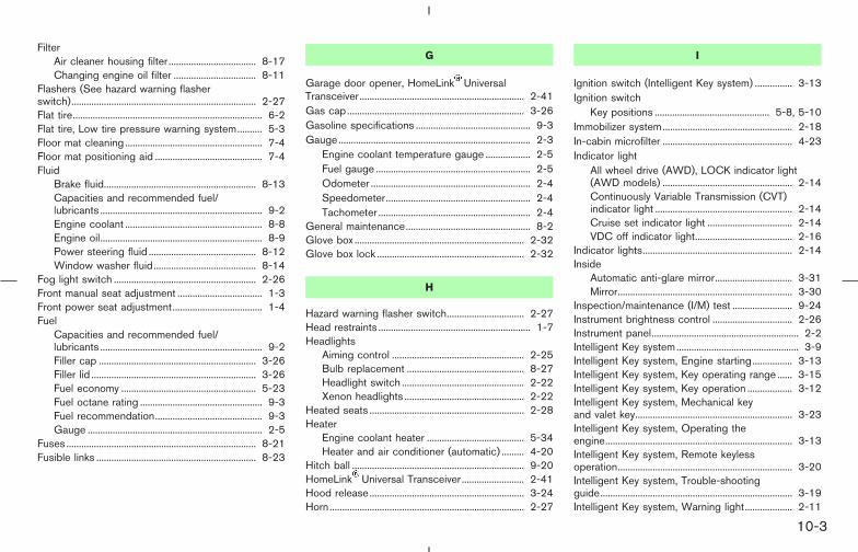
FilterAir cleaner housing filter ................................... 8-17Changing engine oil filter ................................. 8-11
Flashers (See hazard warning flasherswitch).......................................................................... 2-27Flat tire............................................................................ 6-2Flat tire, Low tire pressure warning system.......... 5-3Floor mat cleaning ....................................................... 7-4Floor mat positioning aid ........................................... 7-4Fluid
Brake fluid............................................................. 8-13Capacities and recommended fuel/lubricants ................................................................. 9-2Engine coolant ....................................................... 8-8Engine oil................................................................. 8-9Power steering fluid ........................................... 8-12Window washer fluid......................................... 8-14
Fog light switch ......................................................... 2-26Front manual seat adjustment .................................. 1-3Front power seat adjustment.................................... 1-4Fuel
Capacities and recommended fuel/lubricants ................................................................. 9-2Filler cap ............................................................... 3-26Filler lid .................................................................. 3-26Fuel economy ...................................................... 5-23Fuel octane rating ................................................. 9-3Fuel recommendation........................................... 9-3Gauge ...................................................................... 2-5
Fuses ............................................................................ 8-21Fusible links ................................................................ 8-23
G
Garage door opener, HomeLink UniversalTransceiver.................................................................. 2-41Gas cap....................................................................... 3-26Gasoline specifications .............................................. 9-3Gauge............................................................................. 2-3
Engine coolant temperature gauge .................. 2-5Fuel gauge .............................................................. 2-5Odometer ................................................................ 2-4Speedometer.......................................................... 2-4Tachometer ............................................................. 2-4
General maintenance.................................................. 8-2Glove box .................................................................... 2-32Glove box lock ........................................................... 2-32
H
Hazard warning flasher switch............................... 2-27Head restraints ............................................................. 1-7Headlights
Aiming control ..................................................... 2-25Bulb replacement ............................................... 8-27Headlight switch ................................................. 2-22Xenon headlights ................................................ 2-22
Heated seats .............................................................. 2-28Heater
Engine coolant heater ....................................... 5-34Heater and air conditioner (automatic) ......... 4-20
Hitch ball ..................................................................... 9-20HomeLink Universal Transceiver ......................... 2-41Hood release.............................................................. 3-24Horn.............................................................................. 2-27
I
Ignition switch (Intelligent Key system) ............... 3-13Ignition switch
Key positions .............................................. 5-8, 5-10Immobilizer system.................................................... 2-18In-cabin microfilter .................................................... 4-23Indicator light
All wheel drive (AWD), LOCK indicator light(AWD models) .................................................... 2-14Continuously Variable Transmission (CVT)indicator light ....................................................... 2-14Cruise set indicator light .................................. 2-14VDC off indicator light....................................... 2-16
Indicator lights............................................................ 2-14Inside
Automatic anti-glare mirror............................... 3-31Mirror...................................................................... 3-30
Inspection/maintenance (I/M) test ........................ 9-24Instrument brightness control ................................ 2-26Instrument panel........................................................... 2-2Intelligent Key system................................................. 3-9Intelligent Key system, Engine starting................ 3-13Intelligent Key system, Key operating range ...... 3-15Intelligent Key system, Key operation .................. 3-12Intelligent Key system, Mechanical keyand valet key............................................................... 3-23Intelligent Key system, Operating theengine........................................................................... 3-13Intelligent Key system, Remote keylessoperation...................................................................... 3-20Intelligent Key system, Trouble-shootingguide............................................................................. 3-19Intelligent Key system, Warning light................... 2-11
� 04.8.3/Z50-D/V5.0 �
10-3

Intelligent Key system, Warning signals.............. 3-17Intelligent key warning light .................................... 2-11Interior light replacement......................................... 8-28Interior lights ............................................................... 2-39
J
Jump starting................................................................. 6-8
K
Keyless entryWith Intelligent Key system (SeeIntelligent Key system) ...................................... 3-20Without Intelligent Key system (Seeremote keyless entry system)............................. 3-5
Keys................................................................................. 3-2Keys, For Intelligent Key system.............................. 3-9
L
Label, Air conditioner specification label ............ 9-12Label, Emission control information label............ 9-11Label, F.M.V.S.S. certification label ...................... 9-11Labels
Air bag warning labels ...................................... 1-49Engine serial number ......................................... 9-11Vehicle identification number (VIN)................ 9-10
LATCH (Lower Anchors and Tethers forCHildren) system....................................................... 1-27License plate, Installing front license plate......... 9-13Light
Air bag warning light ......................................... 1-50
Bulb replacement ............................................... 8-26Ceiling light .......................................................... 2-39Fog light switch................................................... 2-26Headlight switch ................................................. 2-22Headlights Bulb replacement .......................... 8-27Interior lights ........................................................ 2-39Luggage light....................................................... 2-41Map light ............................................................... 2-40Rear personal light ............................................. 2-40Replacement ........................................................ 8-26Vanity mirror light................................................ 2-41Warning/indicator lights and audiblereminders ..................................................... 2-9, 2-14Xenon headlights ................................................ 2-22
Lights, Exterior and interior lightreplacement ................................................................ 8-28Loading information (See vehicle loadinginformation) ................................................................. 9-14Lock
Back door lock .................................................... 3-25Door locks............................................................... 3-3Entry/exit function ............................................... 3-33Glove box lock..................................................... 2-32Lockout protection................................................ 3-5Power door lock .................................................... 3-3
Lockout protection....................................................... 3-5Low fuel warning light.............................................. 2-12Low tire pressure warning light ............................. 2-12Low tire pressure warning system ................. 5-3, 6-2Luggage light ............................................................. 2-41
M
MaintenanceBattery ................................................................... 8-14General maintenance ........................................... 8-2Inside the vehicle................................................... 8-3Maintenance notice............................................ 4-11Maintenance precautions .................................... 8-5Maintenance requirements.................................. 8-2Outside the vehicle............................................... 8-2Seat belt maintenance ...................................... 1-20Under the hood and vehicle............................... 8-4
Maintenance notice................................................... 4-11Malfunction indicator lamp (MIL)........................... 2-14Map light...................................................................... 2-40Mechanical key (for Intelligent Key system) ....... 3-23Meters and gauges ..................................................... 2-3Meters and gauges, Instrument brightnesscontrol .......................................................................... 2-26Mirror
Automatic anti-glare inside mirror .................. 3-31Inside mirror ......................................................... 3-30Outside mirror control ....................................... 3-32Outside mirrors ................................................... 3-32
N
Net, Cargo net ........................................................... 2-34New vehicle break-in................................................ 5-23Nissan Vehicle Immobilizer System...................... 2-17
Engine start ................................................. 5-9, 5-11
� 04.8.3/Z50-D/V5.0 �
10-4

O
Odometer....................................................................... 2-4Oil
Capacities and recommended fuel/lubricants ................................................................. 9-2Changing engine oil ........................................... 8-10Checking engine oil level .................................... 8-9Engine oil................................................................. 8-9Engine oil viscosity ............................................... 9-5
Operating the engine (Intelligent Keysystem)......................................................................... 3-13Outside mirror control.............................................. 3-32Outside mirrors .......................................................... 3-32Overheat, If your vehicle overheats ...................... 6-11Owner’s Manual/Service Manual orderinformation................................................................... 9-26
P
ParkingBrake check ......................................................... 8-20Parking brake check .......................................... 5-20Parking brake operation.................................... 5-20Parking on hills .................................................... 5-20
Parking/parking on hills ........................................... 5-28Pedal position adjustment....................................... 3-29Phone, Car phone or CB radio ............................. 4-36Power
Front seat adjustment .......................................... 1-4Power door lock .................................................... 3-3Power outlet......................................................... 2-29Power steering fluid ........................................... 8-12
Power steering system...................................... 5-29Power windows................................................... 2-35
P position selecting warning light......................... 2-13Pre-tensioner seat belt system.............................. 1-48Precautions
Audio operation................................................... 4-25Booster seats ...................................................... 1-34Braking precautions ........................................... 5-29Child restraints .................................................... 1-21Cruise control ...................................................... 5-21Driving safety.......................................................... 5-6Maintenance ........................................................... 8-5On-pavement and offroad driving..................... 5-5Seat belt usage ..................................................... 1-9Supplemental restraint system........................ 1-39When starting and driving .................................. 5-2
Push starting .............................................................. 6-10
R
Radio, Car phone or CB radio .............................. 4-36Readiness for inspection/maintenance (I/M)test (US only) ............................................................. 9-24Rear center seat belt................................................ 1-17Rear door lock, Child safety rear door lock.......... 3-5Rear personal light.................................................... 2-40Rear power point....................................................... 2-29Rear seat adjustment.................................................. 1-5Rear view monitor ..................................................... 4-17Rear window and outside mirror defrosterswitch ........................................................................... 2-21Rear window wiper and washer switch .............. 2-21Registering your vehicle in another country ....... 9-10
Remote keyless entrySystem, Except Intelligent Key system............ 3-5System, For Intelligent Key system................ 3-20
Reporting safety defects (US only) ...................... 9-24Rollover........................................................................... 5-5
S
SafetyChild seat belts ................................................... 1-12Reporting safety defects (US only)................ 9-24Towing safety....................................................... 9-20
Safety chain ................................................................ 9-21Seat belt warning chime ......................................... 2-16Seat belt warning light.................................... 1-9, 2-13Seat adjustment
Front manual seat adjustment............................ 1-3Front power seat adjustment ............................. 1-4Rear seat adjustment ........................................... 1-5
Seat belt(s)Child safety .......................................................... 1-12Injured persons.................................................... 1-13Larger children .................................................... 1-13Pre-tensioner seat belt system ....................... 1-48Precautions on seat belt usage......................... 1-9Pregnant women................................................. 1-13Rear center seat belt ......................................... 1-17Seat belt cleaning ................................................. 7-4Seat belt extenders ............................................ 1-20Seat belt hook ..................................................... 1-17Seat belt maintenance ...................................... 1-20Seat belts ................................................................ 1-9Shoulder belt height adjustment..................... 1-16Three-point type with retractor ....................... 1-13
� 04.8.4/Z50-D/V5.0 �
10-5
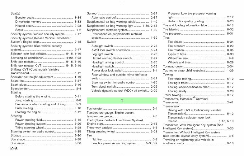
Seat(s)Booster seats ...................................................... 1-34Driver-side memory ............................................ 3-33Heated seats........................................................ 2-28Seats ........................................................................ 1-2
Security system, Vehicle security system ........... 2-17Security systems (Nissan Vehicle ImmobilizerSystem), Engine start ............................................... 2-18Security systems (See vehicle securitysystem)......................................................................... 2-17Selector lever lock release.......................... 5-15, 5-19Servicing air conditioner .............................. 4-20, 4-23Shift lock release ........................................... 5-15, 5-19Shift lock release, CVT ................................ 5-15, 5-19Shifting, CVT (Continuously VariableTransmission) ............................................................. 5-12Shoulder belt height adjustment ........................... 1-16Spare tire..................................................................... 8-37Spark plugs................................................................. 8-16Speedometer ................................................................ 2-4Starting
Before starting the engine................................ 5-11Jump starting .......................................................... 6-8Precautions when starting and driving ............ 5-2Push starting........................................................ 6-10Starting the engine............................................. 5-12
SteeringPower steering fluid ........................................... 8-12Power steering system...................................... 5-29Tilting steering wheel......................................... 3-28
Steering switch for audio control.......................... 4-35Storage ........................................................................ 2-30Sun shade................................................................... 2-38Sun visors ................................................................... 3-30
Sunroof ........................................................................ 2-37Automatic sunroof .............................................. 2-37
Supplemental air bag warning labels................... 1-49Supplemental air bag warning light .......... 1-50, 2-13Supplemental restraint system............................... 1-39
Precautions on supplemental restraintsystem.................................................................... 1-39
SwitchAutolight switch .................................................. 2-23AWD lock switch operations........................... 5-24Fog light switch................................................... 2-26Hazard warning flasher switch ........................ 2-27Headlight aiming control................................... 2-25Headlight switch ................................................. 2-22Power door lock switch....................................... 3-4Rear window and outside mirror defrosterswitch..................................................................... 2-21Steering switch for audio control ................... 4-35Turn signal switch .............................................. 2-26Vehicle dynamic control (VDC) off switch... 2-29
T
Tachometer.................................................................... 2-4Temperature gauge, Engine coolanttemperature gauge ...................................................... 2-5Theft (Nissan Vehicle Immobilizer System),Engine start................................................................. 2-18Three-way catalyst....................................................... 5-3Tilting steering wheel ............................................... 3-28Tire
Flat tire ..................................................................... 6-2Low tire pressure warning system........... 5-3, 6-2
Pressure, Low tire pressure warninglight......................................................................... 2-12Uniform tire quality grading.............................. 9-23
Tire and loading information label......................... 9-12Tire labeling ................................................................ 8-32Tire pressure............................................................... 8-31Tires
Tire chains ............................................................ 8-34Tire pressure........................................................ 8-29Tire rotation .......................................................... 8-35Types of tires ....................................................... 8-33Wheel/tire size ....................................................... 9-9Wheels and tires ................................................ 8-29
Tonneau cover ........................................................... 2-34Top tether strap child restraints ............................ 1-29Towing
Tow truck towing ................................................ 6-12Towing a trailer.................................................... 9-17Towing load/specification chart ...................... 9-17Towing safety....................................................... 9-20
Trailer towing.............................................................. 9-17Transceiver, HomeLink UniversalTransceiver.................................................................. 2-41Transmission
Driving with CVT (Continuously VariableTransmission)....................................................... 5-12Transmission selector lever lockrelease ....................................................... 5-15, 5-19
Transmitter, With Intelligent Key system (SeeIntelligent Key system) ............................................. 3-20Transmitter, Without Intelligent Key system(See remote keyless entry system) ......................... 3-5Traveling or registering your vehicle inanother country .......................................................... 9-10
� 04.8.4/Z50-D/V5.0 �
10-6

Trouble-shooting guide (for Intelligent Keysystem)......................................................................... 3-19Turn signal switch ..................................................... 2-26
U
Underbody cleaning .................................................... 7-3Uniform tire quality grading .................................... 9-23
V
Valet key (for Intelligent Key system).......... 3-2, 3-23Vanity mirror light ...................................................... 2-41VDC off indicator light ............................................. 2-16Vehicle
Dimensions and weights ..................................... 9-9Floor mat positioning aid..................................... 7-4Identification number (VIN)............................... 9-10Loading information............................................ 9-14Recovery (freeing a stuck vehicle) ................. 6-14Security system................................................... 2-17Vehicle dynamic control (VDC) offswitch..................................................................... 2-29Vehicle dynamic control (VDC) system ........ 5-31Vehicle electronic systems............................... 4-13
Vehicle load capacity ............................................... 9-15Ventilators.................................................................... 4-19
W
Warning labels, Air bag warning labels .............. 1-49Warning light
ABS warning light .............................................. 2-10
Air bag warning light.............................. 1-50, 2-13AWD warning light............................................. 5-26Brake warning light ............................................ 2-10Door open warning light ................................... 2-11Intelligent Key warning light ............................. 2-11Low fuel warning light ....................................... 2-12Low tire pressure warning light ...................... 2-12P position selecting warning light .................. 2-13Seat belt warning light ...................................... 2-13
Warning lights .............................................................. 2-9Warning, Hazard warning flasher switch ............ 2-27Warning, Low tire pressure warningsystem.................................................................... 5-3, 6-2Warning, Warning/indicator lights andaudible reminders ........................................................ 2-9Warranty, Emission control system warranty ..... 9-24Washer switch
Rear window wiper and washer switch........ 2-21Windshield wiper and washer switch ........... 2-20
Washing ......................................................................... 7-2Waxing............................................................................ 7-2Weights (See dimensions and weights) ............... 9-9Wheel/tire size.............................................................. 9-9Wheels and tires ....................................................... 8-29
Cleaning aluminum alloy wheels ....................... 7-3Window washer fluid ............................................... 8-14Window(s)
Cleaning................................................................... 7-3Power windows................................................... 2-35
Windshield wiper and washer switch.................. 2-20Wiper
Rear window wiper and washer switch........ 2-21Rear window wiper blade................................. 8-20Windshield wiper and washer switch ........... 2-20
Wiper blades ....................................................... 8-18
X
Xenon headlights....................................................... 2-22
� 04.8.4/Z50-D/V5.0 �
10-7

MEMO
10-8
� 04.8.4/Z50-D/V5.0 �

FUEL RECOMMENDATION:Use unleaded regular gasoline with an oc-tane rating of at least 87 AKI (Anti-KnockIndex) number (Research octane number91).
For improved vehicle performance,NISSAN recommends the use of unleadedpremium gasoline with an octane rating ofat least 91 AKI number (Research octanenumber 96).
CAUTION
Using a fuel other than that specifiedcould adversely affect the emission con-trol system, and may also affect thewarranty coverage.
Under no circumstances should aleaded gasoline be used, since this willdamage the three-way catalyst.
For additional information, see “Capacities andrecommended fuel/lubricants” in the “9. Techni-cal and consumer information” section.
ENGINE OIL RECOMMENDATION:� API Certification Mark
� API grade SG/SH, Energy Conserving I & IIor API grade SJ or SL, Energy Conserving
� ILSAC grade GF-I, GF-II & GF-III
� SAE 5W-30 viscosity oil is preferred for allambient temperatures. SAE 10W-30,10W-40 viscosity oil may be used for ambi-ent temperatures above 0°F (−18°C).
See “Capacities and recommended fuel/lubricants” in the “9. Technical and consumerinformation” section for engine oil and oil filterrecommendation.
COLD TIRE PRESSURES:See Tire and Loading Information label affixed tothe inside of the driver side center pillar.
NEW VEHICLE BREAK-INPROCEDURESRECOMMENDATION:During the first 1,200 miles (2,000 km) of ve-hicle use, follow the recommendations outlinedin the “Break-in schedule” Information found inthe “5. Starting and driving” section of thisOwner’s Manual.
GAS STATION INFORMATION
10-9
� 04.8.4/Z50-D/V5.0 �
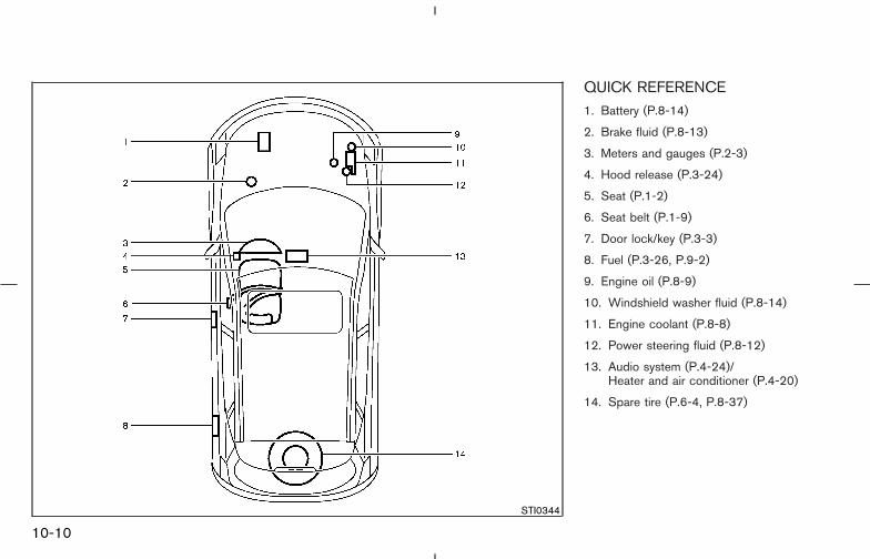
QUICK REFERENCE1. Battery (P.8-14)
2. Brake fluid (P.8-13)
3. Meters and gauges (P.2-3)
4. Hood release (P.3-24)
5. Seat (P.1-2)
6. Seat belt (P.1-9)
7. Door lock/key (P.3-3)
8. Fuel (P.3-26, P.9-2)
9. Engine oil (P.8-9)
10. Windshield washer fluid (P.8-14)
11. Engine coolant (P.8-8)
12. Power steering fluid (P.8-12)
13. Audio system (P.4-24)/Heater and air conditioner (P.4-20)
14. Spare tire (P.6-4, P.8-37)
STI0344
10-10
� 04.8.4/Z50-D/V5.0 �