Embed Size (px)
Citation preview

1
ME351A
PROJECT REPORT
THETRANSPORTER
DATE OF SUBMISSION: 26-04-14
GROUP MEMBERS:
a) Anurag Bhatt 11135 b) Ankit Shrivastava 11113 c) Ankit Yadav 11115 d) Ahsen Parvez 11416 e) Deepak Dalakoti 11235 f) Shivam Patel 11683

2
TABLE OF CONTENTS
SNo. TITLE Page No.
1 Abstract 3
2 Problem Definition 4
3 Overall Photograph of Existing real System 5
SUB-SYSTEMS
4
Pneumatics & Pulley Sub-system Schematic Analysis & Design Conclusion
6
5
Mainframe Sub-system Schematic Analysis & Design Conclusion
14
6
Carriage Sub-system Schematic Analysis & Design Conclusion
23
7 Finite Element Analysis 26
8 Design Recommendations 29
9 Design Shortcomings and Proposed changes 30
10 Appendix & Enclosures 30

3
ABSTRACT
In the present project we plan to design and analyse the transporter machine that is used for lifting heavy machinery and goods from one floor to the other. This machine acts very much like a lift but uses pneumatic piston and chain driven pulleys to perform the task. One such machine can be seen in the institute’s southern labs.
The machine primarily composes of three basic sub-systems that perform three different functions –
1. The lifting is primarily done by chain driven pulleys, which are four in number to reduce load on each pulley-chain assembly. The major force provider is a pneumatic piston cylinder arrangement operated electronically & powered by a motor connected to a pump. The cylinder is firmly attached to the main frame and lifts the load. The chain in addition to transferring force increases the range of motion without increasing the size of cylinder. Though this increases the load on the frame, it prevents the cylinders from buckling.
2. The main-frame supports the carriage and pneumatic sub-system and is fixed firmly to the ground. It comprises of prismatic guides for the carriage to slide in without swaying. It has additional safety features such as antiroll bars to prevent the whole structure from collapsing due to friction induced horizontal loads. The frame is also attached to the upper floor to provide additional support.
3. The carriage is the platform on which the machinery and goods are kept for transportation to the next floor. The base of the carriage is made of a base-plate which is further reinforced using square steel rods and bars. It is bounded by gates that can be locked to prevent any mishaps. The chain lifting the carriage is connected to the platform.

4
PROBLEM DEFINITION & SOLUTION METHODOLOGY
As a part of the project, the team divided the whole system into primarily 3 major sub-systems as mentioned in the abstract. Each sub-system was further divided into various smaller parts which were then analysed.
To begin with the analysis, the material for the whole system was taken to be 1080 HR Steel and factor of safety was taken as 3. While analysing each smaller part of the sub-systems, the critical load that the whole setup could carry corresponding to a factor of safety as 3 was calculated. After design of all such critical parts for all sub-systems, the minimum of all such critical loads obtained was taken as the critical design load for the whole system.

5
OVERALL PHOTOGRAPH OF EXISTING REAL SYSTEM

6
SUBSYSTEM 1
PNEUMATICS & PULLEY
7
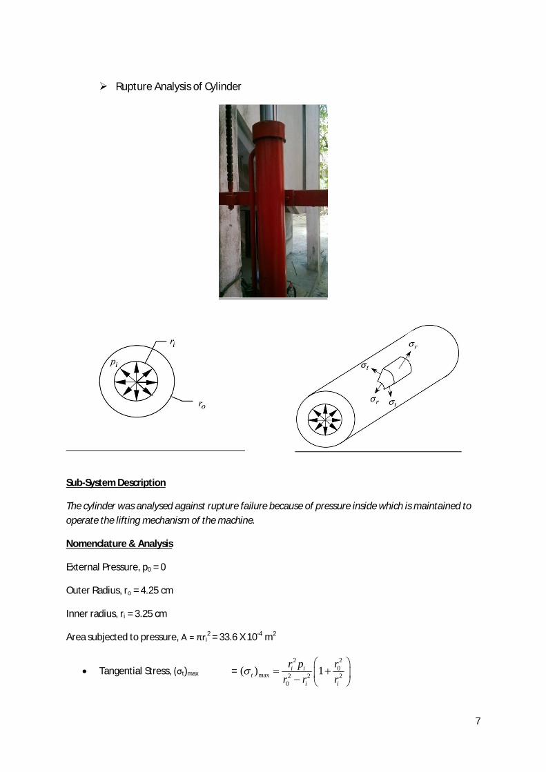
Rupture Analysis of Cylinder
Sub-System Description
The cylinder was analysed against rupture failure because of pressure inside which is maintained to operate the lifting mechanism of the machine.
Nomenclature & Analysis
External Pressure, p0 = 0
Outer Radius, ro = 4.25 cm
Inner radius, ri = 3.25 cm
Area subjected to pressure, A = πri2 = 33.6 X 10⁻⁴ m2
Tangential Stress, (σt)max = 2 2
0max 2 2 2
0
( ) 1i it
i i
r p rr r r

8
= 0.113 W X 104
Here,
W is the load weight (in Newton)
pi is the internal pressure. (All quantities in SI units)
2iWP
A
Radial Stress, (σr)max = 2 2
0max 2 2 2
0
( ) 1i ir
i i
r p rr r r
= - 0.03 W X 104
Von-Mises Stress Analysis
σ ‘ = (σA2 – σAσB + σB
2)0.5
= 0.133 W X 104
Safety factor, n = 3
Yield Strength of material, Sy = 420 MPa
0.133 W X 104 = 420 X 106 / 3
W = 10.72 tonnes This is much more than the desired load weight of 3 tonnes. Bucking of piston rod

9
Sub-System Description
The piston due to its long length was analysed for failure due to buckling while lifting the carriage.
As a worst case scenario, the buckling was checked for its topmost position when the functional length (length outside the pressurised cylinder) is the longest.
Nomenclature & Analysis
d is the diameter of the thin rod l is the functional length of piston rod
0.252
364 crP ld
CE
So, 4 3
264crd CEP
l
Substituting, Diameter of piston rod, d = 6.5 cm Buckling constant, C = 4 Modulus of Elasticity, E = 200 GPa Now, calculating Pcr Also, Pcr = 4T = 2W This gives
W = 81 tonnes This is much more than the desired load of 3 tonnes.
Design of Pulley Shaft

10
Sub-System Description
The chain lifting the carriage passes over the pulley. This pulley is mounted on a shaft which is in turn welded to the movable T section connected to the piston. The welding of the shaft is analysed for bending and shear failure.
Nomenclature & Analysis
Stress Analysis of welded joints in Bending
5 21.414 75.5 10A hr m
3 6 3200.96 10uI r m
Where
A is Weld pool area
h is leg size of the weld pool
r is the radius of the shaft
Now, calculating primary and secondary shear on weld pool
52
2 0.0281 108 101.414 ( )
2
V T TA
h
32
0.707
8 100.7072
uI h I
h
2
3
8 1022
7.03 10TL
Mc TI I
Calculating the resultant shear on weld pool
2 2 37.49 10 T
Finding the critical load bearing capacity corresponding to the resultant shear
ut min 0.4 , 0.3Sallow yS
min 0.4 420 , 0.3 770allow

11
168MPa
allownetn
65168 10 0.0749 10
37.476
T
T KN
4T W
4 7.476W KN
W = 3.05 tonnes
Checking for Pure Shear Stress
52 0.0281 10 Pa
2 0.707F T TA r h
Where
F is the net shear force on the weld joint
T is the tension in chain
utmin 0.4 , 0.3Sallow yS
min 0.4 420 , 0.3 770allow
168MPa
For n=3
allownetn
65168 10 0.0281 10
319.92
T
T KN
4T W
4 19.928.13
W KNMass tonnes
Thus, taking the minimum of the two critical loads obtained, we have

12
From Table 9.6, the chosen Electrode is of the specification E90XX
W = 3.05 tonnes, (Weld Electrode Specification ) E90XX
Yielding Test for T-section
Sub-system Description The pulley shaft is welded to a T-section which in turn is connected to the piston. This T-section is under bending loads. The following analysis checks for the yield failure of this section due to bending.
Nomenclature & Analysis
Calculating the axial bending stresses
4 42 1
2 / 2 0.05
12
a
T LMyI b b
4 4
8
0.332 0.052
10 9 1012
T
40.575 10 T
ya
Sn
Taking n=3,
40.575 10 T
64 420 100.575 10
3T
24.34T KN
This critical load as well exceeds the desired loading capacity of 3 tonnes. W = 9.9 tonnes
13
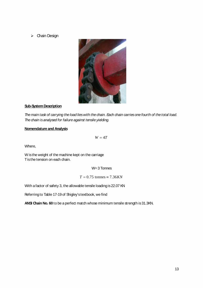
Chain Design
Sub-System Description
The main task of carrying the load lies with the chain. Each chain carries one fourth of the total load. The chain is analysed for failure against tensile yielding.
Nomenclature and Analysis
4W T
Where,
W is the weight of the machine kept on the carriage T is the tension on each chain.
W= 3 Tonnes
0.75 tonnes 7.36T KN
With a factor of safety 3, the allowable tensile loading is 22.07 KN
Referring to Table 17-19 of Shigley’s textbook, we find
ANSI Chain No. 60 to be a perfect match whose minimum tensile strength is 31.3KN.

14
SUBSYSTEM 2
MAIN-FRAME

15
Load Carrying Bar
Subsystem Description:
The chain lifting the carriage passes over the pulley. One end of the chain is fixed to the carriage frame and the other end is hinged to a bolt which in turn is strongly welded to this load carrying bar. The present analysis is a check for the strength of this weld and the weld joint connecting this bar to the mainframe.
Nomenclature and Analysis:
Weld Design for Connecting plate: Analysis for weld connecting the plate to the main frame (the left weld in the figure above)
Primary Shear in the Weld:
'1.414
V TA hd
Here,
h= leg size of weld (4mm)
d= width of weld (3cm)
T= Tension
' 5.89 kPaT

16
Secondary Shear:
"= MrJ
M= Torque due to applied tension
J= Polar area moment of inertia
2 22
2 2 2 26 1.5 2.5"= 10 15.955 kPa
0.707 [3(5 10 ) (3 10 ) ]Tx T
h
Net shear stress:
2 2 2 2' " 2 ' "cos (5.89) (15.955) 2(5.89)(15.955)cos 19.64 kPanet T T
Using factor of safety of n=3, checking for failure:
allownetn
63168 10 19.64 10
3T
2.851 T kN 4 11.404W T kN
1.1 9.8WM tonnes
W = 1.1 tonnes
This load is much less than the desired loading capacity of 3 tonnes.
Hence, we need to iterate and look for alternatives like
Change the leg size, weld length Change the material of base metal Change the weld pattern Compromising with factor of safety

17
Checking for changed leg size and length of weld
Now,
h=5mm
d=5cm
Proceeding similarly as above
' 2.82 kPaT
" 7.8 kPaT
2 2' " 2 ' "cos 45 9.9 kNnet T
W = 2.4 tonnes We are still short of the desired capacity of 3 tonnes.
On changing the Base Material:
New Material: 440 Q&T steel
1770S 1640
ut
y
S MPaMPa
allow 0.3 , 0.4
= 531 , 656ut yS S
63531 10 9.9 10
3T
W = 7.32 tonnes However changing to this base material is not economically feasible. Hence, we will seek an alternative method to increase the load bearing capacity.
Changing the weld pattern:
Considering a 4-sided square weld pattern
Primary Shear:
'0.707 (2b 2d)
V TA h

18
3.53 kPa
1.414 0.004 0.05T T
Area moment of inertia:
3
J6u
b d
365 5
106
6 30.707 0.471 10J J m
Secondary Shear:
" MrJ
2 2
6
6.5 10 (5 10 / 2) 4.87 kPa0.471 10
T T
Net Torque:
2 2' " 2 ' "cos45 7.01 kNnet T
6 316810 7.01 10 kPa3
allownet T
n
7.987 T kN 4 31.948W T kN
3.26 9.8WM tonnes
W = 3.26 tonnes
As observed, the weld pattern change makes the allowable load of 3.26 tonnes. Hence, it meets our desired requirement and seems most feasible of all the alternatives discussed above.
Changing the factor of safety:
2 : W=4.8 tonnes3: W=2.4 tonnes
nn
Compromising on the factor of safety should be a measure of last resort.

19
Weld design of clamped & welded end of the chain:
The weld is assumed to be under shear stress only.
Checking for shear stress acting on the weld
1.414shearT
hd
2 2 3.5 kN1.414(4 10 )(5 10 )
T T
Allowable Stress on the weld:
0.6Sy all
6
6
0.6(420) 10252 10
all
all Pa
6
3 3252 103.5 10 3.5 103 3all T T
4WT
W = 9.8 tonnes
So, the weld can bear up to 9.8 tonnes which is acceptable as per our design requirements.
Analysis of failure for anti-roll bar

20
Subsystem Description
Anti-roll bars have been incorporated to restrict horizontal deflection of the main frame prismatic bars. The primary cause behind this possibility of deflection is the net force in the horizontal direction due to the frictional forces acting between the pulley and chain. This section analyses possible failures of anti-roll bars.
Nomenclature and Analysis
In the figure,
FH = Force carried by anti-roll bar when carriage is at the highest position
FL = Force carried by anti-roll bar when carriage is at the lowest position
FX = Frictional Force

21
Finding Friction force
An angle θ, the tension is given by
1T Te
Where T is the tension at one end of the pulley
On an infinitesimal increment d , the tension force is
( d )2 (1 )T Te Te d
From force balance on the infinitesimal element d ,
1 2 1 2( )sin( / 2) ( )sin( / 2)N T T d T T d
Since Fd = µN
Where Fd is friction force and N is normal force, we have
1 20 0 0
F ( )sin / 2 ( (1 ))sin / 2 (2 ))sin / 2d T T d T e e d d Te d d
0 0
F sin sind Te d T e d
0.2
sing 0.20.961538 (1 e ) 0.555T 0.555(W/ 4)d
UF
22
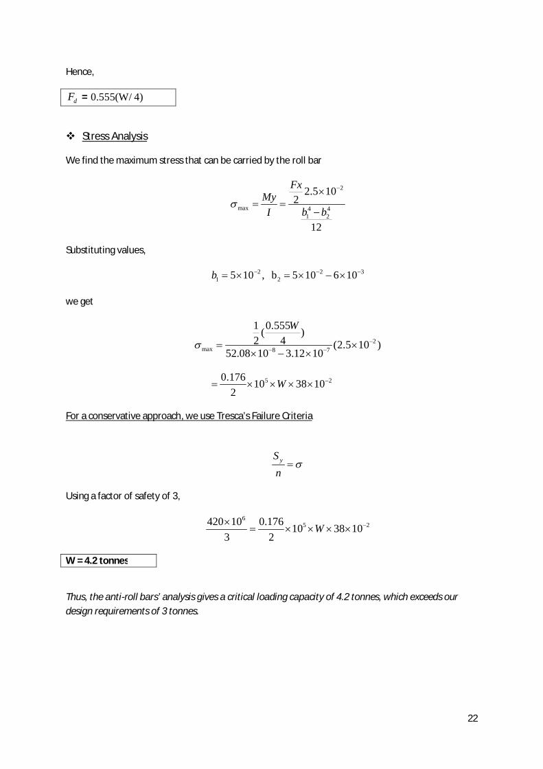
Hence,
dF = 0.555(W/ 4)
Stress Analysis
We find the maximum stress that can be carried by the roll bar
2
max 4 41 2
2.5 102
12
FxMy
b bI
Substituting values,
2 2 31 25 10 , b 5 10 6 10b
we get
2max 8 7
1 0.555( )2 4 (2.5 10 )
52.08 10 3.12 10
W
5 20.176 10 38 102
W
For a conservative approach, we use Tresca’s Failure Criteria
ySn
Using a factor of safety of 3,
65 2420 10 0.176 10 38 10
3 2W
W = 4.2 tonnes
Thus, the anti-roll bars’ analysis gives a critical loading capacity of 4.2 tonnes, which exceeds our design requirements of 3 tonnes.
23
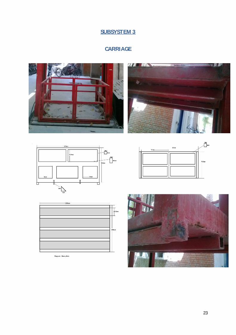
SUBSYSTEM 3
CARRIAGE

24
Sub-system Description
The base of the carriage has 3 basic components –a base plate, 2 reinforcing side bars and 3 square supporting bars. The present analysis checks for the failure of welds of reinforcement bars to the frame of the carriage.
Due to the very complicated way of welding pattern which is not only in different planes but of different nature-fillet and butt and moreover sharing a combination of shear loading and bending loads, we have assumed all the 4 welds of the reinforcing bar to be fillet welds and sharing shear loads only.
Furthermore, since the base plate lifts the load W, it is still highly ambiguous as to what proportion of load is shared by the reinforcement bars and supporting bars separately.
Nomenclature & Analysis
Weight sharing by reinforcement & bending bars:
4 42 1
/12 0.05
12
a
FLMyI b b
max1yI
1 22 3W W W
4 41 2
1 2384 384W l W l
EI EI
1 1
2 2
W IW I
3
1
3.5 1.512
I
4 4
25 4.4
12I
31
4 42
3.5 1.5
5 4.4WW
41
2
7.5 10WW

25
2 1334W W
2 4006WW
120024006
WW
Bending Analysis of square supporting bars:
4 42 1
/12 0.054006
12
a
WLMyI b b
4 4
1.5 /12 0.054006
0.1 0.0912
W
0.54W
ya
Sn
6420 100.543
W
W =26.42 K tonnes Hence, the critical loading capacity that is observed from bending analysis is way ahead of the desired load carrying capacity of 3 tonnes.
Shear Failure analysis of Reinforcement bar welds:
2 1 area, A =0.707(h 150 3.5 6 )tTotal h
1 2h 2 , h 4mm mm
5 2227.65 10tA m
6168 10 18 tonnes2 3t
W WA
no intermittent welding between plate and bar:If
Only 6 butt welds, then A (3.5 6)(0.707 4)t
26
6168 10 2 3t
WA
W = 6.7 tonnes Hence, the critical load carrying capacity from the analysis of reinforcement bar welds is more than the desired load carrying capacity of 3 tonnes.
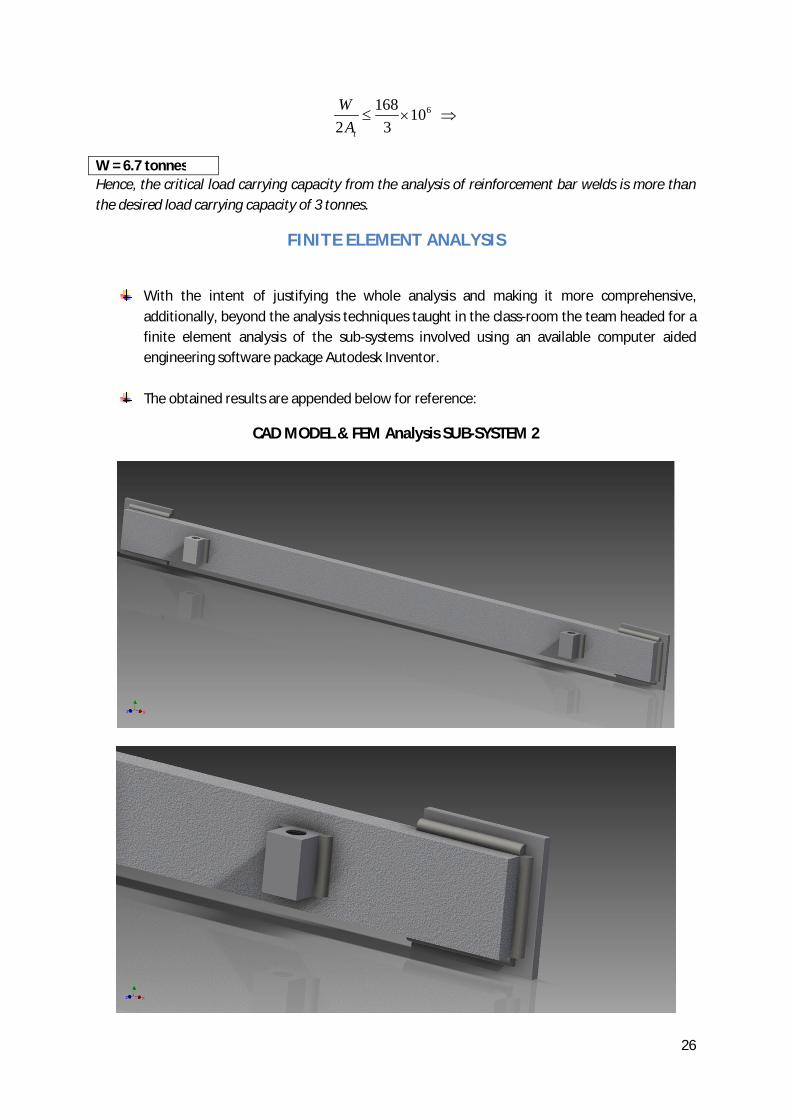
FINITE ELEMENT ANALYSIS
With the intent of justifying the whole analysis and making it more comprehensive, additionally, beyond the analysis techniques taught in the class-room the team headed for a finite element analysis of the sub-systems involved using an available computer aided engineering software package Autodesk Inventor.
The obtained results are appended below for reference:
CAD MODEL & FEM Analysis SUB-SYSTEM 2

27
CAD MODEL & FEM ANALYSIS SUBSYSTEM 3

28
Fig(a). Check for factor of safety of reinforcement side bars against bending
Fig(b). Checking deflections of reinforcement side bars
Fig(c). Checking factor of safety for the 3 welds on reinforcement side bars’ ends

29
DESIGN RECOMMENDATIONS
The design process was aimed at the construction of a lifting machine of load carrying capacity of 3 tonnes
After the holistic design of all the three subsystems the following can be concluded : Results of Analysis of SUB-SYSTEM 1:
o Rupture Analysis of cylinder Critical Load carrying capacity = 10.72 ton
o Buckling of piston rod Critical Load carrying capacity = 81 ton
o Yielding of T-section Critical Load carrying capacity = 9.9 ton
o Failure of pulley shaft weld Critical Load carrying capacity = 3.05 ton
Hence, the pulley shaft weld is the most critical element after the analysis of sub-system 1 which dictates the load carrying capacity of the machine and also exceeds our load carrying requirement of 3 tonnes.
The appropriate chain for the desired loading capacity is designed to be ASTM 60. Overall, no specific design changes are proposed.
Results of Analysis of SUB-SYSTEM 2:
o Load Carrying Bar Analysis Weld Design of Connecting Plate
Critical Load carrying capacity = 1.1 ton Weld design of clamped & welded end of the chain
Critical Load Carrying capacity = 9.8 ton o Anti-Roll Bars Design
Critical Load carrying capacity = 4.4 ton As observed after analysis, the present design for main-frame became non-
functional for design loads greater than 1.1 tonnes. As a consequence, we propose the following design alternatives:
Changing the leg size and weld length (Critical Load = 2.4 ton) Changing the material of base metal (Critical Load =7.32 ton) Changing the weld pattern (Critical Load = 3.26 ton) Compromising with factor of safety(Critical Load =2.4 ton-safety factor 3 and
4.8 ton-safety factor 2) After serious deliberations & brainstorming sessions, we propose a change in the
weld pattern on the connecting plate of the load carrying bar as the most feasible solution for sub-system 2 to allow a load lift of 3 tonnes.
Results of Analysis of SUB-SYSTEM 3: o Bending Analysis of square supporting bars
Critical Load carrying capacity = 26.40 kilo ton
o Shear Failure analysis of Reinforcement bar welds Critical Load carrying capacity = 6.7 ton Hence, there is no specific design change needed for the sub-system 3.

30
DESIGN SHORTCOMINGS & PROPOSED CHANGES
In-spite of the team’s efforts to incorporate all the minute details of the present working model present at the service location for design, yet the design has some shortcomings which are discussed below :
The exact length of the piston rod is not known, so it was assumed that the length is just
sufficient to raise the T-section to the desired height. In case this is not the case, the buckling analysis needs to be revised accordingly.
Secondly, there is a novel use of chain along with a pulley in the model present. The
references to the analysis of such systems could not be found in the literature. So, the team modelled the pulley-chain system similar to a cable-pulley system and found the frictional forces thus generated and designed the anti-roll bars accordingly. This might need a detailed review especially in the context for the design of anti-roll bars and the desired pulley service life.
In the carriage system, the welds at the ends of reinforcement bars are a complex
combination of fillet and butt welds whose design is non-conventional analytically because of the altogether different behaviour of both the welds. So, the designers assumed all welds as fillet weld and performed the analysis. This might not need detailed and explicit attention although these welds are crucial since as observed in literature fillet welds are comparatively weaker than butt welds. Thus our design is more conservative.
As seen through the analysis, the load carrying bar is the weakest and most critical element of the whole assembly. The deciding portion of the load carrying bar comes out to be the weld at the connecting plate whose design was modified by the team for loading capacity enhancement. It is proposed (without proof) that instead of changing the weld pattern, much reliable and larger increase in capacity could be obtained in case reinforcement of the bar using members as in a truss could be done. Although this needs to be verified and the analysis needs to be included in the report.
APPENDIX & ENCLOSURES